 Trusted Since 2001





Quick Answer
Security Parts stocks 21 replacement parts for the LCN 9150 Benchmark electromechanical swing door operator. The key components are the 9150-3454S motor gearbox assembly with switch, the 9150-3462SC standard control box, the 9150-77 main arm, the 9150-3077 regular arm and 9150-3077L long arm, the 9150-79 rod and shoe, the 9150-72MC metal cover, the 9150-3018 mounting bracket, the 9150-360 24v SO kit, three switch bracket sizes, three screw pack variants, and cover components. All 21 parts are confirmed in stock.
What Is the LCN 9150?
The LCN 9150 is a low-energy electromechanical swing door operator in the LCN Benchmark series. It is designed for top-jamb push-side mounting on paired interior commercial doors and is widely installed in healthcare facilities, government buildings, universities, and commercial offices where ADA-compliant automatic access is required.
The 9150 operates by using a motor gearbox to physically swing the door open on activation, hold it open for an adjustable period, then close it. It includes Push N Go activation, which allows non-switch activation when a pedestrian manually pushes the door to approximately 5 degrees. The operator detects the movement and takes over, carrying the door to the full open position automatically. Power Boost provides additional closing force near the latch to overcome wind load and seal resistance.
The 9150 meets ANSI/BHMA A156.19, ANSI A117.1, UL 325, and ADA requirements, and is UL listed for fire-rated applications.
How Does the LCN 9150 Differ from the 9130 and 9140?
All three models belong to the Benchmark series and share the same part families. The mounting configuration is what separates them:
| Model | Mounting Side | Door Configuration |
|---|---|---|
| 9130 | Pull side | Single door |
| 9140 | Push side | Single door |
| 9150 | Push side, top jamb | Paired doors (independent or simultaneous pair) |
The 9150 ships with two motor gearboxes and two control boxes, one for each door leaf. If you have a pair of doors with an operator across the full header, you have a 9150 installation. For the full Benchmark series parts catalog, see the LCN 9130/9140/9150 Benchmark series page.
What Parts Does the LCN 9150 Come With from the Factory?
The LCN 9150 ships from the factory with the following components included as standard:
- Motor gearboxes (two, one per door leaf)
- Control boxes (two, one per door leaf)
- Mounting plate (operator mounting bracket)
- Regular arms (two, one per leaf)
- 72-inch metal cover (non-handed, extruded aluminum)
- Wood and machine screw packs
Actuators, wall switches, motion sensors, and other activation devices are not included in the standard shipment and must be ordered separately.
LCN 9150 Parts by Component Category
Motor Gearbox Assembly
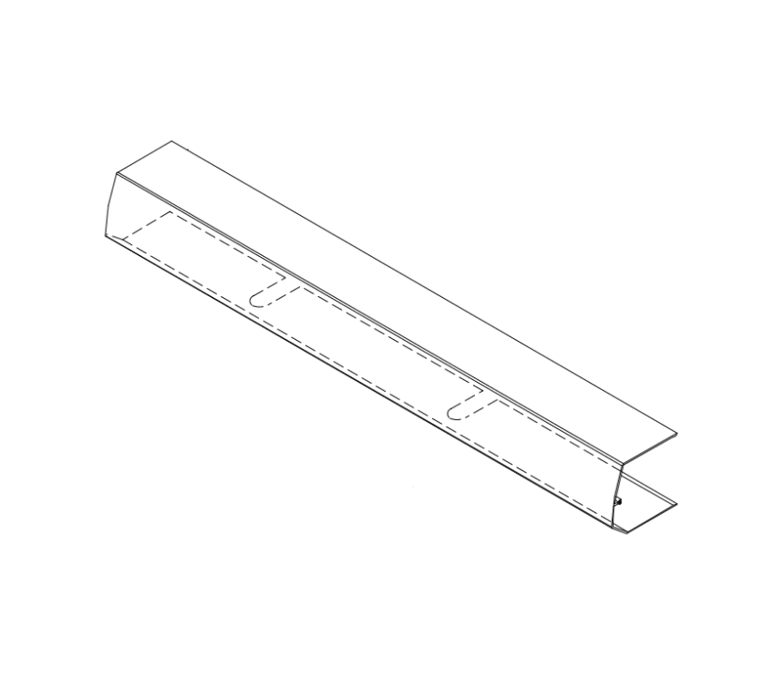
LCN 9150-3454S Motor Gearbox Assembly with Switch. The primary drive unit for the LCN 9150 operator. View product page.
| Part Number | Description | Function |
|---|---|---|
| 9150-3454S | Motor Gearbox Assembly with Switch | The drive unit that physically opens the door. Converts electrical power into arm rotation through a gear reduction system. Switch included for on/off control. |
How Do I Know If the Motor Gearbox Has Failed?
The motor gearbox is the most costly replacement component on the 9150. Before ordering, confirm the failure is in the motor gearbox and not the control box or wiring. The control box has two LED indicator lights: one showing power to the control box itself and one showing power to the motor gearbox. If the motor gearbox LED is off while the control box LED is on, the fault is in the motor gearbox or the cable connection between the two units. If both LEDs are off, the fault is upstream in the power supply or wiring.
Motor gearbox failure symptoms include the door not moving at all when an activation signal is received, the arm moving weakly without enough force to open the door against normal resistance, or the door opening but not completing the full travel arc.
Control Box
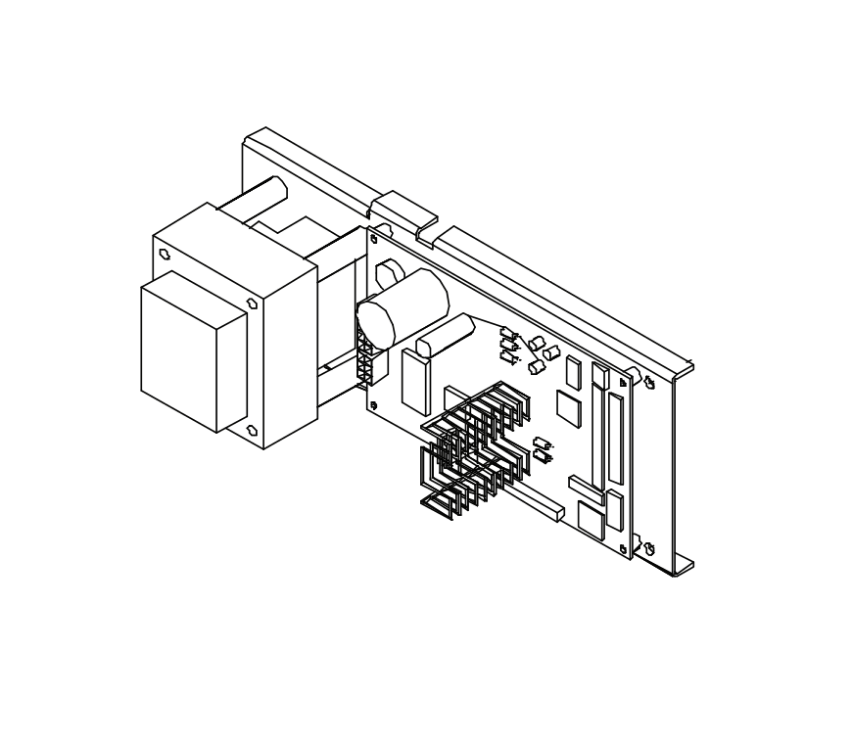
LCN 9150-3462SC Standard Control Box. The microprocessor controller that manages all operator functions including Push N Go, opening time, hold-open delay, and Power Boost. View product page.
| Part Number | Description | Function |
|---|---|---|
| 9150-3462SC | Standard Control Box | Microprocessor controller managing opening speed, closing speed, hold-open time delay (adjustable up to approximately 30 seconds), Power Boost, and Push N Go. All potentiometers are clearly labeled. LED lights indicate power status to control box and motor gearbox. |
What Does Push N Go Do and Why Does It Matter for Parts?
Push N Go is the feature that allows the 9150 to operate without a wall switch or sensor activation. When someone manually pushes the door open to approximately 5 degrees, the control box detects the movement through the motor gearbox's built-in sensor and takes over, carrying the door to the full open position. After the hold-open delay expires, the control box signals the motor gearbox to close the door.
When Push N Go stops working -- the door opens manually but the operator does not take over -- the fault is almost always in the control box or the connection between the control box and motor gearbox, not in the motor gearbox itself. Replacing the control box (9150-3462SC) is the correct diagnostic step before replacing the motor gearbox (9150-3454S).
How Do I Identify a Failed Control Box Versus a Failed Motor Gearbox?
- Control box fault: Door does not respond to activation signals. Push N Go not working. Door opens but does not hold for the set delay. Opening or closing speed cannot be adjusted. Both LEDs off when power is confirmed at the wall outlet.
- Motor gearbox fault: Control box LED is on but motor gearbox LED is off. Door does not move despite a valid activation signal. Arm moves but without enough force to open the door. Unusual noise from the operator housing during activation.
Mounting Bracket
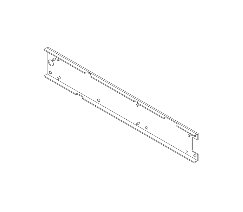
LCN 9150-3018 Mounting Bracket. The standard bracket that mounts the motor gearbox to the header frame. View product page.
| Part Number | Description |
|---|---|
| 9150-3018 | Mounting Bracket. Standard bracket that attaches the motor gearbox assembly to the header frame or door frame. Requires a minimum head frame of 2 inches (51mm) and minimum top rail of 2 inches (51mm). Flush ceiling installation requires a minimum of 5-1/4 inches clearance. |
Arms
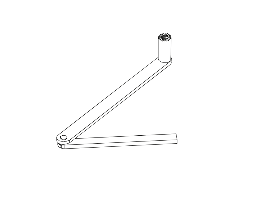
LCN 9150-77 Main Arm. The primary connection arm between the operator spindle and the door. View product page.
| Part Number | Description | Use When |
|---|---|---|
| 9150-77 | Main Arm | Primary arm connecting operator spindle to door. Non-handed. Use for standard push-side mounting configurations. |
| 9150-3077 | Regular Arm | Non-handed regular arm. Push installations where reveal does not exceed 6 inches (152mm). Ships as standard with the 9150. |
| 9150-3077L | Long Arm | Non-handed long arm. Push installations where reveal is between 6 inches and 9-3/4 inches (248mm). Required when standard arm does not have enough reach for the door geometry. |
How Do I Choose Between the Regular Arm and the Long Arm?
Measure the reveal of the installation. The reveal is the distance from the face of the door to the face of the frame on the push side. If the reveal is 6 inches or less, the 9150-3077 regular arm is correct. If the reveal is between 6 inches and 9-3/4 inches, the 9150-3077L long arm is required. Using the regular arm on a reveal that requires a long arm will result in incorrect arm geometry and poor door control. The operator will not be able to swing the door to the full open angle.
Rod and Shoe
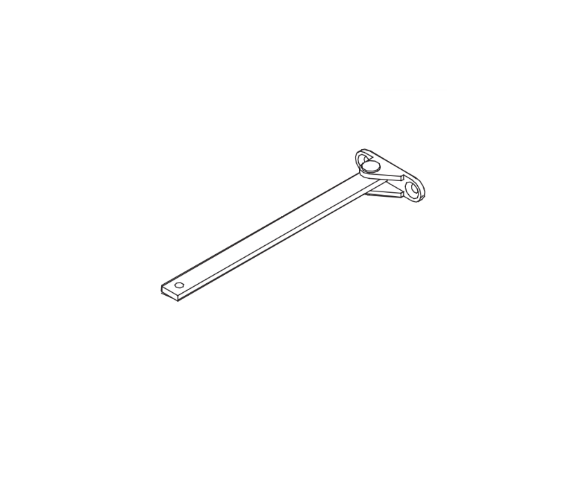
LCN 9150-79 Rod and Shoe. Connects the arm to the door surface on push-side installations. View product page.
| Part Number | Description | Paired With |
|---|---|---|
| 9150-79 | Rod and Shoe | Paired with 9150-3077 regular arm. For standard-reveal push installations. |
| 9150-79LR | Long Rod and Shoe | Paired with 9150-3077L long arm. For deep-reveal push installations where a longer rod is required. |
Cover and Trim Components
| Part Number | Description | Notes |
|---|---|---|
| 9150-72MC | Metal Cover, 72 inch | Non-handed extruded aluminum cover enclosing the operator assembly. Standard length is 72 inches. Ships as standard with the 9150 operator. |
| 9150-163 | Cover Insert | Insert that covers the operator shaft opening in the cover. Prevents debris entry and completes the finished appearance. |
| 9150-163-1 | Cover Endcap Inserts | Inserts that fit inside the cover endcaps at each end of the cover. Complete the sealed appearance at the cover ends. |
| 9150-334 | Cover Endcaps | Black plastic endcaps that close each end of the cover assembly. Replace when cracked, missing, or damaged. |
AC Power Cable
| Part Number | Description |
|---|---|
| 9150-3498-2A | AC Power Cable, 29 inch. Connects the control box to the motor gearbox. Replace when the cable is damaged, shows visible insulation wear, or when the motor gearbox LED is off and the cable and connectors have been confirmed as the fault point. |
Secondary Output (SO) Kit
| Part Number | Description |
|---|---|
| 9150-360 | 24v SO Kit. Enables the secondary output circuit on the 9150 operator. The secondary output activates when the operator receives an open command, allowing it to trigger an accessory device such as a door hold-open relay, an electric strike, or an access control output. This is an optional accessory not included in the standard operator shipment. Order this when adding secondary output functionality to an existing 9150 installation. |
Switch Brackets
| Part Number | Description | Length |
|---|---|---|
| 9150-3351-1 | Switch Bracket | 29 inch |
| 9150-3351-2 | Switch Bracket | 41 inch |
| 9150-3351-3 | Switch Bracket | 51 inch |
The switch bracket positions the on/off switch at the end of the operator cover. The correct size depends on the door width and the length of the cover assembly. Measure the installed cover length to determine which bracket size applies.
Screw Packs
| Part Number | Description | Use For |
|---|---|---|
| 9150-MS-PUSH | Screw Pack, Push Arm | Push-side arm mounting configurations |
| 9150-MS-PULL | Screw Pack, Pull Arm | Pull-side arm mounting configurations |
| 9150-MS-HDR | Screw Pack, Header | Header mounting |
Documentation and Packaging
| Part Number | Description |
|---|---|
| 9150-Rebox Kit | Rebox Kit including box and instruction sheet. Used when repackaging or documenting a field unit. |
Troubleshooting Common LCN 9150 Problems
Why Is the LCN 9150 Not Opening the Door?
Check in this order before ordering parts:
- Confirm the on/off switch on the operator cover is set to On. This is the most common service call for an operator that appears dead.
- Confirm power is reaching the control box. Check the LED on the control box. If it is off, the fault is in the power supply, circuit breaker, or wiring to the unit, not in the operator itself.
- If the control box LED is on but the motor gearbox LED is off, check the AC power cable (9150-3498-2A) connection between the two units. If the cable is secure and the motor gearbox LED is still off, the motor gearbox (9150-3454S) needs replacement.
- If both LEDs are on and the door still does not open on activation, try a manual Push N Go activation. If Push N Go works but switch activation does not, the fault is in the activation device (wall switch, sensor, or actuator), not in the operator components.
Why Is the LCN 9150 Not Holding the Door Open?
The hold-open delay is set by the potentiometer on the control box (9150-3462SC). If the door is not holding open for the expected duration, the potentiometer setting may have drifted or the control box may have lost its settings. Adjust the hold-open time potentiometer on the control box. If adjustments have no effect, the control box needs replacement.
Why Is the LCN 9150 Door Closing Too Hard or Too Fast?
Opening speed and closing speed are both adjustable via potentiometers on the control box. If the door is closing too fast or with too much force, the closing speed setting may have been changed or the Power Boost setting may be too high. Adjust the closing speed and Power Boost potentiometers on the 9150-3462SC control box. If the behavior cannot be corrected through adjustment, the control box needs replacement.
Why Is the Arm Not Reaching the Door on the Push Side?
If the arm is not reaching the door or the geometry appears incorrect, the arm may be the wrong type for the reveal depth. Measure the reveal from the door face to the frame face on the push side. A reveal over 6 inches requires the 9150-3077L long arm and the 9150-79LR long rod and shoe. Using the standard 9150-3077 arm on a deep-reveal installation is the most common arm-related service error.
LCN 9150 Installation Requirements That Affect Part Selection
Before ordering any replacement arm, rod, bracket, or cover for the LCN 9150, confirm the installation dimensions. The 9150 is a paired-door operator and its parts selection depends on several measurable site conditions.
What Are the Head Frame and Top Rail Requirements for the LCN 9150?
The LCN 9150 requires a minimum head frame depth of 2 inches (51mm) and a minimum top rail depth of 2 inches (51mm). These minimums are required for the mounting bracket (9150-3018) to seat properly. If the head frame is narrower than 2 inches, the standard mounting configuration is not possible and an alternate bracket solution is needed. For flush ceiling installations, 5-1/4 inches of clearance above the door is required.
What Are the Reveal Limits for the LCN 9150 Push Arm?
Push installations must not exceed 6 inches (152mm) of reveal when using the regular arm (9150-3077). For reveals between 6 inches and 9-3/4 inches (248mm), the long arm (9150-3077L) with the long rod and shoe (9150-79LR) is required. These are not guidelines -- exceeding the reveal limit with the wrong arm results in mechanical binding, incorrect door travel, and potential damage to the operator spindle.
What Compliance Standards Does the LCN 9150 Meet?
The LCN 9150 meets the following standards, which are important for facilities managers ordering replacement parts on code-compliant openings:
- ANSI/BHMA A156.19 -- Low-energy power-operated doors
- ANSI A117.1 -- Accessibility requirements
- Americans with Disabilities Act (ADA) compliant
- UL 325 listed
- UL listed for fire-rated applications
When replacing components on a fire-rated opening, confirm that all replacement parts are the same specification as the originals. Do not substitute non-OEM components on fire-rated applications without confirming compliance with the authority having jurisdiction.
How to Identify Your LCN 9150 Before Ordering Parts
The date of manufacture label on the LCN 9150 is on the operator body, typically inside the cover near the control box. It shows the model number (9150 for a paired-door push-side installation), the manufacturing date, and the serial number. Confirm the model number before ordering any replacement component.
If the label is unreadable, identify the operator by the configuration:
- A paired header with an operator on both door leaves, mounted on the push side, is a 9150 installation.
- A single-door installation on the pull side is a 9130.
- A single-door installation on the push side is a 9140.
Parts from the 9130 and 9140 share many part numbers with the 9150 because all three are Benchmark series operators. The motor gearbox, control box, arms, rods, and cover components are common across the three series. Always verify the part number prefix matches your specific model before ordering.
For a broader overview of LCN door operator component categories and what failure looks like in each one, see the door operators parts guide.
What Does Each Potentiometer Do on the LCN 9150 Control Box?
The LCN 9150-3462SC control box has five labeled potentiometers. Each one controls a separate phase of the door cycle. When the door is behaving incorrectly, knowing which potentiometer to adjust avoids unnecessary part replacement.
| Potentiometer | What It Controls | Adjust When |
|---|---|---|
| Opening Speed | Speed at which the motor drives the door from closed to backcheck position | Door opens too fast (impact risk) or too slowly for the intended traffic flow |
| Backcheck Speed | Speed at which the door decelerates from the backcheck position to the full open position | Door slams against the stop at full open, or decelerates too early |
| Hold Open Time Delay | How many seconds the door holds at the full open position before beginning to close. Adjustable up to approximately 30 seconds. | Door closes before occupants can pass, or holds open too long |
| Closing Speed | Speed at which the spring closes the door from full open to latch position | Door closes too fast (slamming) or too slowly (fails to latch consistently) |
| Latch Position | The point at which additional closing assistance is applied near the latch to overcome seal resistance. This is the Power Boost zone. | Door consistently fails to latch in the final inch of travel |
All five potentiometers are clearly labeled on the 9150-3462SC control box. Adjustment is made with a small flathead screwdriver through the access point on the control box face. Always make small adjustments and test the door cycle before adjusting further. If potentiometer adjustment has no effect on the symptom, the control box needs replacement.
What Does Each LED Mean on the LCN 9150 Control Box?
The 9150-3462SC control box has two LED indicator lights. Understanding exactly what each LED indicates prevents misdiagnosis before ordering replacement parts.
| LED | When It Is On | When It Is Off |
|---|---|---|
| Power LED | Power is applied to the control board. Stays on as long as power is connected, including during hold-open and closing. | Power is not reaching the control board. Fault is in power supply, circuit breaker, or wiring upstream of the control box. |
| Motor LED | Motor drive circuit is energized. This only happens during the opening stroke of the door cycle. | Motor is not running. This is NORMAL during hold-open and closing -- the motor LED being off during closing does not indicate a fault. |
Key diagnostic rule: If the Power LED is on but the Motor LED stays off when an open signal is sent and the door does not move, the fault is in the motor gearbox (9150-3454S) or the AC power cable (9150-3498-2A) connecting it to the control box. If the Power LED is also off, the fault is upstream of the control box in the power supply or circuit.
How Do I Run a Sizing Cycle After Replacing the LCN 9150 Motor Gearbox?
After replacing the motor gearbox (9150-3454S), a sizing cycle must be completed before the operator returns to normal automatic service. The sizing cycle allows the control box to learn the full travel of the door and set the open counter correctly.
During the sizing cycle, the door drives automatically to the full open position. The speed during sizing is controlled automatically by the control box and cannot be adjusted from the potentiometers. Once the door reaches the full open position, the system sets the open counter and the operator is ready for normal use.
If the sizing cycle is skipped after a motor gearbox replacement, the operator will not function correctly and may reverse or stop short of the full open position. The sizing cycle is also required any time the mounting bracket position is changed or the door travel geometry is altered.
What Happens to the LCN 9150 During a Power Failure?
The LCN 9150 Benchmark is designed to function as a manual door closer during a power failure. When power is lost, the motor drive circuit deactivates and the door falls back to spring-powered operation at Size 3 spring force. This allows the door to continue closing under spring power even without electricity, which is critical for fire-rated openings where the door must close and latch on a power interruption.
This behavior means a fire-rated 9150 installation will still protect the opening during a power outage. It also means that during a power outage, if the door is not closing correctly, the fault may be in the spring mechanism rather than the motor or control box. Inspect the spring and arm geometry before ordering electronic components when the symptom occurs during a power outage.
What Is the Minimum Door Width for the LCN 9150?
Confirm the door width before ordering parts to ensure the 9150 is the correct model for the installation.
| Configuration | Minimum Door Width |
|---|---|
| 27-inch push operator (standard 9150) | 26 inches minimum per leaf |
| 27-inch pull operator | 30 inches minimum per leaf |
| Head frame minimum | 2 inches (51mm) |
| Top rail minimum | 2 inches (51mm) |
| Flush ceiling clearance | 5-1/4 inches above door |
Does the LCN 9150 Require a Certified Technician to Service?
LCN states that technicians must be AAADM (American Association of Automatic Door Manufacturers) certified to work on or service automatic door operators. AAADM certification is a training and safety standard for professionals who install and service power-operated pedestrian doors.
Facilities managers and building engineers can identify failing components, read the LED indicators, and make basic potentiometer adjustments. However, full disassembly, motor gearbox replacement, and sizing cycle completion should be performed by an AAADM-certified technician to ensure proper operation on fire-rated and ADA-compliant openings. Call 845-935-0301 to discuss part identification before placing an order.
Complete LCN 9150 Parts Reference Table
| Part Number | Description | Category |
|---|---|---|
| 9150-3454S | Motor Gearbox Assembly with Switch | Motor |
| 9150-3462SC | Standard Control Box | Controller |
| 9150-3018 | Mounting Bracket | Mounting |
| 9150-77 | Main Arm | Arm |
| 9150-3077 | Regular Arm (non-handed) | Arm |
| 9150-3077L | Long Arm (non-handed) | Arm |
| 9150-79 | Rod and Shoe (regular arm) | Arm / Rod |
| 9150-79LR | Long Rod and Shoe (long arm) | Arm / Rod |
| 9150-72MC | Metal Cover, 72 inch | Cover |
| 9150-163 | Cover Insert | Cover |
| 9150-163-1 | Cover Endcap Inserts | Cover |
| 9150-334 | Cover Endcaps | Cover |
| 9150-3498-2A | AC Power Cable, 29 inch | Electrical |
| 9150-360 | 24v SO Kit | Accessory |
| 9150-3351-1 | Switch Bracket, 29 inch | Switch Bracket |
| 9150-3351-2 | Switch Bracket, 41 inch | Switch Bracket |
| 9150-3351-3 | Switch Bracket, 51 inch | Switch Bracket |
| 9150-MS-PUSH | Screw Pack, Push Arm | Screw Pack |
| 9150-MS-PULL | Screw Pack, Pull Arm | Screw Pack |
| 9150-MS-HDR | Screw Pack, Header | Screw Pack |
| 9150-Rebox Kit | Rebox Kit, Box and Instruction Sheet | Documentation |
Where to Order LCN 9150 Parts
Security Parts stocks all 21 LCN 9150 replacement components. Parts ship same day when ordered before the daily cut-off. Call 845-935-0301 for pre-order compatibility support or to confirm a part number before placing an order.
For the broader LCN door operator parts catalog organized by operator series, see the door operators parts guide. For LCN power-assist sliding door operator parts, see the LCN 9530IQ parts guide. For the full Benchmark series parts catalog covering the 9130, 9140, and 9150, see the LCN 9130/9140/9150 Benchmark series page. For all door operator parts and accessories, see the door operators category.
About This Guide
Written by the Security Parts team. Security Parts has supplied commercial door hardware components to facilities managers, building engineers, contractors, and service technicians since 2001. All 21 LCN 9150 parts listed in this guide are verified in stock with same-day shipping on stocked components. Call 845-935-0301 for pre-order identification or compatibility support. For related operator parts guides, see the door operators parts guide and the LCN 9530IQ parts guide.