RSS

Blog posts of '2026' 'September'

Exit Device vs Panic Bar: What Is the Difference and Which One Do You Need

Quick Answer

In everyday commercial door hardware practice, "exit device," "panic bar," and "panic hardware" are commonly used to refer to the same category of hardware. These are door-mounted assemblies with a horizontal push element that releases a latch when pressed, allowing fast single-motion egress. The terms originate from different codes and professional contexts, which is why buyers encounter all three in specifications, purchase orders, and field conversations.

That said, terminology matters in two specific situations: when comparing standard panic hardware to fire exit hardware on a fire-rated door assembly, and when reading code requirements that use one term but not another. This guide explains how the terms are used in practice, where the important distinctions lie, and how to confirm which device type applies to your opening.


Where the Terms Come From

The three terms most buyers encounter are "panic hardware," "exit device," and "panic bar." Each comes from a different context.

"Panic hardware" is the term used in NFPA 101, the Life Safety Code. NFPA 101 defines panic hardware as a latching device that allows the door to open from the egress side by applying force to a bar or panel extending at least half the door width, not requiring the use of a key, special knowledge, or effort to operate.

"Exit device" is the term used in the International Building Code (IBC). The IBC references exit devices in its egress requirements, describing devices that allow doors to be opened from the egress side without a key, special tool, or prior knowledge.

"Panic bar" is an informal industry shorthand that refers to the horizontal push bar or crossbar that is the most visible component of the device. In field use, "panic bar" is widely used to refer to the complete exit device assembly, not just the bar component. You will encounter all three terms used interchangeably in specifications, purchase orders, and product catalogs.

For most commercial door hardware decisions, the key understanding is this: whether the project documents say "panic hardware" or "exit device," they are generally describing the same product category. The applicable code for your jurisdiction and the fire rating status of the door determine the specific device requirements.


What Is an Exit Device
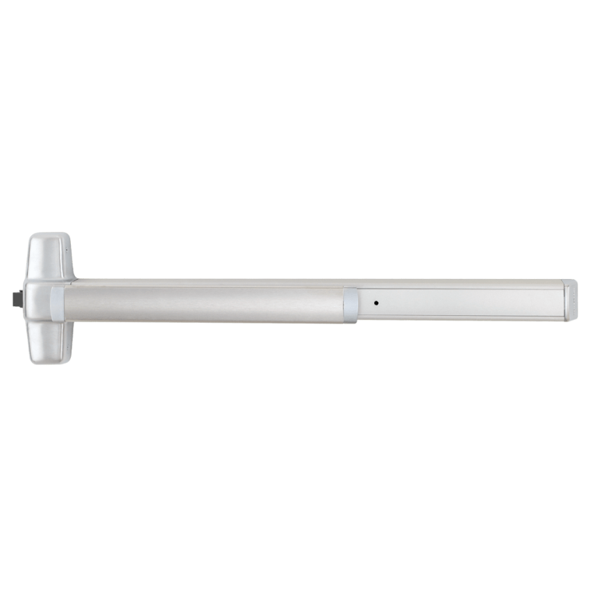
Von Duprin 98/99EO Rim Exit Device -- standard panic hardware for commercial egress doors, exit-only configuration

Von Duprin 98/99EO Rim Exit Device, Exit Only. A standard panic hardware device for non-fire-rated commercial egress doors. View product page.


An exit device is a complete door hardware assembly designed to allow fast, one-motion egress from a building or area. The device is mounted on the door and consists of a push element (bar, crossbar, or touch pad), an internal latch mechanism, and a chassis that transmits the push motion to the latch. When a person presses the bar, the latch retracts and the door opens. No key, prior knowledge, or special effort is required.

Exit devices are used on commercial egress doors in office buildings, schools, healthcare facilities, retail spaces, government buildings, and any other occupancy type where egress hardware is required to meet life safety codes. The device category includes rim exit devices, surface vertical rod (SVR) devices, concealed vertical rod (CVR) devices, and mortise exit devices. Each type suits different door construction and frame conditions.

For a full explanation of exit device parts and component categories, see the exit devices parts guide and the commercial exit device parts guide.


What Is a Panic Bar

A panic bar is a common informal name for the horizontal bar or crossbar element that extends across the door on an exit device. When someone says "panic bar," they may mean the complete exit device assembly, or they may specifically mean the push bar component that the occupant presses to open the door.

In product catalogs, the push bar is listed as a component: for example, a push bar assembly for a narrow stile exit device is a separate orderable part that replaces the bar element while keeping the existing chassis and mechanism in place. In field conversation and specifications, "panic bar" almost always refers to the complete exit device assembly.

The push element of an exit device is not always a bar. Some devices use a touchpad or push pad rather than a full crossbar. Regardless of push element style, the device functions on the same principle: one-motion egress without a key.


Exit Device Types by Mounting Configuration
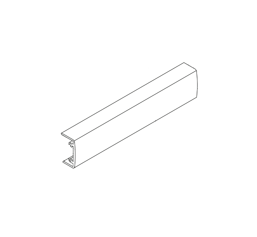
Adams Rite 8099 push bar assembly for narrow stile doors -- horizontal panic bar component used in narrow stile exit device assemblies

Adams Rite 8099 Push Bar Assembly for narrow stile door applications. View product page.


Exit devices are grouped by how they mount to the door and frame and how many latch points they engage. Choosing the right type depends on the door construction, frame material, and project requirements.


Rim Exit Device

A rim exit device mounts on the surface of the door and engages a frame-mounted strike through a single latch point. The chassis attaches to the door face and the latch projects into the strike on the door frame. Rim devices are the most common type and suit most standard commercial steel door and frame applications. They are available in standard panic hardware and fire exit hardware configurations.


Surface Vertical Rod (SVR) Exit Device

An SVR exit device uses external rods that run vertically on the door surface from the device chassis to top and bottom latches. When the bar is pressed, all latch points retract simultaneously. SVR devices suit wide or heavy doors where additional latch points improve security and door stability. The external rods are visible on the door surface.


Concealed Vertical Rod (CVR) Exit Device

A CVR exit device uses internal rods concealed within the door itself, running from the device chassis to top and bottom latches in the door edge. CVR devices require a door prepared with internal rod pockets. They provide a cleaner appearance than SVR devices because the hardware is not visible on the door surface. CVR devices are common in high-end or aesthetic applications where surface hardware is undesirable.


Mortise Exit Device

A mortise exit device integrates with a mortise lock body that is recessed into the door stile. The panic bar retracts the mortise latch when pressed. Mortise exit devices are used on thicker doors and in applications where the additional trim and function options of a mortise lock body are required. They are less common than rim or vertical rod devices in standard commercial applications.


Device TypeLatch PointsRods VisibleTypical Application
Rim1 (frame strike)NoStandard commercial steel doors and frames
SVR3 (top, bottom, latch)Yes -- external rodsWide or heavy doors, higher security requirements
CVR3 (top, bottom, latch)No -- concealed in doorAesthetic applications, doors prepared for concealed rods
Mortise1 (mortise latch)NoThick doors, applications requiring mortise lock functions

For guidance on how to install an exit device in rim, SVR, or CVR configuration, see the exit device installation guide.


Panic Hardware vs Fire Exit Hardware: An Important Distinction
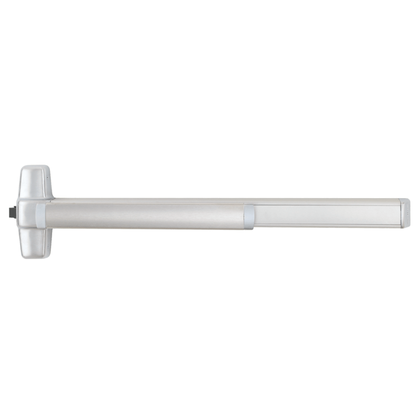
Von Duprin 98/99EO-F Rim Fire Exit Device -- fire exit hardware listed for installation on fire-rated door assemblies

Von Duprin 98/99EO-F Rim Fire Exit Device. Fire exit hardware listed for fire-rated door assemblies. Note the fire label on the device. View product page.


One area where the terminology matters more precisely is the distinction between standard panic hardware and fire exit hardware. These two device types look similar and operate on the same push-to-exit principle, but they serve different applications and carry different code and listing requirements.


Standard Panic Hardware

Standard panic hardware meets the egress hardware requirements of NFPA 101 and the IBC for non-fire-rated doors. It allows single-motion egress without a key and meets the grade and force requirements of ANSI/BHMA A156.3. Standard panic hardware may include a dogging feature that holds the latch retracted, allowing the door to operate as a push-pull door without pressing the bar each time.


Fire Exit Hardware

Fire exit hardware is required on fire-rated door assemblies. A fire-rated door assembly is a door, frame, and hardware combination that has been tested and listed for a specific fire rating (such as 20-minute, 45-minute, 90-minute, or 3-hour). When a fire-rated door requires egress hardware, the hardware must be listed as fire exit hardware to maintain the door's fire rating.

Fire exit hardware carries a fire label issued by a nationally recognized testing laboratory. The device itself must not allow dogging (holding the latch open), because a fire door must be self-latching to contain fire and smoke. This is one of the most important field distinctions: a standard panic hardware device with a dogging feature should not be installed on a fire-rated door in most jurisdictions.

Visually, the device types look nearly identical. The fire label on the device and the order model suffix (typically an "F" designation, such as "EO-F" rather than "EO") are the distinguishing identifiers. If you are replacing hardware on a fire-rated door, confirm that the replacement device carries the correct fire listing.

For a full explanation of fire door ratings and hardware requirements, see the commercial door fire rating guide.


Summary Comparison

FeatureStandard Panic HardwareFire Exit Hardware
Operating principlePush bar releases latchPush bar releases latch
Fire rating labelNot required (non-fire-rated doors)Required -- fire label affixed to device
Dogging featureMay be includedNot permitted -- door must be self-latching
Door applicationNon-fire-rated egress doorsFire-rated door assemblies only
Code term (NFPA 101)"Panic hardware""Fire exit hardware"
Code term (IBC)"Exit device""Fire exit hardware"
Visible identifierNo fire label on deviceFire label affixed to device body


When Is Panic Hardware Required by Code

Both the IBC and NFPA 101 define conditions under which panic hardware or exit devices are required on egress doors. The specific thresholds and occupancy types vary between code editions and are subject to local adoption and amendment. The following is a general summary for context, not a substitute for verifying the applicable code edition and authority having jurisdiction (AHJ) for a specific project.

Under both codes, panic hardware is generally required when an egress door serves an assembly occupancy or an educational occupancy with an occupant load of 50 or more persons. High-hazard occupancies typically require panic hardware regardless of occupant load. The applicable code for your jurisdiction determines the exact threshold and occupancy classifications.

When panic hardware is not code-required, exit devices are still often used on commercial egress doors because they provide convenient, fast egress and are well-suited for high-traffic openings. Code requirement and product choice are two separate decisions: the code determines whether panic hardware is mandatory; the opening conditions determine the best device type when hardware selection is otherwise discretionary.


Occupancy TypeGeneral Code TriggerDevice Type RequiredNote
Assembly (theaters, arenas, auditoriums)Occupant load 50+Panic hardware or fire exit hardwareFire-rated doors need fire exit hardware
Educational (K-12, universities)Occupant load 50+Panic hardware or fire exit hardwareVerify local amendments
High-hazard (certain industrial/storage)Typically any occupant loadPanic hardware or fire exit hardwareCheck applicable code edition
Business, retail, healthcare, governmentNot typically mandated; discretionaryExit device at specifier discretionFire-rated doors still need fire exit hardware

For a more detailed breakdown of panic hardware code requirements and installation conditions, see the panic hardware for commercial doors guide. For ANSI/BHMA grading and standards that govern exit device performance requirements, see the ANSI BHMA hardware standards guide.


Exit Device Mounting Configurations and Strike Hardware
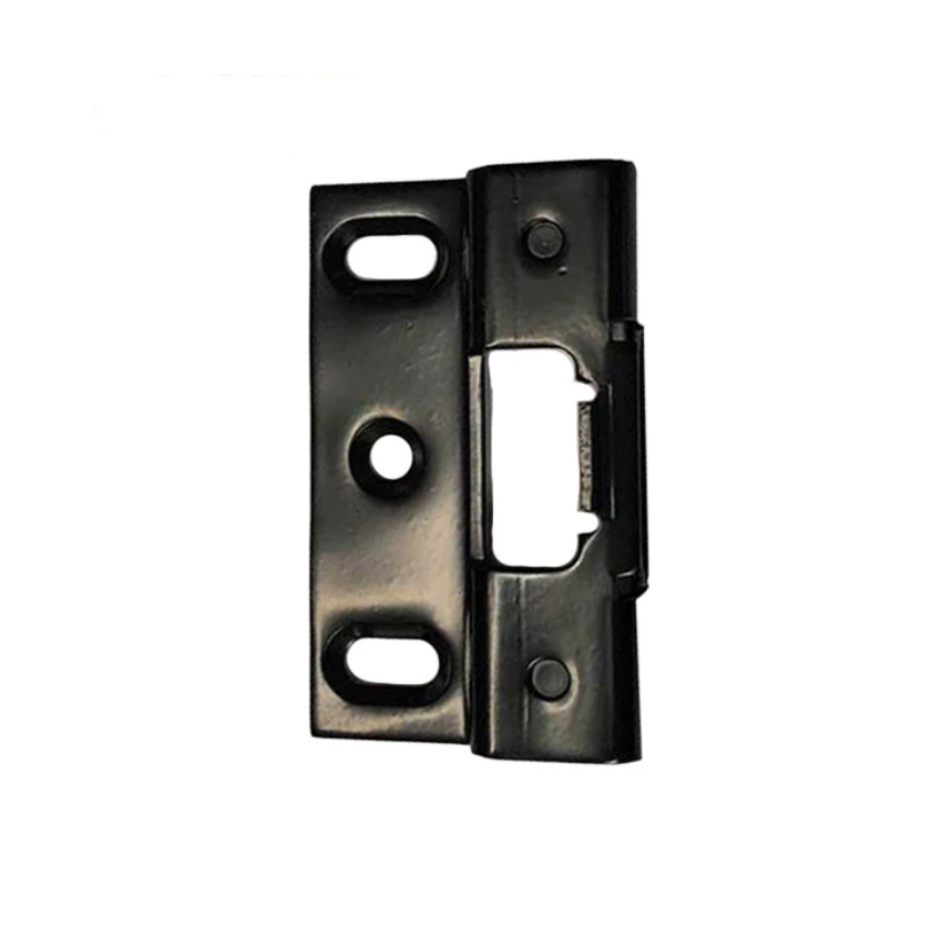
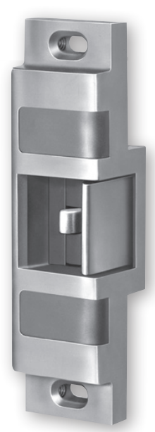
Adams Rite 22-0430 strike for rim exit device -- frame-mounted latch engagement component required for rim exit device installation

Adams Rite 22-0430 Strike for Rim Exit Device. The strike mounts on the door frame and receives the rim exit device latch when the door closes. View product page.


An exit device does not operate alone. The device mounted on the door requires a corresponding component on the door frame to complete the latch engagement. For rim devices, this is a rim strike mounted on the frame or mullion. For vertical rod devices, the top and bottom latches engage in floor and head frame strikes. Matching the correct strike to the device series and configuration is part of the parts ordering process.

Strikes are series-specific. A rim strike for one manufacturer's exit device series may not be compatible with a different series, even if the dimensions appear similar. Always verify the strike model against the device series when ordering replacement hardware.

For access control integration, exit devices can be electrified through electric latch retraction (EL) or connected to an electric strike. The choice between electrifying the device itself versus using an electric strike depends on the security requirements and the control logic of the access control system. For a full explanation of these options, see the access control and commercial door hardware integration guide.


Push Element Options: Bar, Touchbar, and Push Pad

Exit devices do not all use the same style of push element. The horizontal bar is the most common and widely recognized, but buyers will also encounter touchbar and push pad configurations.


Crossbar or Push Bar

The traditional crossbar extends across the full width of the door or at least half the door width as required by code. The bar is the most recognizable style and is used across nearly all device types. Push bars are replaceable components: the bar can be ordered separately to replace a damaged or worn push element without replacing the full device.


Touchbar

A touchbar is a slimmer, low-profile push element that is activated by a lighter touch. Touchbars are used where a sleeker appearance is preferred or where the reduced protrusion into the opening is an advantage. Some exit devices are designed specifically for touchbar configurations.


Push Pad

A push pad is a wider, flat panel that replaces the crossbar. Push pads are used on narrow stile aluminum doors and glass storefront applications where the door stile width does not accommodate a traditional crossbar assembly. The Adams Rite 8099 series is a common example of a narrow stile exit device that uses a push bar assembly sized for aluminum door stiles.


How to Identify Which Device Type You Have

Before ordering any replacement parts or a replacement device, confirm the model number of the installed unit. The model number is printed on a label affixed to the device chassis, typically on the side or back of the housing where it is visible when the door is open. The frame strike or the door edge may also carry a label.

Once you have the model number, confirm:

  • Whether the device is standard panic hardware or fire exit hardware (check for the fire label)
  • The mounting configuration (rim, SVR, CVR, or mortise)
  • The push element style (crossbar, touchbar, or push pad)
  • The outside trim configuration, if any (keylock, cylinder, thumbturn, or exit only)
  • The electrification option, if applicable (EL, QEL, MEL, or standard non-electrified)

These five data points determine the exact parts needed for any repair or replacement. Security Parts stocks exit device parts across multiple series and configurations. For part identification guidance organized by component category, see the exit devices parts guide.


Exit Devices by Building Type

Exit device type and configuration vary by building type, door construction, and code requirements. The following table summarizes common applications.

Building TypeCommon Device ConfigurationFire Rating Consideration
Schools and universitiesRim or SVR, panic hardware or fire exit hardwareCorridor and stairwell doors often fire-rated -- fire exit hardware required
Healthcare facilitiesRim or CVR, fire exit hardware commonHigh proportion of fire-rated doors -- verify each opening
Government buildingsRim or SVR; may include electrified optionsStairwell and rated corridor doors require fire exit hardware
High-rise office buildingsRim or mortise; stairwell re-entry doors need careful specificationMost stairwell doors are fire-rated -- fire exit hardware required
Retail and commercialRim, standard panic hardware; storefront may use narrow stile devicesVaries; verify each opening against door rating
Controlled access and delayed egressDelayed egress exit control lock or electrified exit deviceFire alarm release required; see delayed egress requirements

For application-specific guidance, see the healthcare door hardware guide, the K-12 school door hardware guide, and the government buildings door hardware guide. For delayed egress exit control lock requirements, see what is delayed egress.


Sourcing Exit Device Parts

Security Parts stocks exit device parts across Von Duprin, Falcon, Adams Rite, and Detex product lines. Replacement parts include push bar assemblies, latch assemblies, chassis components, outside trim kits, strike kits, glass bead kits, electrification modules, and dogging hardware.

Parts are series-specific. A Von Duprin 98/99 series push bar assembly is not interchangeable with a Falcon series push bar, even if the devices appear similar from the front. Confirm the device series and model number before ordering. Call 845-935-0301 for pre-order compatibility support if you are uncertain which parts match your installed device.

For the full Von Duprin 98/99 series parts catalog, see the Von Duprin 98/99 series exit device parts guide. For Detex exit control lock parts, see the Detex ECL parts guide. For troubleshooting a device that is not latching, binding, or operating correctly, see the commercial door hardware troubleshooting guide.


About the Author

This guide was written by the Security Parts team, a commercial door hardware specialist serving locksmiths, facilities managers, general contractors, and security integrators since 2001. Security Parts stocks exit device parts across Von Duprin, Falcon, Adams Rite, and Detex product lines, with same-day shipping on stocked components. For related guidance, see the panic hardware for commercial doors guide and the commercial door fire rating guide.
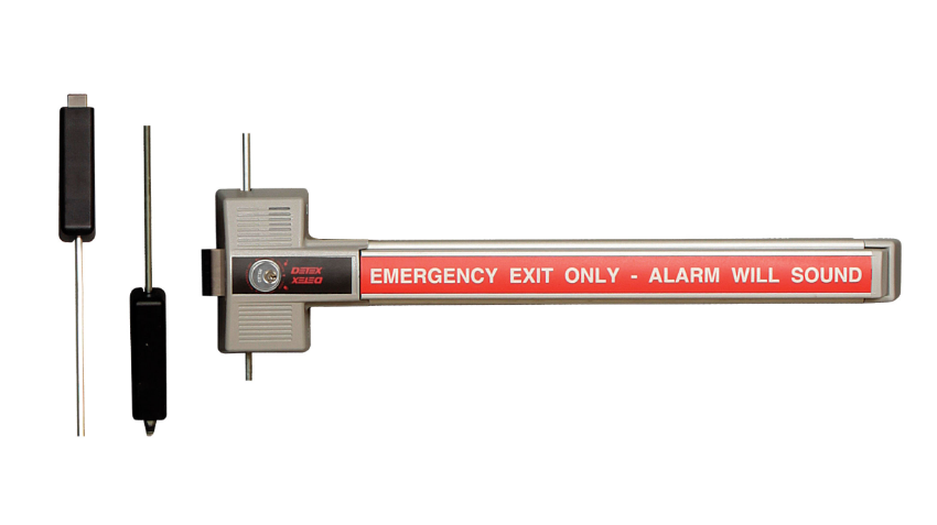
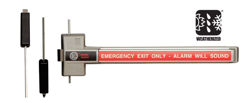
What Is Delayed Egress: How It Works, When Code Requires It, and Which Hardware to Specify

Quick Answer

Delayed egress is a code-permitted door locking system that holds a door locked for a short timed period after someone pushes the exit touchbar. The device triggers a loud audible alarm when touched, then automatically releases the latch and allows free exit after 15 or 30 seconds, depending on the code and occupancy type. It is not a means of preventing egress permanently. It is a life safety compromise that gives facilities time to respond to an unauthorized or unassisted exit attempt while still guaranteeing egress within the code-permitted window.

Delayed egress is most commonly found in memory care units, dementia wards, schools, government buildings, and certain healthcare facilities. It is governed by NFPA 101 Section 7.2.1.6 and IBC Section 1010.1.9.8. All delayed egress devices must release immediately when the fire alarm activates or when power is lost.


How a Delayed Egress Device Works

A delayed egress device looks similar to a standard exit device: a horizontal touchbar or push plate mounted across the door, connected to a latch mechanism that releases when pressed. The critical difference is the internal timing mechanism and alarm circuit.

Here is the sequence of events when someone pushes a delayed egress door:

  • Touchbar contact: The person presses the touchbar or push plate. The door does not open immediately.
  • Alarm activation: Within one second of touchbar contact, a built-in alarm sounds at the door. The alarm is loud enough to alert staff in an adjacent area. Some models also send a signal to a remote annunciator panel.
  • Delay period: The door remains locked during the delay period. Under NFPA 101, the maximum permitted delay is 15 seconds. Under the IBC in jurisdictions that permit an extended delay, the maximum is 30 seconds for approved occupancy types.
  • Automatic release: After the delay period expires, the latch retracts automatically and the door opens freely. The person does not need to maintain pressure on the touchbar throughout the delay. A single push is sufficient to start the timing sequence.
  • Reset: When the door returns to the closed position, the device resets automatically to the locked state, ready for the next cycle.

The device must be powered, typically by 24VDC from the building's security or access control power supply. When power is removed, the device defaults to free egress with no delay (fail-safe). When the fire alarm activates, the device receives a release signal from the fire alarm panel and immediately retracts the latch, bypassing the delay entirely.


NFPA 101 Section 7.2.1.6: Plain-Language Explanation

NFPA 101, the Life Safety Code, is the primary code governing delayed egress in the United States. Section 7.2.1.6 sets the conditions under which a delayed egress locking system is permitted.

In plain terms, the code says the following:

  • The delayed egress system is only permitted where the building is protected throughout by an approved automatic fire suppression system or an approved automatic fire detection system.
  • The maximum delay is 15 seconds from the time the touchbar is pressed until the door releases.
  • The device must sound an audible alarm at the door when the touchbar is pressed.
  • The device must release immediately when the fire alarm system activates anywhere in the building, not just in the zone where the door is located.
  • The device must release immediately when power to the device is lost.
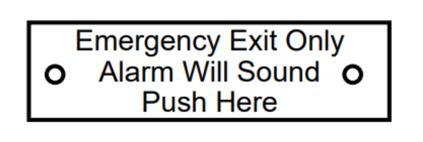
  • The door must be provided with a readily visible posted sign that tells users the alarm will sound and the door will open after the delay period. This sign is not optional.
  • Only one such device may be installed on any egress path, meaning a person cannot be required to pass through more than one delayed egress door before reaching a public way or area of refuge.

The specific occupancy chapters of NFPA 101 also affect where delayed egress is permitted. The general rule in Section 7.2.1.6 permits delayed egress in specific occupancy types. The AHJ has authority to approve or deny the installation based on the occupancy classification and the building's fire protection systems.


IBC Section 1010.1.9.8: Plain-Language Explanation

The International Building Code (IBC), adopted in most US jurisdictions, addresses delayed egress in Section 1010.1.9.8. The IBC provisions are largely consistent with NFPA 101 but include one significant difference: the permitted delay can extend to 30 seconds in specific occupancy types when approved by the AHJ.

In plain terms, the IBC says the following:

  • Delayed egress is permitted only where the building is equipped throughout with an automatic sprinkler system or an approved fire detection system.
  • The locking system must release when a signal is received from the sprinkler system, the fire detection system, or a manual fire alarm initiation device.
  • The system must release upon loss of power controlling the lock.
  • The required signage must be posted on the door at an approved location and in an approved format.
  • A 15-second delay applies by default. A 30-second delay is permitted for Group I-1 (assisted living, residential care), Group I-2 (hospitals, nursing facilities), Group I-3 (detention and correctional facilities), and Group R-1 (hotels) occupancies when specifically approved by the AHJ.
  • Only one delayed egress device may be encountered on any single egress path to the public way.


The 15-Second vs 30-Second Delayed Egress Rule

The distinction between a 15-second and 30-second delay is one of the most common specification questions for delayed egress projects.

Delay SettingCode AuthorityTypical ApplicationAHJ Approval Required
15 secondsNFPA 101, IBC (default)Most commercial, educational, government, and healthcare buildingsYes -- AHJ must approve delayed egress for the occupancy type
30 secondsIBC Section 1010.1.9.8 (extended)Memory care units, dementia wards, assisted living, hospitals, detention facilities, hotelsYes -- AHJ must specifically approve the 30-second delay for the occupancy group

The 30-second delay exists primarily for memory care and dementia applications, where a resident may attempt to exit but will typically stop or turn back within 30 seconds when staff responds. In these settings, a 15-second delay may not give staff adequate response time before the door releases.

The Detex ECL-230X series supports both 15-second and 30-second delay settings. Confirm with the AHJ which setting is approved for the specific occupancy before specifying or installing the device. For detailed parts information on the ECL-230X series, see the Detex ECL parts guide.


Delayed Egress vs Free Egress: What Is the Difference

Detex ECL-230X-TDB 3-point delayed egress exit control lock for commercial doors requiring timed egress

Detex ECL-230X-TDB 3-Point Delayed Egress Exit Control Lock. View product page.


Most commercial exit devices provide free egress: push the bar and the door opens immediately. Delayed egress is a specific modification to that behavior, permitted only in certain building types and only with AHJ approval.


FeatureFree Egress DeviceDelayed Egress Device
Door opens whenImmediately on touchbar contactAfter 15 or 30 seconds
Alarm on touchbar contactNo (dogged devices are silent)Yes -- within 1 second of contact
Fire alarm behaviorNo change (already free egress)Immediate latch release, no delay
Power failure behaviorNo changeImmediate latch release, no delay
Required posted signageStandard exit signage onlyCode-compliant delayed egress sign required
AHJ approvalNot required for standard useRequired for every installation
Occupancy restrictionMost occupancy typesSpecific occupancy types only
Per-egress-path limitNo limitMaximum one delayed egress door per egress path

For broader context on exit device types and how to select the right one for your opening, see the exit devices parts guide and the panic hardware for commercial doors guide.


What Happens During a Fire Alarm, Power Failure, and Reset

Fire Alarm Release

A delayed egress device must be wired to the building fire alarm panel. When the fire alarm activates anywhere in the building, the fire alarm panel sends a release signal to every delayed egress device in the system. All delayed egress doors release immediately and revert to standard push-to-exit operation with no delay and no alarm requirement. This release must happen regardless of whether a touchbar has been pressed or a delay sequence is in progress.

If the building's fire alarm panel trips during an active delay sequence, the delay is cancelled immediately and the door opens. People do not have to wait out the remaining delay during a fire event.

Confirm that the fire alarm integration wiring is completed and tested before the delayed egress system is put into service. A delayed egress device that is not connected to the fire alarm system does not meet the code requirements of NFPA 101 Section 7.2.1.6 or IBC Section 1010.1.9.8 and cannot be legally installed on an egress path.


Power Failure Release

Loss of power to the delayed egress device causes the latch to release and the door to revert to free egress. This fail-safe behavior is required by both NFPA 101 and the IBC. The device cannot hold the door locked without power.

The Detex ECL-230X series operates on 24VDC and requires continuous power to maintain the delayed egress locking function. When power is removed, the device releases within milliseconds and the door operates as a standard push-to-exit device.

Some ECL installations include battery backup to maintain alarm annunciation capability during brief power interruptions. However, battery backup does not change the fail-safe locking behavior: the door must release on power loss, even if the battery is powering auxiliary functions.


Reset After a Delay Cycle

After a completed delay cycle (when someone pushes the bar and the door opens after the delay), the device resets automatically when the door returns to the closed and latched position. No manual action is required to reset the device to the delayed egress state. The device is ready for the next cycle as soon as the door is closed.

Some ECL models require a manual reset by staff using an authorized key or credential if the device has been triggered. Confirm the reset behavior of the specific model when specifying or installing the device, since this affects how staff workflows are designed around the door.


Where Delayed Egress Is Used: Building Types and Applications

Detex ECL-230X-W-TDB weatherized 3-point delayed egress exit control lock for exterior doors and covered egress paths

Detex ECL-230X-W-TDB Weatherized 3-Point Delayed Egress Lock for exterior applications. View product page.


Building TypeTypical ApplicationCommon Delay SettingNotes
Healthcare -- Memory Care and Dementia UnitsPerimeter exit doors, unit entry/exit doors30 seconds (IBC Group I-1/I-2)Most common application; 30-second delay requires AHJ approval
Healthcare -- Hospitals and Nursing FacilitiesPsychiatric unit doors, behavioral health exits15 or 30 secondsDelay setting depends on occupancy classification and AHJ
K-12 SchoolsExterior exit doors, perimeter doors during school hours15 secondsUsed to monitor unauthorized student exits; alarms alert staff
Universities and CollegesDormitory perimeter doors, controlled campus exits15 secondsCommonly installed with access control integration for after-hours monitoring
Government BuildingsControlled area exits, file room perimeter doors15 secondsUsed to monitor exits from restricted areas without fully restricting egress
High-Rise BuildingsStairwell re-entry doors, controlled floor exits15 secondsMust meet NFPA 101 high-rise provisions; fire alarm integration is critical
Retail and CommercialLoss prevention exits, back-of-house egress doors15 secondsAHJ approval required; typically used on secondary egress paths only
Detention and Correctional FacilitiesControlled egress from detention areas15 or 30 seconds (IBC Group I-3)Special IBC provisions apply for this occupancy type

For application-specific guidance on commercial door hardware requirements, see the healthcare door hardware guide, the K-12 school door hardware guide, the universities door hardware guide, the government buildings guide, and the high-rise buildings guide.


Delayed Egress Signage: What the Code Requires

Detex ECL-230X-TB 2-point delayed egress exit control lock for interior commercial door applications

Detex ECL-230X-TB 2-Point Delayed Egress Exit Control Lock for interior applications. View product page.


Both NFPA 101 Section 7.2.1.6 and IBC Section 1010.1.9.8 require that a compliant sign be posted on every delayed egress door. The sign is not optional and is not satisfied by standard exit signage.

The required sign must communicate the following to anyone approaching the door:

  • Pushing the bar will activate an alarm
  • The door will open after a specified number of seconds (15 or 30, as applicable)
  • The information must be clear, readable, and positioned where someone approaching the door will see it before pushing the bar

The Detex ECL-395 series provides code-compliant delayed egress door signs available in multiple languages: English, Spanish, French, French-Canadian, and German. These signs are listed by code as a requirement accompanying every delayed egress installation, not as an accessory upgrade. An installation that has a delayed egress device but lacks the required posted sign fails the code requirements of NFPA 101 and the IBC and will be flagged during any AHJ inspection.

The sign must be inspected annually to confirm it is intact, legible, and properly positioned. A torn, missing, faded, or obstructed sign is a code deficiency even if the device itself is functioning correctly.


2-Point vs 3-Point Delayed Egress: Which Model to Choose

The Detex ECL-230X series is available in two primary locking configurations: 2-point (single latchbolt) and 3-point (top, bottom, and latchbolt). Choosing the correct configuration depends on the door type and the security and code requirements of the opening.


2-Point Delayed Egress (ECL-230X-TB / ECL-230X-W-TB)

Detex ECL-230X-W-TB weatherized 2-point delayed egress exit control lock for exterior commercial door applications

Detex ECL-230X-W-TB Weatherized 2-Point Delayed Egress Lock. View product page.

The 2-point model uses a single latchbolt at the device chassis, engaging one strike point on the door frame. This is the standard configuration for most interior delayed egress applications where the door and frame are in good condition and the single latch is sufficient to hold the door during the delay period. The weatherized version (ECL-230X-W-TB) is appropriate for exterior applications exposed to weather.


3-Point Delayed Egress (ECL-230X-TDB / ECL-230X-W-TDB)

The 3-point model adds top and bottom latching in addition to the chassis latch, providing three points of engagement against the frame. This configuration is used when additional door stability is required during the delay period, when the door gap is inconsistent due to door warping, or when the AHJ or security integrator requires multi-point engagement for higher-security delayed egress applications.

ModelLatch PointsWeatherizedTypical UseProduct Page
ECL-230X-TB2-pointNoInterior doorsView
ECL-230X-W-TB2-pointYesExterior / covered egress pathsView
ECL-230X-TDB3-pointNoInterior doors requiring multi-point engagementView
ECL-230X-W-TDB3-pointYesExterior doors requiring multi-point engagementView

For replacement parts, mechanism assemblies, strike kits, bar components, and accessory kits for all ECL-230X models, see the complete Detex ECL parts guide.


Annual Inspection and Testing Checklist for Delayed Egress Devices

NFPA 101 requires annual inspection and testing of life safety features including delayed egress systems. NFPA 80 also requires annual inspection of fire-rated door assemblies, which includes any delayed egress device installed on a fire-rated door. Written records of each inspection must be maintained and made available to the AHJ upon request.

For the complete commercial door hardware maintenance schedule, see the commercial door hardware maintenance checklist.


Functional Operation Test

  • Push the touchbar and confirm the alarm activates within one second of contact
  • Time the delay from touchbar contact to latch release. Confirm the measured delay matches the programmed setting (15 or 30 seconds)
  • Confirm the door opens freely after the delay period without requiring a second push
  • Allow the door to close and confirm it returns to the latched and delayed egress state automatically


Fire Alarm Release Test

  • With the delayed egress device activated (during the delay sequence), trigger a test signal from the fire alarm panel
  • Confirm the latch releases immediately upon receiving the fire alarm signal
  • Confirm the door operates as a standard free egress device with no delay during the fire alarm signal
  • Reset the fire alarm panel and confirm the delayed egress device returns to normal operation
  • This test must be performed in coordination with the building fire alarm system contractor or the AHJ


Power Failure Release Test

  • Disconnect power to the delayed egress device at the power supply
  • Confirm the latch releases immediately and the door opens freely
  • Reconnect power and confirm the device returns to normal delayed egress operation when the door is closed and latched


Signage Inspection

  • Confirm the required delayed egress sign is present, intact, and legible
  • Confirm the sign is positioned where it is visible to anyone approaching the door from the egress side
  • Confirm the sign specifies the correct delay period (15 or 30 seconds as applicable)
  • Replace any sign that is torn, faded, obstructed, missing, or specifies the incorrect delay period


Physical Inspection

  • Inspect the touchbar or push plate for physical damage, wear, or looseness
  • Check all mounting fasteners for tightness
  • Inspect the strike kit and latch engagement for alignment and wear
  • Confirm the alarm speaker is unobstructed and produces audible output at the required sound level
  • Inspect all wiring connections at the device and at the power supply for corrosion or looseness
  • Document all inspection results and note any deficiencies found and corrected


Where to Source Delayed Egress Hardware and Replacement Parts

Security Parts stocks Detex ECL-230X delayed egress exit control locks in all four configurations (2-point standard, 2-point weatherized, 3-point standard, 3-point weatherized) and stocks 59 ECL-series replacement parts including internal mechanism assemblies, bar and paddle components, strike kits, cover and shield assemblies, outside trim, cylinder components, accessory kits, and code-required delayed egress door signs.

For the complete parts catalog organized by component category, see the Detex ECL parts guide. For general exit device parts and component identification, see the exit devices parts guide. For guidance on exit device installation, see the exit device installation guide. For troubleshooting a delayed egress device that is not functioning correctly after installation, see the commercial door hardware troubleshooting guide.

Call 845-935-0301 for pre-order compatibility support when selecting replacement parts for an existing ECL installation.


About the Author

This guide was written by the Security Parts team, a commercial door hardware specialist serving locksmiths, facilities managers, general contractors, and security integrators since 2001. Security Parts stocks Detex ECL-230X delayed egress exit control locks in all configurations and 59 ECL-series replacement parts, with same-day shipping on stocked components and pre-order compatibility support at 845-935-0301. For related guidance, see the commercial door fire rating guide and the access control and commercial door hardware integration guide.

How to Install an Exit Device: Step-by-Step Guide for Rim, SVR, and CVR Configurations

Quick Answer

Installing an exit device on a commercial door requires four things done in the right order: confirm your device type and handing before touching the door, mount the chassis at the correct height (touchpad centerline between 34 and 48 inches above finished floor per ANSI A156.3), install the appropriate strike for your configuration (rim, surface vertical rod, or concealed vertical rod), and verify latch engagement and egress force before the door goes back into service.

The steps differ for each device type. Rim devices mount at one point; surface vertical rod (SVR) devices require top and bottom rod adjustment; concealed vertical rod (CVR) devices require factory-prepped door pockets. Start with this guide from the beginning so you are following the correct steps for your specific installation.


Before You Start: Identify Your Exit Device Configuration

The most expensive exit device installation mistake happens before the first hole is drilled: a contractor starts the wrong set of steps because they did not confirm the device type. Rim, SVR, and CVR devices share some installation principles but have completely different strikes, rods, and door prep requirements. Confirm your device type first.

Rim exit device on a commercial door showing the chassis mounted to the door face with a single latch point

A rim exit device mounts to the door face and latches at one point. See the exit devices parts guide for component identification.


Rim Exit Device

A rim device mounts directly to the door face and latches at one point only. The strike mounts to the door frame. When the touchpad or crossbar is pushed, the latch retracts and the door swings free. Rim devices are the most common configuration and the simplest to install. Look for a single horizontal crossbar across the door width and a surface-mounted chassis on the door face. Common series identifiers: 98, 99, F-98, F-99, 22, 33A.


Surface Vertical Rod (SVR) Exit Device

A surface vertical rod device latches at two points: a top latch that engages the top frame and a bottom bolt that drops into a floor strike or threshold strike. The rods run vertically on the door face. SVR devices are used on doors without a center mullion or on pairs of doors where the active leaf requires multi-point latching. Look for exposed vertical rods running from the chassis to the top and bottom of the door. Common series identifiers: 9827, 9927, 27-series.


Concealed Vertical Rod (CVR) Exit Device

A concealed vertical rod device also latches at top and bottom, but the rods run inside the door cavity rather than on the surface. CVR installations require the door to have factory-prepped mortise pockets for the top latch assembly and a cutout for the bottom bolt. If the door does not arrive pre-prepped, field prep is significantly more involved. Look for a device with no visible rods on the door face. Common series identifiers: 9847, 9947, 47-series.

For help identifying which exit device series is installed or which series to order for a replacement, see the Von Duprin exit device series comparison and the Von Duprin panic bar selection guide.


What You Need: Tools and Materials Checklist

Required Tools

  • Drill with bit set (1/4-inch and 3/8-inch bits for through-bolt applications)
  • Tape measure
  • 4-inch torpedo level or longer spirit level
  • Pencil or punch awl for marking
  • Phillips and flathead screwdrivers
  • Allen/hex key set (for dogging slot and trim screws)
  • Nut driver or adjustable wrench (for through-bolt nuts)
  • Threadlocker compound (for through-bolt applications on hollow metal doors)
  • Chisel (for CVR top latch pocket if door is not pre-prepped)
  • Center punch (for accurate pilot hole placement on metal doors)


Materials to Have On Hand Before Starting

  • Exit device with all included hardware (confirm nothing is missing before opening the door)
  • Manufacturer installation template for the exact series being installed
  • Correct strike for the device series (rim strike, top strike, bottom strike/floor box as applicable)
  • Through-bolt kit if the door does not include it
  • Backplate (required on thin hollow metal doors to prevent chassis deformation)
  • For SVR: additional rod length if the door is taller than standard
  • For CVR: edge prep kit if the top latch pocket is not factory-installed


Pre-Install Inspection Checklist

Running through this checklist before mounting prevents the two most common failed installations: wrong handing and a device that does not match the door prep. Both require sending the device back for exchange, which costs more time than checking takes.


Confirm the Handing

Stand inside the room facing the door from the secure side, meaning the side the door swings away from you. If the hinges are on your right, the door is right-hand (RHR or RH). If the hinges are on your left, the door is left-hand (LHR or LH). The handing of the exit device must match the door handing.

The handing designation is printed on the device carton label and on the chassis identification label inside the device. Confirm the carton label matches the door before opening packaging. Some exit device series are field-reversible by flipping the latch or lever trim; others are factory-handed and cannot be changed in the field. If the handing is wrong on a non-reversible device, do not mount it. Contact the supplier before proceeding.


Confirm the Door Prep

  • Door width: Confirm the chassis length fits the door width. Most exit devices are available in standard widths (typically 36-inch and 48-inch door widths). A chassis that overhangs the door edge will not mount correctly.
  • Door thickness: Through-bolt lengths and faceplate depths are door-thickness specific. Confirm the through-bolt length in the kit matches the actual door thickness before drilling.
  • For CVR devices: Confirm the top latch mortise pocket dimensions and the bottom bolt cutout match the device specification. Measure the pocket depth, width, and location against the manufacturer template before mounting the chassis.
  • For SVR devices: Confirm the rod lengths shipped with the device match the door height. Rods ship at maximum length and must be cut or adjusted down.


Inspect the Device Before Mounting

  • Check the touchpad or crossbar for shipping damage (bent bar, cracked end cap, missing trim screws)
  • Confirm latch projection by measuring from the latch face to the device faceplate. Standard latch projection is 5/8 inch. Confirm this matches the strike clearance on your frame.
  • Verify that all rods, end caps, trim screws, through-bolts, and the installation template are in the packaging
  • Confirm the included strike matches the device series. Strikes are series-specific and not interchangeable between device families


Exit Device Mounting Height Requirements

Mounting height is the most-searched specific installation question for exit devices, and the most common source of a code-noncompliant installation.

ANSI A156.3 Height Requirement

ANSI A156.3 requires the touchpad or crossbar centerline to be between 34 and 48 inches above the finished floor. This measurement is taken to the push element itself, not to the device chassis or the top of the touchbar. A device chassis mounted with its center at 38 inches may have a touchpad centerline at 36 inches, depending on the chassis design. Always measure to the push element after mounting, not to the chassis center.

The 34-to-48-inch range also satisfies ADA Section 404.2.7 for accessible door hardware. An exit device within this range does not require an additional accessible pull or lever on the push side.


Mounting Height Reference by Door Height

Door HeightRecommended Chassis Mounting CenterPush Element Centerline Target
7 ft (84 in)38--40 in from finished floor36--40 in (verify after mounting)
8 ft (96 in)38--42 in from finished floor36--42 in (verify after mounting)
9 ft (108 in)40--44 in from finished floor38--44 in (verify after mounting)
Any heightAdjust to keep push element within 34--48 in34--48 in (ANSI A156.3 absolute range)

For ANSI and BHMA hardware standard context, see the ANSI/BHMA door hardware standards guide.


Marking the Mounting Height on the Door

Use the manufacturer installation template for your device series. Position the template at the target height with the push element centerline mark at the intended measurement. Confirm the template is level before marking any holes. Mark all hole center points with a pencil or punch awl before drilling. On metal doors, use a center punch to prevent bit walk when drilling.


Metal Door vs Wood Door Installation Differences

Hollow Metal Door Installation

Through-bolt mounting is required on hollow metal (HM) doors. The hollow interior of the door does not provide enough thread engagement for wood screws or short machine screws to resist the repeated lateral force applied to the exit device during daily egress cycles. Through-bolts pass completely through the door and are secured with nuts on the interior face.

  • Use the through-bolt kit supplied with the device or ordered separately for the series
  • A backplate on the interior door face is required on thin hollow metal doors (typically 14 gauge or thinner) to prevent the through-bolt nuts from pulling through the door face under load
  • Apply threadlocker compound to through-bolt threads before tightening. Vibration from repeated door operation can loosen nuts over time without it
  • Tighten nuts to the manufacturer-specified torque (typically 60--80 in-lb). Do not over-tighten, which can deform the chassis or door face


Wood Door Installation

Solid core wood doors can use the machine screws provided with the exit device in most cases. However, through-bolt mounting is still recommended on high-cycle openings or any door that will see heavy commercial traffic.

  • Pilot holes should be drilled at 70--80% of the screw diameter to prevent splitting on solid wood doors
  • Minimum door thickness for adequate thread engagement is typically 1-3/4 inches. Confirm the fastener length in the kit is appropriate for the actual door thickness
  • On doors with veneer or laminate faces, over-tightening can crack or delaminate the surface. Tighten just until the chassis is firmly seated


Aluminum Storefront and Glass Doors

Exit devices on aluminum storefront frames require a device series specifically listed for that door and frame type. Standard exit device hardware is not designed for narrow stile aluminum extrusions. Glass doors with patch fittings require a device series compatible with the patch dimensions. Confirm the device series listing before ordering for any aluminum or glass door application.


How to Install a Rim Exit Device (Step by Step)

Rim installation is the most straightforward of the three device types. The device mounts to the door face with through-bolts, and the rim strike mounts to the door frame. For Von Duprin 98/99 series rim device components, see the Von Duprin 9899 series parts guide. For Falcon 19, 24, and 25 series rim devices, see the Falcon 19/24/25 series exit device parts guide.


Step 1: Prepare the Door and Apply the Template

Position the manufacturer installation template on the door face at the target mounting height. The template shows the hole pattern for the specific device series. Confirm the template is oriented correctly for the door handing (RHR or LHR). Use the template center marks to align the push element centerline at the intended height. Hold the template in position and mark all hole centers with a pencil. Confirm the level before marking.


Step 2: Drill Mounting Holes

On hollow metal doors, use a center punch at each marked location before drilling to prevent bit walk. Drill pilot holes for through-bolts using the bit diameter specified in the installation template (typically 1/4 inch for standard through-bolts). On wood doors, drill pilot holes at 70--80% of screw shank diameter. Clear all chips before proceeding.


Step 3: Mount the Chassis to the Door Face

Set the device chassis against the door face with all holes aligned. Insert through-bolts (or screws on wood doors) through the chassis and door. Start all fasteners before tightening any of them. Once all fasteners are started, tighten in a cross pattern to draw the chassis evenly against the door face without rocking. Apply threadlocker to through-bolt threads on metal doors before tightening the nuts.


Step 4: Install the Rim Strike on the Door Frame

Hold the door in the closed position and mark the strike location on the door frame by pressing the door gently against the frame and transferring the latch centerline. The rim strike must align with the latch both vertically and laterally. Fasten the strike to the frame with the provided fasteners. Most rim strikes have slotted holes for minor vertical adjustment.


Step 5: Set the Latch Projection and Strike Alignment

Close the door and observe how the latch enters the strike. The latch should enter cleanly and engage the strike keeper without rolling back or dragging on the strike lip. If the latch rolls back (does not engage), the strike is too far from the frame face. If the latch drags, the strike is too close or misaligned vertically. Adjust strike position as needed and re-fasten.


Step 6: Secure All Fasteners and Verify Operation

Fully tighten all through-bolt nuts and mounting screws. Operate the touchpad 10 times in succession and confirm the latch retracts fully and consistently each time. Confirm the door latches fully when closed without requiring any pressure on the door face. Proceed to the post-install testing checklist.


How to Install a Surface Vertical Rod (SVR) Exit Device (Step by Step)

SVR installation adds two additional steps to the rim process: top and bottom rod length adjustment. The rods ship at maximum length and must be shortened or adjusted to the actual door height. For Von Duprin 22-series, 33A, 35A, and 55-series SVR devices, see the Von Duprin 22/33A/35A/55 series exit device parts guide.


Step 1: Prepare the Door and Confirm Rod Lengths

Apply the installation template at the target mounting height and mark all chassis holes. Before drilling, hold the device against the door and extend the top rod toward the top frame and the bottom rod toward the floor. Confirm the rods reach their respective strikes with the device chassis at the target mounting position. If the door height is less than the maximum rod length, note the adjustment needed.


Step 2: Mount the Chassis to the Door

Follow Steps 1 through 3 from the rim installation procedure above. The chassis mounting process is identical. Confirm the chassis is level before fully tightening through-bolt nuts.


Step 3: Attach and Adjust the Top Rod Assembly

Connect the top rod to the chassis rod connection point. Run the rod toward the top of the door. Most SVR top rods have a threaded coupler at the strike end that allows length adjustment. Thread the coupler in or out until the top latch engages the top strike correctly when the touchpad is released. Confirm the top latch retracts fully when the touchpad is pressed.


Step 4: Attach and Adjust the Bottom Rod Assembly

Connect the bottom rod to the chassis and run it toward the floor. The bottom rod connects to the floor bolt, which drops into a floor strike or threshold strike. Adjust the rod length so the floor bolt drops cleanly into the floor strike and engages fully when the touchpad is released. The bottom bolt should retract fully when the touchpad is pressed. Confirm both rod connections are tight after adjustment.


Step 5: Install Top and Bottom Strikes

Install the top strike in the header frame at the height required to align with the top latch centerline. Install the floor strike (or threshold strike) at the floor position aligned with the bottom bolt centerline. Both strikes typically have slotted mounting holes for minor alignment adjustment.


Step 6: Set Rod Tension and Test Both Latch Points

Operate the touchpad and confirm both the top latch and the bottom bolt retract simultaneously and fully. Close the door and confirm both latch points engage their respective strikes cleanly. Adjust top or bottom rod length if either latch point drags, rolls back, or fails to engage fully.


How to Install a Concealed Vertical Rod (CVR) Exit Device (Step by Step)

Von Duprin 9947 concealed vertical rod exit device showing the chassis and internal rod configuration for commercial door installation

Von Duprin 98/9947 CVR exit device. Rods are concealed inside the door cavity. View product page. For all CVR replacement parts, see the Von Duprin 9947 CVR exit device parts guide.


CVR installation is the most complex of the three types because the rods run inside the door cavity and the door must be pre-prepped with specific pockets and cutouts. Do not attempt CVR installation on a door that has not been factory-prepped or field-prepped to the manufacturer's specifications.


Step 1: Confirm Door Prep (Top Latch Pocket and Bottom Bolt Cutout)

Measure the top latch mortise pocket (typically at the top of the door edge) against the manufacturer's dimension specifications. Confirm the pocket depth, width, and distance from the door top match the CVR device requirements. Measure the bottom bolt cutout at the door bottom edge and confirm it aligns with the floor strike location. If either prep dimension is incorrect, field modification is required before mounting the chassis.


Step 2: Mount the Chassis to the Door

Apply the installation template and mark all chassis mounting holes. Drill and mount the chassis using the same through-bolt process as rim and SVR installation. Confirm the chassis is level and fully seated before tightening.


Step 3: Route and Connect the Top Latch Assembly

Feed the top latch assembly up through the door cavity to the top latch pocket. Connect the top rod to the chassis drive mechanism and route it through the door interior. Seat the top latch housing in the top pocket and fasten it according to the manufacturer specification. Confirm the top latch retracts when the touchpad is pressed and extends fully when released.


Step 4: Route and Connect the Bottom Bolt Assembly

Feed the bottom bolt assembly down through the door cavity to the bottom cutout. Connect the bottom rod to the chassis drive and route it to the bottom bolt housing. Seat the bottom bolt housing in the bottom cutout and fasten it. Confirm the bottom bolt drops fully when the touchpad is released and retracts fully when the touchpad is pressed.


Step 5: Install Top and Bottom Strikes

Install the top strike in the header frame at the correct height for the top latch centerline. Install the floor strike aligned with the bottom bolt centerline. Both strikes must account for the latch projection depth of the CVR device, which may differ from the SVR projection depth on the same door configuration.


Step 6: Check Bolt Engagement and Adjust

Close the door and verify that both latching points engage cleanly. Cycle the touchpad 10 times and confirm both the top latch and bottom bolt retract and extend consistently. Adjust rod connections at the chassis if either bolt is not traveling the full stroke. Confirm all interior fasteners on the latch and bolt housings are tightened before final inspection.


Dogging the Exit Device After Installation

Von Duprin 090040 hex dogging shaft package used to dog an exit device in the unlocked position    Von Duprin 107813 cylinder dogging kit for key-operated mechanical dogging on commercial exit devices

Left: Von Duprin 090040 hex dogging shaft. Right: Von Duprin 107813 cylinder dogging kit. Both are used for mechanical dogging on standard (non-fire-rated) openings.


Dogging holds the exit device latch in the fully retracted position so the door operates as a standard push-pull door without requiring touchpad pressure. It is typically engaged during business hours and released after closing. Dogging is set after installation, not before.


What Dogging Does

When the latch is dogged, the touchpad or crossbar is held in the depressed position mechanically. The door swings freely in both directions without any requirement to push the touchpad. This is the normal daytime operating mode for high-traffic openings that do not require controlled egress during business hours.


Mechanical (Hex Key) Dogging

The dogging slot is located on the face of the chassis near the touchpad connection. Insert a 3/32-inch hex (Allen) key into the dogging slot and turn it to lock the touchpad in the depressed position. The hex key is removed after dogging; the device stays dogged until the key is reinserted and turned to release.

Mechanical dogging is not permitted on fire-rated openings. A fire door must self-latch every time it closes, and mechanical dogging defeats that requirement. If a fire-rated opening needs free-swing daytime operation, electric dogging is the only compliant option.


Electric Dogging (QEL and MEL Options)

Electric dogging uses an internal solenoid to hold the latch retracted under access control command. When power is cut or the fire alarm triggers, the solenoid releases and the device returns to full latching function. QEL (quiet electric latch retraction) and MEL (motor-driven electric latch retraction) are the two common electric dogging options. For the difference between the two and which to specify, see the Von Duprin QEL vs MEL guide and the access control and commercial door hardware integration guide.


Electric Strike Alignment for Exit Devices

When an exit device is paired with an electric strike for access control, the strike and the device latch must be aligned before the installation is complete. Misalignment is the most common cause of a latch that functions correctly under hand operation but fails to engage reliably under normal door operation. For electric strike replacement parts, see the electric strike parts guide.


Rim Device and Electric Strike Alignment

The rim strike cutout must align with the rim latch both laterally and vertically. With the door in the closed position, confirm that the latch centerline aligns with the center of the electric strike keeper opening. Most electric strikes have a small adjustment range within the frame pocket. Use this range to center the keeper on the latch before final fastening.


Vertical Rod Device and Electric Strike

On SVR and CVR installations, the electric strike typically electrifies only the top latch. The bottom bolt remains mechanical and always extends when the door closes. The top latch alignment process is the same as for a rim device: confirm the top latch centerline aligns with the electric strike keeper centerline before final fastening. The bottom floor strike is installed mechanically and does not require electrical connection.


Testing the Strike and Device Together

Before energizing the strike, confirm the latch enters the keeper cleanly under manual door operation. Then energize the strike and test the following: the touchpad releases the latch while the strike is energized (the latch must retract even though the strike is holding it); the door opens when power is cut (fail-safe) or when the touchpad is pressed while the strike is powered (fail-secure). See the how to install an electric strike guide for detailed wiring and alignment procedure.


Fire-Rated Door Exit Device Installation Requirements

Fire-rated openings carry additional installation rules that are not optional. A standard panic hardware installation that violates any of these requirements fails the fire door assembly certification. For the full fire door hardware context, see the commercial door fire rating guide.
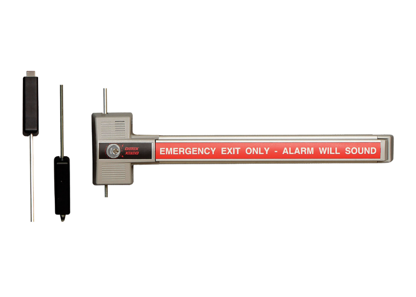
 

Fire Exit Hardware vs Panic Hardware

Exit devices on fire-rated doors must be UL listed fire exit hardware. Standard panic hardware does not carry a fire listing and cannot be substituted. The UL fire listing label appears on the device chassis and on the packaging. It identifies the specific fire door assembly types the device is tested for. Confirm the device's fire listing before installing on any fire-rated opening. For guidance on when panic hardware is required and the distinction from fire exit hardware, see the panic hardware for commercial doors guide.


No Mechanical Dogging on Fire-Rated Openings

Mechanical dogging (hex key or thumbturn dogging) is not permitted on fire-rated openings. It prevents the device from self-latching when the door closes, which voids the fire rating of the assembly. The only compliant option for free-swing operation on a fire door is electric dogging (QEL or MEL), which releases automatically when power is cut or when a fire alarm signal is received.


Coordinator and Closer Requirements on Paired Fire Doors

Fire-rated pairs of doors require a door coordinator that sequences the closing of the active and inactive leaves. Without a coordinator, the active leaf may close before the inactive leaf and prevent full latching. A door closer is also required on every fire-rated exit device opening. The closer must be listed for fire-rated assemblies and set to close and latch the door fully from any open position.


Post-Install Testing Checklist

Run through this checklist before considering the installation complete. Every item here reflects either a code requirement or a common failure mode that is easier to catch now than after the door has been in service.


Functional Egress Test

  • Apply egress force to the touchpad and confirm the latch retracts. Maximum actuating force is 15 pounds for standard devices (30 pounds for fire-rated devices) per ANSI A156.3
  • Push the door open from the fully closed position and confirm it swings to full open without binding
  • Release the touchpad and allow the door to close. Confirm it latches fully without requiring additional force on the door face


Latch Projection and Strike Engagement Check

  • Measure the latch projection from the device faceplate face. Confirm it matches the specification (typically 5/8 inch)
  • Observe the latch entering the strike from the side if possible. The latch tip should enter the keeper cleanly without rolling back on the strike lip
  • Check for any rattle of the latch in the strike keeper. A rattle indicates insufficient keeper depth or a worn latch


Dogging Function Test

  • Insert the hex key and dog the device. Confirm the touchpad stays in the depressed position without the hex key
  • Operate the door as push-pull and confirm it swings freely in both directions
  • Insert the hex key and release the dogging. Confirm the latch returns to the extended position and the touchpad operates normally


Electric Strike Test (If Applicable)

  • Fail-safe: cut power to the strike and confirm the door opens freely
  • Fail-secure: restore power and confirm the door holds when pulled from outside
  • Exit release: with the strike powered, push the touchpad and confirm the latch retracts and the door opens
  • Confirm the strike solenoid does not buzz, click excessively, or produce heat above ambient after 60 seconds of operation


Fire Door Compliance Check (If Applicable)

  • Confirm no hex key or mechanical dogging block is in place
  • Open the door to 90 degrees and release it without assistance. Confirm the door closes fully and latches without any manual intervention
  • Confirm the door coordinator sequences the leaves correctly on pairs (inactive closes before active)
  • Confirm the door closer is set to pull the door to positive latch from any open position between 5 and 90 degrees


Common Exit Device Installation Mistakes

These are the installation errors that result in a callback, a failed inspection, or a code violation. Each one is preventable with the pre-install checklist above.


Installing the Wrong Handing

The device chassis is mounted upside-down or mirrored relative to the door handing. The touchpad ends up on the wrong side of the door, the latch points the wrong direction, or the trim does not align. Catch this during the pre-install handing check before any holes are drilled. If the device is not field-reversible, a factory exchange is the only resolution.


Measuring Mounting Height to the Chassis Instead of the Push Element

The ANSI A156.3 requirement is for the push element centerline, not the chassis center. A chassis center at 40 inches does not guarantee the touchbar centerline is at 40 inches. Measure to the touchpad or crossbar after mounting and confirm the push element is within the 34-to-48-inch range before final fastening.


Using Screw Mounting on a Hollow Metal Door

Short machine screws or wood screws in a hollow metal door do not have enough material engagement to resist repeated egress force. The screws pull out over time, the chassis loosens, and the device fails to function reliably. Through-bolt mounting with a backplate is required on all hollow metal door installations.


Using the Wrong Strike for the Device Series

Exit device strikes are series-specific. A strike from a different series may appear to fit physically but will have a different keeper depth or latch engagement geometry that causes latch rollback. Always confirm the strike part number matches the device series before ordering.


Skipping Rod Length Adjustment on SVR Devices

SVR rods ship at maximum length. Installing them without adjustment for the actual door height results in rods that bottom out before the chassis is fully seated, or rods that are too long and prevent the bottom bolt from dropping fully into the floor strike. Always measure and adjust rod length to the actual door height before mounting the chassis.


Mechanical Dogging on a Fire-Rated Opening

Applying mechanical dogging on a fire-rated exit device opening voids the fire door assembly certification and creates a life safety violation. If the opening requires free-swing daytime operation and carries a fire rating, order a device with QEL or MEL electric dogging before installation.


Omitting the Through-Bolt Nuts or Skipping Threadlocker

Through-bolts inserted without nuts, or nuts tightened without threadlocker on metal doors, loosen from vibration within weeks of installation. The chassis develops play, the latch alignment drifts, and the device requires reinstallation. Apply threadlocker before tightening all through-bolt nuts.


Troubleshooting Exit Device Installation Problems

For broader commercial door hardware troubleshooting guidance, see the commercial door hardware troubleshooting guide.

Touchpad Is Hard to Push

The most common cause is a chassis that is not seated flat against the door face. If the chassis is bowed or misaligned, the touchpad pivot binds against the chassis frame. Check that through-bolts are tightened evenly and that the chassis face is flush against the door. Over-tightened through-bolts can deform thin door faces and cause the same symptom; back off the nuts slightly and recheck.


Latch Does Not Engage the Strike When the Door Closes

Vertical or lateral misalignment between the latch and the strike keeper is the most likely cause. Mark the latch position on the strike face by applying chalk or crayon to the latch tip and closing the door once. The mark on the strike shows whether the latch is hitting above, below, or to the side of the keeper opening. Adjust the strike position accordingly.


Door Does Not Latch After Closing (SVR or CVR)

If the top or bottom latch point is not engaging after the door closes, the rod length is typically the problem. The rod may be too short (latch does not reach the strike) or too long (the rod is buckling before the latch fully extends). Adjust the threaded coupler at the rod connection point in small increments and retest after each adjustment.


Exit Device Rattles or Has Play After Mounting

Through-bolt nuts that are not fully tightened, or a backplate that is missing on a thin hollow metal door, are the two most common causes. Tighten all nuts to the specified torque and confirm the backplate is installed and seated. If play persists after tightening, inspect the chassis mounting holes for elongation, which indicates the door material has been overloaded and needs reinforcement.


Device Is Handed Incorrectly After Mounting

If the touchpad is on the correct side but the latch projects in the wrong direction, check the manufacturer documentation for field-reversibility. Some device series allow the latch to be reversed by repositioning a single component; others require a full exchange. Contact 845-935-0301 for part exchange support before disassembling the device chassis.


Maintenance After Installation

For a complete annual maintenance schedule for all commercial door hardware, see the commercial door hardware maintenance checklist.


Initial 30-Day Inspection

High-traffic doors should receive a 30-day check after installation. Re-check all through-bolt torque after the first month of use. On SVR devices, re-check rod length adjustment after the first month, since rod connection points can shift slightly during initial traffic cycles. Confirm latch engagement has not drifted from the initial setting.


Annual Inspection Points

  • Touchpad pivot wear: apply slight lateral pressure to the touchpad. Any lateral movement beyond minimal play indicates pivot bushing wear
  • Latch bolt engagement depth: confirm the latch still engages the strike keeper fully. A worn latch tip can reduce engagement depth over time
  • Rod connection points (SVR and CVR): confirm rod couplers and connection fasteners are tight and rods have not shifted from adjusted length
  • Strike alignment drift: recheck latch-to-strike alignment with the chalk test annually on high-cycle doors
  • Dogging mechanism: confirm hex key dogging engages and releases without binding
  • Egress force: retest actuating force with a pull scale and confirm it remains below 15 pounds (30 pounds on fire doors)


NFPA 80 Fire Door Inspection Requirements

NFPA 80 requires annual inspection and documentation for all fire-rated door assemblies, including the exit device, hinges, closer, and frame. The inspection must confirm self-latching function, correct device operation, absence of mechanical dogging, and that no components have been modified or replaced with non-listed parts. A written record of each inspection must be maintained.


Where to Source Exit Device Parts and Replacements

Security Parts stocks exit device parts across Von Duprin, Falcon, and other commercial hardware lines. For parts by device type, see the exit devices parts guide and the commercial exit device parts guide. For OEM versus aftermarket guidance before ordering replacement components, see the OEM vs aftermarket commercial door hardware guide.

Call 845-935-0301 for pre-order compatibility support when you need to confirm a part number against the installed device.


About the Author

This guide was written by the Security Parts team, a commercial door hardware specialist serving locksmiths, facilities managers, general contractors, and security integrators since 2001. Security Parts stocks exit device parts across Von Duprin, Falcon, and other commercial hardware lines, with same-day shipping on stocked components and pre-order compatibility support at 845-935-0301. For related installation guidance, see how to install a commercial door closer and commercial door hardware replacement and repair guide.

Schlage N123 Parts Guide: Keycam Assemblies, Plunger Assemblies, and Replacement Components

Quick Answer

The Schlage N123 is an NDE series wireless cylindrical lock. Before ordering any Schlage N123 parts, confirm three things:

  • Confirm the model is N123, not N523. Both are NDE wireless locks, but they use different part numbers. The N123 and N523 keycam and plunger assemblies are not interchangeable. The model number is printed on the back of the inside trim or in the project hardware schedule.
  • Keycam assemblies: 12 N123 keycam assemblies are stocked, each corresponding to a specific lock function. The part number encodes the function. Replacing a keycam with the wrong function code changes how the lock operates.
  • Plunger assemblies: Five plunger types are stocked: push button, push-turn button, spanner button, emergency turn button, and emergency button. The correct type matches the inside trim of the installed lock.
  • 21 Schlage N123 parts are stocked at Security Parts across keycam assemblies, plunger assemblies, the RX switch upgrade kit, HSLR screwpack, and mounting screw.

Call 845-935-0301 for pre-order compatibility support before placing your order.


What the Schlage N123 Is

The Schlage N123 is part of the NDE series, Schlage's wireless cylindrical lock platform designed for access control integration in commercial and institutional buildings. NDE locks communicate wirelessly with the access control system through a credential reader built into the outside trim, eliminating the need for data wiring at each door.

The N123 is configured for applications where the door or lock geometry differs from the standard N523 configuration. While both models are NDE wireless cylindrical locks, they use different internal components. The keycam assemblies, plunger assemblies, and other trim parts are specific to each model and cannot be substituted between them.

The N123 is commonly found in healthcare facilities, educational buildings, and government offices where wireless access control was installed during construction or renovation. Replacement parts are ordered when a keycam wears or fails (most often seen as difficulty retracting the latch with a key), when a plunger assembly needs replacement due to physical wear or button malfunction, or when the access control integrator adds an RX switch function to the existing installation.

The N123 is also an appropriate replacement lock when a facility is upgrading from an older Schlage ND Series cylindrical lock (non-wireless) to the NDE wireless platform on doors where the physical prep does not accommodate the standard N523. Because the NDE platform integrates directly with credential management systems, the parts that control the mechanical function of the lock, particularly the keycam and plunger, are specified at the time of installation to match the access control behavior required at each opening. Replacing any of these components requires confirming both the mechanical part number and the intended lock function before ordering.

For the companion guide covering the N523 model, see the Schlage NDE wireless lock parts guide. That guide covers N523-specific keycam assemblies, cylinder options, and tailpiece configurations, which are not applicable to the N123.


How to Confirm You Have an N123, Not an N523

Ordering parts for the wrong NDE model is the most common ordering error on N123 service calls. Before placing any order, confirm the model number using one of these methods:

  • Label on the inside trim: Remove the inside trim rose cover. The model number is typically printed or stamped on the back of the inside escutcheon or the lock chassis.
  • Hardware schedule: The original project hardware schedule submitted during construction specifies the exact model number for each opening. This is the most reliable source for facilities teams managing a building with a consistent hardware specification.
  • Work order documentation: If the installation was performed under a service contract, the original work order typically records the lock model and function code for each door.

If the model number is not accessible from any of these sources, call 845-935-0301. The Security Parts team can help identify the correct model based on part numbers already installed or hardware schedule details.


Schlage N123 Keycam Assemblies

Schlage N123-076 keycam assembly replacement part for Schlage N123 NDE wireless cylindrical lock

Schlage N123-076 Keycam Assembly. View product page and order.


The keycam assembly is the internal mechanical component that translates key cylinder rotation into latch retraction. The keycam part number specifies both the physical geometry and the lock function (storeroom, classroom, office, etc.). Using a keycam with the wrong function code causes the lock to operate incorrectly, so the replacement must match the installed function exactly.

Twelve N123 keycam assemblies are stocked at Security Parts, covering the complete range of standard functions available for the N123 wireless lock.

Part NumberProduct Page
N123-076 Keycam AssemblyView and order
N123-097 Keycam AssemblyView and order
N123-013 Keycam AssemblyView and order
N123-098 Keycam AssemblyView and order
N123-012 Keycam AssemblyView and order
N123-011 Keycam AssemblyView and order
N123-055 Keycam AssemblyView and order
N123-094 Keycam AssemblyView and order
N123-008 Keycam AssemblyView and order
N123-059 Keycam AssemblyView and order
N123-010 Keycam AssemblyView and order
N123-007 Keycam AssemblyView and order
N123-045 Keycam AssemblyView and order


Keycam replacement is the most common mechanical service call on the N123. The symptom is typically that the key will not retract the latch, or that it retracts with significantly more force than normal. This indicates that the keycam follower or the cam itself has worn past the service threshold. In high-turnover institutional environments, keycam wear is accelerated by the volume of key turns and the frequency of forced or rushed key operation by staff and students. A worn keycam that is not replaced promptly increases wear on adjacent components, including the cylinder and the latch chassis.

When replacing a keycam assembly, confirm the function code of the installed keycam before ordering. The function code determines how the lock responds to a key turn: whether the latch retracts freely, requires a credential to unlock first, or remains locked regardless of credentials. An incorrect keycam function changes the security behavior of the door.


Schlage N123 Plunger Assemblies

Schlage N123-087 spanner button plunger assembly replacement for Schlage N123 NDE wireless lock

Schlage N123-087 Spanner Button Plunger Assembly. View product page and order.


The plunger assembly controls the inside button or thumbturn mechanism of the N123. Five plunger assembly types are stocked, each corresponding to a different inside trim configuration. The correct replacement must match the existing inside button type exactly, because the plunger geometry is specific to each button style.


Identifying Your Plunger Type

Look at the inside trim of the installed N123. The shape and operation of the inside button identifies the correct plunger assembly:

For access control applications in healthcare, educational, and government facilities where the N123 is commonly installed, see the access control and commercial door hardware integration guide.


Schlage N123-062 RX Switch Upgrade Kit

Schlage N123-062 RX switch upgrade kit for Schlage N123 NDE wireless lock request-to-exit function

Schlage N123-062 RX Switch Upgrade Kit. View product page and order.


The N123-062 RX switch upgrade kit adds a request-to-exit (RX) switch to the inside trim of the N123 wireless lock. When the inside lever handle is depressed, the RX switch sends a signal to the access control system indicating that a person is exiting through the door.

The RX switch upgrade is used when:

  • The original N123 installation did not include RX switch wiring and the access control system now requires exit signal monitoring
  • The security integrator is adding exit logging to previously unmonitored doors
  • The facility is upgrading its access control platform to one that uses RX switch input for door control or reporting
  • Code compliance or security policy requires that all controlled openings generate an exit event in the access control log

The N123-062 is an upgrade kit, not a standard replacement part. It adds capability that was not present in the original installation. If the lock already has an RX switch installed and it has failed, contact 845-935-0301 to confirm the correct replacement component before ordering.


Schlage N123 Hardware and Installation Components

Schlage N123-120 HSLR screwpack replacement for Schlage N123 NDE wireless cylindrical lock

Schlage N123-120 HSLR Screwpack. View product page and order.


  • N123-120 HSLR screwpack: The hardware kit containing the mounting screws for the HSLR (high security long reach) installation configuration. Replace when original screws are stripped, damaged, or missing from the installation. The HSLR configuration is used when the mounting throughbolts must reach through a thicker door or reinforcing plate.
  • N123-020 mounting screw: Individual mounting screw for the N123 lock body. Replace when a single screw is stripped or damaged and the full screwpack is not needed. Order the N123-120 screwpack when multiple screws require replacement.

Both the N123-120 screwpack and the N123-020 mounting screw are commonly needed after a lock has been removed and reinstalled multiple times during access control system upgrades or lock swaps. Thread stripping in the door chassis is one of the more common causes of loose lock installation on doors that have seen repeated hardware changes. Keeping a supply of N123-120 screwpacks on hand reduces service time when screws strip during a scheduled replacement program.

For guidance on maintenance schedules that include hardware inspection for wireless locks, see the commercial door hardware replacement and repair guide. For information on ANSI/BHMA performance standards that apply to the N123 as a Grade 1 cylindrical lock, see the ANSI/BHMA door hardware standards guide.


Complete Schlage N123 Parts Reference

Part NumberDescriptionCategory
N123-076Keycam AssemblyKeycam
N123-097Keycam AssemblyKeycam
N123-013Keycam AssemblyKeycam
N123-098Keycam AssemblyKeycam
N123-012Keycam AssemblyKeycam
N123-011Keycam AssemblyKeycam
N123-055Keycam AssemblyKeycam
N123-094Keycam AssemblyKeycam
N123-008Keycam AssemblyKeycam
N123-059Keycam AssemblyKeycam
N123-010Keycam AssemblyKeycam
N123-007Keycam AssemblyKeycam
N123-045Keycam AssemblyKeycam
N123-087Spanner Button Plunger AssemblyPlunger
N123-086Push Button Plunger Bar AssemblyPlunger
N123-085Push-Turn Button Plunger AssemblyPlunger
N123-084ND Series Emergency Turn Button and PlungerPlunger
N123-034Emergency Button PlungerPlunger
N123-062RX Switch Upgrade KitUpgrade
N123-120HSLR ScrewpackHardware
N123-020Mounting ScrewHardware


Where to Source Schlage N123 Parts

Security Parts stocks all 21 Schlage N123 parts across keycam assemblies, plunger assemblies, the RX switch upgrade kit, HSLR screwpack, and mounting screw. Same-day shipping on stocked components. Call 845-935-0301 for pre-order compatibility support if you need help confirming the correct keycam function code or plunger type before ordering.

For the companion guide covering N523 parts, see the Schlage NDE wireless lock parts guide. For guidance on commercial door hardware maintenance schedules that cover wireless lock inspection intervals, see the commercial door hardware maintenance checklist. For OEM versus aftermarket guidance on Schlage wireless lock parts, see the OEM vs aftermarket commercial door hardware guide. For Schlage deadbolt parts commonly installed alongside the N123, see the Schlage B663 classroom deadbolt guide.

The N123 is widely specified in healthcare facilities, universities and colleges, and government buildings, where wireless access control is integrated with credential management systems on NDE-compatible platforms.


About the Author

This guide was written by the Security Parts team, a commercial door hardware specialist serving locksmiths, facilities managers, general contractors, and access control integrators since 2001. Security Parts stocks the complete Schlage N123 parts catalog across all keycam assemblies, plunger assemblies, the RX switch upgrade kit, HSLR screwpack, and mounting screw, with same-day shipping on stocked components and pre-order compatibility support at 845-935-0301.

Falcon Q500 Parts Guide: Deadbolt Cylinder Replacement by Pin Count and Finish

Quick Answer

The Falcon Q500 series is a commercial deadbolt line. The only replacement parts stocked for the Q500 series are deadbolt cylinders, available in 5-pin, 6-pin, and 7-pin configurations across multiple finishes. Before ordering any Falcon Q500 parts, confirm two things:

  • Pin count: The number of pin stacks in the installed cylinder. This determines which Q500 cylinder part number applies. A 5-pin, 6-pin, and 7-pin cylinder are not interchangeable even on the same deadbolt body. The pin count is typically stamped on the existing cylinder or recorded in the hardware schedule.
  • Finish: The surface finish of the installed deadbolt. Multiple Q500 cylinder part numbers exist for the same pin count in different finishes. Ordering a cylinder in the wrong finish produces a cylinder that is functionally correct but visually mismatched.
  • 20 Falcon Q500 cylinders are stocked at Security Parts across all pin count and finish combinations.

Call 845-935-0301 for pre-order compatibility support if you cannot confirm the pin count or finish from the installed unit.


What the Falcon Q500 Series Is

The Falcon Q500 is a commercial-grade deadbolt series used in institutional and commercial applications including government facilities, educational buildings, healthcare entries, and multi-tenant commercial properties. The Q500 deadbolt provides keyed entry from the outside with a thumbturn on the inside, offering a straightforward key-in deadbolt function for doors where access control does not require a lever or knob mechanism.

The Q500 is distinct from the Falcon Q330 series, which is a cylindrical lever lock. The Q330 uses key-in-lever cylinders designed for a lever lockset body. The Q500 uses deadbolt cylinders with a different cam and tailpiece geometry. The two cylinder series are not interchangeable. If the hardware being serviced is a lever lock with a handle, see the Q330 guide. If it is a standalone deadbolt with a thumbturn, you are on the correct page.

For broader context on Falcon hardware, parts, and product lines stocked at Security Parts, see the Falcon hardware brand page.


How Falcon Q500 Cylinder Replacement Works

The Falcon Q500 deadbolt is designed to allow cylinder replacement without removing the deadbolt body from the door. This is important for facilities managers and locksmiths who need to rekey or replace a cylinder due to key compromise, wear, or a change in key control requirements, without disrupting the door prep or the thumbturn assembly.

Cylinder replacement is the correct repair in these situations:

  • The cylinder plug has worn and the key no longer operates smoothly
  • Keys have been lost or compromised and the facility requires rekeying
  • The facility is transitioning to a new key control system that requires a different keyway
  • The cylinder has been physically damaged by a forced entry attempt
  • The existing cylinder finish has degraded and replacement is preferred over refinishing

The cylinder replacement process on the Q500 series does not require specialty tools in most cases. A standard flathead screwdriver is typically sufficient to release the cylinder retaining mechanism and extract the cylinder from the deadbolt body. The replacement cylinder slides in and locks with the same mechanism. The entire field replacement, once the correct part is on hand, takes under ten minutes for a trained locksmith or experienced facilities technician. The time investment is in confirming the correct part number before the service call, not in the physical replacement itself.

When ordering a replacement cylinder, confirm the pin count of the existing cylinder before placing the order. Installing a 6-pin cylinder in a deadbolt that was originally keyed to a 7-pin system, for example, will mean the existing keys no longer operate the lock. If the installation is being rekeyed intentionally, the pin count of the new cylinder must match the new key system.

For general guidance on planned replacement and maintenance schedules for commercial door hardware, see the commercial door hardware maintenance checklist.


Falcon Q500 7-Pin Deadbolt Cylinders

Falcon Q500-057 deadbolt cylinder 7-pin replacement part for Falcon Q500 series commercial deadbolt

Falcon Q500-057 Deadbolt Cylinder, 7-Pin. View product page and order.


Seven-pin cylinders provide the largest key combination pool of the three Q500 configurations. They are used in higher-security applications where key control is critical and where restricted keyways or master key systems require the additional pin stack to accommodate the key cut depth range. Five 7-pin Q500 cylinders are stocked.

Part NumberPin CountProduct Page
Q500-0577-PinView and order
Q500-0147-PinView and order
Q500-0597-PinView and order
Q500-0477-PinView and order
Q500-0467-PinView and order


Falcon Q500 6-Pin Deadbolt Cylinders

Falcon Q500-012 deadbolt cylinder 6-pin replacement for Falcon Q500 commercial deadbolt series

Falcon Q500-012 Deadbolt Cylinder, 6-Pin. View product page and order.


Six-pin cylinders are the most widely used configuration in the Q500 series. They provide a large combination pool suitable for master key systems in most commercial and institutional settings without requiring the full security overhead of a 7-pin system. Eight 6-pin Q500 cylinders are stocked, covering the broadest range of finishes in the series.

Part NumberPin CountProduct Page
Q500-0126-PinView and order
Q500-0566-PinView and order
Q500-0106-PinView and order
Q500-0556-PinView and order
Q500-0546-PinView and order
Q500-0586-PinView and order
Q500-0226-PinView and order
Q500-0216-PinView and order


Falcon Q500 5-Pin Deadbolt Cylinders

Falcon Q500-072 deadbolt cylinder 5-pin replacement for Falcon Q500 series commercial deadbolt

Falcon Q500-072 Deadbolt Cylinder, 5-Pin. View product page and order.


Five-pin cylinders have a smaller key combination pool than 6-pin or 7-pin configurations. They are found in Q500 deadbolts specified for lower-security or lower-traffic applications where master key system complexity is not a requirement. Seven 5-pin Q500 cylinders are stocked.

Part NumberPin CountProduct Page
Q500-0725-PinView and order
Q500-0695-PinView and order
Q500-0675-PinView and order
Q500-0705-PinView and order
Q500-0665-PinView and order
Q500-0655-PinView and order
Q500-0645-PinView and order


Selecting the Right Q500 Cylinder: Pin Count and Finish

Most ordering errors on Q500 cylinder replacements come from one of two mistakes: ordering the wrong pin count because the existing cylinder was not checked, or ordering the correct pin count in the wrong finish. Both mistakes require a return and delay the repair.


How to Confirm Pin Count

The pin count of an installed Q500 cylinder is typically documented in the original hardware schedule submitted during construction or renovation. If the hardware schedule is not available, a locksmith can disassemble the cylinder on-site and count the pin stacks directly. The pin count is not visible from the outside of the installed deadbolt.

When the pin count cannot be confirmed from documentation and on-site disassembly is not immediately possible, a locksmith can sometimes estimate the pin count range from the key blank profile. Different keyways are licensed to specific pin count ranges, so the keyway stamped on the key blade can narrow the search to either 5-pin, 6-pin, or 7-pin cylinders depending on how the master key system was originally designed. This is an estimate method only and should not substitute for a confirmed count when the exact replacement must match an existing key system.

If the facility uses a master key system, the key control documentation will also indicate the pin count, since the master key system design is tied to the pin stack configuration. In most institutional master key systems, the pin count across all cylinders in a building section is uniform.


How to Confirm the Correct Finish

The finish code for the installed Q500 deadbolt is typically found on the specification sheet submitted at the time of original installation. If the spec sheet is not available, the finish can be identified visually by comparing the installed deadbolt to ANSI/BHMA finish code samples. Common finish codes used on the Q500 series include US26D (satin chrome), US10B (oil-rubbed bronze), US32D (satin stainless), US3 (polished brass), and US10 (satin bronze).

Multiple Q500 cylinders share the same pin count but differ only in finish. Ordering a cylinder with the correct pin count but an incorrect finish results in a functionally correct cylinder that does not match the installed trim. For applications where visual uniformity is required, such as healthcare corridors, educational buildings, or government facility entries, finish matching is as important as pin count matching.

The most common ordering mistake when finish is uncertain is to order a "safe" neutral finish that does not match the installed trim. On a public-facing building entry or a corridor where hardware uniformity is part of the facility standard, a mismatched cylinder finish requires a second order and a second service call. When the finish cannot be confirmed from documentation, it is better to pause the order and physically inspect the installed deadbolt before placing it, or to call the Security Parts team at 845-935-0301 for guidance on identifying the finish from the installed hardware.

For guidance on hardware standards and finish code conventions, see the ANSI/BHMA door hardware standards guide.


Complete Falcon Q500 Parts Reference

Falcon Q500-014 deadbolt cylinder 7-pin for Falcon Q500 commercial deadbolt series

Falcon Q500-014 Deadbolt Cylinder, 7-Pin. View product page and order.


Part NumberConfigurationProduct Page
Q500-057Deadbolt Cylinder, 7-PinView and order
Q500-014Deadbolt Cylinder, 7-PinView and order
Q500-059Deadbolt Cylinder, 7-PinView and order
Q500-047Deadbolt Cylinder, 7-PinView and order
Q500-046Deadbolt Cylinder, 7-PinView and order
Q500-012Deadbolt Cylinder, 6-PinView and order
Q500-056Deadbolt Cylinder, 6-PinView and order
Q500-010Deadbolt Cylinder, 6-PinView and order
Q500-055Deadbolt Cylinder, 6-PinView and order
Q500-054Deadbolt Cylinder, 6-PinView and order
Q500-058Deadbolt Cylinder, 6-PinView and order
Q500-022Deadbolt Cylinder, 6-PinView and order
Q500-021Deadbolt Cylinder, 6-PinView and order
Q500-072Deadbolt Cylinder, 5-PinView and order
Q500-069Deadbolt Cylinder, 5-PinView and order
Q500-067Deadbolt Cylinder, 5-PinView and order
Q500-070Deadbolt Cylinder, 5-PinView and order
Q500-066Deadbolt Cylinder, 5-PinView and order
Q500-065Deadbolt Cylinder, 5-PinView and order
Q500-064Deadbolt Cylinder, 5-PinView and order


Where to Source Falcon Q500 Parts

The Falcon Q500 deadbolt is commonly specified in institutional and government construction projects as the primary entry deadbolt on office doors, storage rooms, and utility spaces that do not require a lever mechanism or push bar. In educational settings, Q500 deadbolts are regularly found on administrative offices, equipment rooms, and faculty-only areas where access is controlled by key rather than by credential reader. In healthcare facilities, the Q500 serves staff-only rooms and pharmaceutical storage areas where keyed entry is required for compliance and security.

Cylinder replacement frequency on Q500 deadbolts varies by application. In high-turnover institutional environments, cylinders are typically replaced or rekeyed on a scheduled maintenance cycle to address key control drift from lost or unaccounted keys. In lower-turnover government and educational settings, cylinder replacement is more commonly triggered by physical wear, key compromise, or a change in occupancy. Knowing the pin count and finish in advance shortens the repair cycle significantly, since a pre-stocked cylinder can be installed in minutes on-site rather than requiring a factory order.

Security Parts stocks all 20 Falcon Q500 deadbolt cylinders across the 5-pin, 6-pin, and 7-pin configurations. Same-day shipping on stocked components. Call 845-935-0301 for pre-order compatibility support if you need help matching the pin count or finish to the installed deadbolt.

For Falcon lever lock cylinder parts, see the Falcon Q330 parts guide, which covers key-in-lever cylinders, latch bolts, spring cages, and lever trim for the Q330 cylindrical lock series. For OEM versus aftermarket guidance on Falcon hardware, see the OEM vs aftermarket commercial door hardware guide. For applications in healthcare, government, and educational settings where Q500 deadbolts are commonly specified, see the healthcare door hardware guide, the government buildings hardware guide, and the universities and colleges door hardware guide.


About the Author

This guide was written by the Security Parts team, a commercial door hardware specialist serving locksmiths, facilities managers, general contractors, and institutional maintenance teams since 2001. Security Parts stocks the complete Falcon Q500 cylinder catalog across all pin count and finish configurations, with same-day shipping on stocked components and pre-order compatibility support at 845-935-0301.

LCN 4010T Parts Guide: Track Arms, Rollers, Tracks, and Replacement Components

Quick Answer

The LCN 4010T is a template arm door closer that uses a concealed slide track on the door face instead of a standard exposed arm. Before ordering any LCN 4010T parts, confirm these key points:

  • 4010T vs 4010: The 4010 is a standard arm surface closer. The 4010T uses a template arm track configuration. The two products have completely separate part catalogs. Parts are not interchangeable between them.
  • Track variant: Four track options are stocked: 3038 (standard), 3038H (hold-open), 3038B (standard with bumper), 3038HB (hold-open with bumper). Match the track to the door function before ordering.
  • Roller match: The 3034 standard roller goes with standard tracks. The 3034HO hold-open roller goes with hold-open tracks. A mismatched roller defeats the hold-open function.
  • 3064H vs 3054: The 3064H is a combined hold-open clip and roller. The 3054 is the clip only. If the roller is also worn, the 3064H replaces both in one part.
  • Double egress: Doors that swing both directions need the 3077DE track arm and the 78DE main arm and tube. Standard arms only swing one way.
  • 37 LCN 4010T parts are stocked at Security Parts across all arm, track, roller, hold-open, cover, and screw pack configurations.

Call 845-935-0301 before ordering if you need compatibility confirmation.


What the LCN 4010T Is

The LCN 4010T is the AutoTemplate version of the LCN 4010 Series door closer. The T suffix designates the template arm (track arm) configuration, where the closer spindle connects to a track arm that slides inside a rail mounted on the door face. This keeps the arm mechanism closer to the door plane and reduces the clearance needed at the top of the door compared to a traditional exposed parallel arm.

The 4010T is commonly used in commercial and institutional applications where a standard exposed arm would create a clearance or aesthetic problem, or where the door is subject to regular parallel arm contact. The track arm system is more mechanically protected than an exposed parallel arm because the roller travels inside the rail rather than pivoting freely in space.

The 4010T is a completely separate product from the standard arm 4010. If the closer body at your installation has a slide rail mounted to the door with a roller running inside it, you have a 4010T. If the arm pivots freely between the closer body and the door surface without a rail, you have the standard arm version. The two products have separate part numbers, and no component crosses over between them. For parts relating to the standard LCN 4010 and other 4000 Series surface closers, see the LCN 4000 Series parts guide. For the companion AutoTemplate guide covering the 4050AT closer, see the LCN 4050AT parts guide.


LCN 4010T Track Arms

LCN 4010T-3077T standard track arm replacement part for LCN 4010T template arm door closer

LCN 4010T-3077T Standard Track Arm. View product page and order.


The track arm is the mechanical link between the closer spindle and the track roller. It converts the rotational output of the closer body into the linear sliding motion that controls the door arc. Two track arm configurations are stocked for the 4010T.


4010T-3077T: Standard Track Arm

The 4010T-3077T is the standard single-direction track arm for doors that swing in one direction only. It connects the closer spindle to the track roller at the door end. Replace when the arm tube is bent, the spindle connection is stripped and tightening does not hold, or the arm has separated from the roller during operation.


4010T-3077DE: Double Egress Track Arm

The 4010T-3077DE is the track arm for doors that swing in both directions. Double egress openings are common in healthcare corridor applications and in institutional settings where traffic approaches from both sides. The 3077DE must be paired with the 4010T-78DE main arm and tube and the 4010T-82 rod. Standard arm components do not work in a double egress configuration.


Arm Screws: 159 and 83H

Two arm screws are stocked for the 4010T and they serve different attachment points.

  • 4010T-159 arm screw: The primary screw that secures the track arm to the closer spindle at the standard attachment point. Replace when the arm is loose at the spindle and tightening does not restore a secure connection.
  • 4010T-83H H-arm screw: Used when the installation uses an H-arm bracket configuration to mount the track arm on a parallel arm bracket rather than directly onto the spindle. Confirm the installation type before ordering. Ordering the 83H for a standard spindle connection, or the 159 for an H-arm bracket, will result in a non-fitting part.


LCN 4010T Track Assemblies

LCN 4010T-3038 standard track replacement for LCN 4010T AutoTemplate template arm door closer

LCN 4010T-3038 Standard Track. View product page and order.


The track is the rail mounted to the door face that guides the roller as the door swings. It is the most commonly replaced component after the roller on high-cycle installations. Four variants are stocked, each serving a different operational requirement.


Track Variant Selection Table

Part NumberTypeHold-OpenBumperRoller Required
4010T-3038Standard trackNoNo3034
4010T-3038HHold-open trackYesNo3034HO
4010T-3038BStandard track with bumperNoYes3034
4010T-3038HBHold-open track with bumperYesYes3034HO

The bumper variants cushion the roller at the fully open position, which reduces impact noise and mechanical stress when the door reaches its open limit. Specify a bumper track on doors that contact a wall or a door stop with enough force to produce noise. Additional track hardware:

  • 4010T-169 track bumper: A standalone bumper replacement for an existing track that has lost or damaged its original bumper cushion.
  • 4010T-73 end cap: The cap at the terminal end of the track rail that prevents the roller assembly from traveling beyond the track boundary.
  • 4010T-425 roller lock screw: Secures the roller assembly within the track after installation. Replace when the roller is moving laterally inside the track between service visits.


LCN 4010T Track Rollers

LCN 4010T-3034 track roller replacement part for LCN 4010T template arm door closer

LCN 4010T-3034 Track Roller. View product page and order.


The track roller is the highest-wear component on most 4010T installations. It contacts the track rail on every cycle and degrades through friction over time. Two roller types are stocked and must match the track type installed.

  • 4010T-3034: Standard track roller. Use with the 4010T-3038 and 4010T-3038B standard tracks only.
  • 4010T-3034HO: Hold-open track roller. Use with the 4010T-3038H and 4010T-3038HB hold-open tracks only. This roller includes the engagement geometry that allows the hold-open clip to arrest the arm at the fully open position.

A standard 3034 roller installed in a hold-open track produces a door that still closes but no longer holds at the open position. On hold-open function failures, check the roller type before replacing the track or the clip. If the installed roller is a 3034 in a hold-open track, that is the complete failure cause.


Hold-Open Components: 3064H vs 3054

LCN 4010T-3064H hold-open clip and roller combined assembly for LCN 4010T template arm door closer

LCN 4010T-3064H Hold-Open Clip and Roller. View product page and order.


Two hold-open components are stocked for the 4010T and they are frequently confused. Ordering the wrong one is the most common wrong-part return on 4010T hold-open repairs. The distinction is straightforward once you know what each part contains.


4010T-3054: Hold-Open Clip Only

The 4010T-3054 is the hold-open clip without a roller. It clips onto the existing roller to engage the hold-open notch in the 3038H or 3038HB track. Order the 3054 when the hold-open function has failed but the existing roller is still in good condition and does not need replacement. This is the lower-cost repair when the roller itself has not worn through.


4010T-3064H: Combined Hold-Open Clip and Roller

The 4010T-3064H replaces both the hold-open clip and the roller in a single assembly. Order the 3064H when the hold-open function has failed and the roller is also worn or damaged. On high-cycle doors where both components fail at similar rates, installing the 3064H as a single-part replacement is more efficient than sourcing the clip and roller separately. The 3064H is also the correct part if you cannot determine whether it is the clip, the roller, or both that have failed.


Quick Reference: 3054 vs 3064H

PartContainsOrder When
4010T-3054Hold-open clip onlyClip failed, roller is still good
4010T-3064HCombined clip and rollerBoth failed, or failure source is unclear


Mounting Plate and Additional Hardware

  • 4010T-18 plate: The mounting plate for the 4010T closer body. Replace when the plate is bent or when mounting holes have stripped and the closer body cannot be securely anchored.
  • 4010T-82 rod: The connecting rod used in double egress configurations between the main arm assembly and the track arm.
  • 4010T-141-2 plug: Fills unused mounting holes in the closer body to prevent debris ingress. Replace when plugs are missing from the housing.


Covers and Finish Hardware

  • 4010T-72MC metal cover: The heavy-duty metal closer cover for high-traffic and abuse-prone applications. Specified where the standard plastic cover would not withstand repeated contact or forced entry attempts against the closer body.
  • 4010T-72 standard cover: The standard plastic cover for normal commercial applications. Replace when cracked, broken, or no longer clips securely to the body.
  • 4010T-73 end cap: The cap at the open end of the track that retains the roller inside the track travel boundary.
  • 4010T-31 cover screw: The fastener that secures the cover to the closer body. Replace when the cover is loose and the existing screw has stripped.


Screw Pack Selection Guide

The 4010T uses different screw packs depending on the installation configuration (standard or hold-open) and the substrate the closer and track are mounted to. Thirteen screw pack variants are stocked. Selecting the wrong pack is the most common fastener mismatch on 4010T service calls.

Part NumberTypeConfiguration
4010T-TBTRXThru-bolt Torx machine screw packStandard, metal door
4010T-TORXTorx machine screwsStandard, metal door alternate
4010T-TBWMSThru-bolt wood/machine screw packStandard, wood door
4010T-WMSWood/machine screw packStandard, wood door alternate
4010T-TBSRTThru-bolt self-reaming tapping screw packStandard, self-reaming substrate
4010T-SRTSelf-reaming tapping screw packStandard, self-reaming alternate
4010T-HTBTRXHO thru-bolt Torx machine screw packHold-open, metal door
4010T-HTORXHO Torx machine screwsHold-open, metal door alternate
4010T-HTBWMSHO thru-bolt wood/machine screw packHold-open, wood door
4010T-HWMSHO wood/machine screw packHold-open, wood door alternate
4010T-HTBSRTHO thru-bolt self-reaming tapping screw packHold-open, self-reaming substrate
4010T-HSRTHO self-reaming tapping screw packHold-open, self-reaming alternate
Flat box w/ labelStandard flat boxDocumentation and reboxing


Complete LCN 4010T Parts Reference

Part NumberDescriptionCategory
4010T-3077TStandard track armTrack arm
4010T-3077DEDouble egress track armTrack arm
4010T-78DEMain arm and tube (double egress)Track arm
4010T-159Arm screwArm hardware
4010T-83HH-arm screwArm hardware
4010T-82Rod (double egress)Arm hardware
4010T-3038Standard trackTrack
4010T-3038HHold-open trackTrack
4010T-3038BStandard track with bumperTrack
4010T-3038HBHold-open track with bumperTrack
4010T-3034Standard track rollerRoller
4010T-3034HOHold-open track rollerRoller
4010T-3054Hold-open clip (clip only)Hold-open
4010T-3064HHold-open clip and roller (combined)Hold-open
4010T-425Roller lock screwRoller hardware
4010T-18Mounting plateMounting hardware
4010T-141-2PlugMounting hardware
4010T-72MCMetal coverCover
4010T-72Standard plastic coverCover
4010T-73Track end capCover
4010T-31Cover screwCover hardware
4010T-169Track bumperTrack hardware
4010T-TBTRXStd thru-bolt Torx machine screw packScrew pack
4010T-HTBTRXHO thru-bolt Torx machine screw packScrew pack


What Fails First on the LCN 4010T

Most 4010T service calls on high-cycle doors follow one of three failure patterns. Knowing which component typically fails first saves time before ordering.

  • Track roller: The most frequently replaced component on heavy-use installations. Roller wear produces a grinding or clicking sound as the door swings, and the arm may skip or catch inside the track. On high-cycle institutional doors, inspect the roller first before replacing the track or the arm.
  • Hold-open clip: On doors held open for extended periods throughout the day, the hold-open clip wears through before the roller does. The door will close on its own when it should hold open. Replace the clip (3054) or the combined clip-and-roller assembly (3064H) depending on roller condition.
  • Arm screw: The arm screw (4010T-159 or 4010T-83H depending on installation type) can loosen on doors subject to forced or rapid opening. A loose arm screw allows the arm to slip on the spindle, which produces a clicking sound at the start of the opening cycle and eventually allows the arm to separate from the spindle under load. Tighten or replace before assuming the arm tube itself has failed.


Where to Source LCN 4010T Parts

Security Parts stocks all 37 LCN 4010T parts across track arms, tracks, rollers, hold-open components, mounting hardware, covers, and all 13 screw pack configurations. Same-day shipping on stocked components. Call 845-935-0301 for pre-order compatibility support if you are unsure which arm screw, screw pack, or hold-open component applies to your installation.

For the companion LCN 4050AT template arm guide covering the 4050AT closer body, see the LCN 4050AT parts guide. For broader LCN door closer parts coverage including the 4040XP, see the LCN 4040XP parts guide and the door closers parts guide. For help selecting the right LCN closer for a new installation, see the LCN closer selection guide and the door closer sizing guide. For installation and adjustment guidance, see how to install a commercial door closer and how to adjust a commercial door closer. For scheduled inspection and planned maintenance, see the commercial door hardware maintenance checklist.


About the Author

This guide was written by the Security Parts team, a commercial door hardware specialist serving locksmiths, facilities managers, general contractors, and institutional maintenance teams since 2001. Security Parts stocks the full LCN 4010T parts catalog across all arm, track, roller, hold-open, cover, and screw pack configurations, with same-day shipping on stocked components and compatibility support at 845-935-0301.

LCN 4840 Parts Guide: CUSH Arms, Pneumatic Hinge, Panel Adapter, and Replacement Components

Quick Answer

The LCN 4840 is a pneumatic multi-door auto equalizer operator. Before ordering any LCN 4840 parts, confirm these key points:

  • Model first: The 4840, 4810, and 4820 share similar part naming but are different models. Confirm the 4840 label is on the closer body before ordering. Parts between these models are not interchangeable.
  • 3077CNS vs 3077SCNS vs 3077EDA: Three arm configurations exist. The 3077CNS uses a block-and-shoe cushion stop. The 3077SCNS uses a spring-based cushion. The 3077EDA is the extra duty arm for high-traffic applications. Choose based on what is installed and what failed.
  • Pneumatic hinge (4840-460): This hinge carries the air line through the pivot point. If the equalizer function is slow or absent and tubing pressure is confirmed, the pneumatic hinge is the component to replace.
  • Door loop kit (4840-459): Carries the flexible pneumatic line between the fixed frame and the swinging door. Replace when tubing is cracked, kinked, or function is inconsistent.
  • 25 LCN 4840 parts are stocked at Security Parts across arms, hinges, adapters, covers, spacers, and screw packs.

Call 845-935-0301 for pre-order compatibility support before placing your order.


What the LCN 4840 Is

The LCN 4840 is a pneumatic multi-door auto equalizer operator designed to simultaneously control the opening force across multiple doors from a single compressed air source. It equalizes the opening resistance on doors along an accessible route so that a person using a wheelchair or mobility aid can open the door without encountering uneven or excessive resistance.

The 4840 is the multi-door version of the LCN pneumatic auto equalizer family. The 4810 and 4820 serve single-door applications. The 4840 is specified where a single pneumatic control point must manage several doors on the same accessible corridor simultaneously.

The 4840 is not an electric automatic opener and not a door closer in the traditional sense. It is a pneumatically powered force-equalizer. Its parts catalog reflects this: the key components are arms, a pneumatic hinge, a door loop kit, a spring cush block, and the mechanical accessories that support and cover the system. For the broader LCN auto equalizer family context and related sentronic products, see the LCN Sentronic and Auto Equalizer parts guide. For general LCN automatic door operator coverage, see the commercial door operators guide.


LCN 4840 Arm Configurations

LCN 4840-3077CNS CUSH-N-STOP arm replacement part for LCN 4840 pneumatic auto equalizer operator

LCN 4840-3077CNS CUSH-N-STOP Arm. View product page and order.


Three arm configurations are stocked for the LCN 4840. The arm connects the closer body spindle to the door panel and controls the opening arc. Selecting the wrong arm type is the most common ordering error on 4840 service calls.


4840-3077CNS: CUSH-N-STOP Arm

The 4840-3077CNS is the standard CUSH-N-STOP arm. It uses a rigid cush shoe and spring cush block assembly to provide a controlled cushioned stop at the fully open position. The cushion absorbs the final impact of the door reaching its open limit, reducing noise and mechanical stress on the frame. Replace when the arm is bent, the spindle connection is stripped, or the cushion stop no longer functions at the full open position.


4840-3077SCNS: Spring CUSH-N-STOP Arm

The 4840-3077SCNS is the Spring CUSH-N-STOP arm. It uses an integrated spring mechanism within the arm assembly for cushioning at the open position, rather than the separate block-and-shoe configuration of the CNS arm. The SCNS arm is specified when the installation requires spring-loaded cushion action. Confirm which arm is installed before replacing: the CNS and SCNS are not interchangeable.


4840-3077EDA: Extra Duty Arm

The 4840-3077EDA is the Extra Duty Arm, reinforced for high-traffic and high-abuse applications. If a standard CNS or SCNS arm has failed prematurely on a high-cycle accessible route entry, the EDA is the correct upgrade. Installing a standard arm on an EDA application will produce the same premature failure.


Arm Hardware: Arm Screw and Blade Stop Spacer

  • 4840-159 arm screw: Secures the arm to the closer spindle. Replace when the arm is loose at the spindle and tightening the existing screw does not hold. A loose arm screw is responsible for a significant share of 4840 performance calls that initially appear to be arm failures.
  • 4840-61 blade stop spacer: Adjusts the door open limit. Replace when missing or when the door is making contact with an adjacent surface before the arm reaches its natural stop position.


LCN 4840 Pneumatic Hinge: 4840-460

LCN 4840-460 pneumatic hinge replacement part for LCN 4840 auto equalizer door operator

LCN 4840-460 Pneumatic Hinge. View product page and order.


The 4840-460 pneumatic hinge is a specialized hinge that carries the compressed air supply line through the door pivot point. A standard hinge cannot perform this function because the tubing cannot cross a hinge knuckle without crimping or breaking during door cycles. The pneumatic hinge has an internal air passage machined through the hinge barrel that allows air to flow continuously from the fixed frame to the moving door panel regardless of door position.

Replace the pneumatic hinge when:

  • The auto equalizer function is slow or absent and the air supply pressure at the source has been confirmed as adequate
  • The door loop kit tubing is intact and unobstructed
  • Air pressure at the door panel side of the hinge is lower than at the frame side
  • The hinge shows visible corrosion at the barrel that could be restricting the internal air passage


LCN 4840 Panel Adapter: 4840-419

LCN 4840-419 panel adapter for LCN 4840 auto equalizer on narrow bottom rail aluminum door

LCN 4840-419 Panel Adapter. View product page and order.


The 4840-419 panel adapter is required on aluminum storefront and narrow-stile glass doors where the door bottom rail does not provide sufficient mounting surface for the standard 4840 closer body. The panel adapter creates the necessary clearance and mounting geometry between the closer body and the narrow door rail.

If a 4840 was installed without the panel adapter on a narrow-rail door and the arm geometry is incorrect or the closer body is contacting the door rail, confirm whether the panel adapter was included in the original installation before replacing other components.


LCN 4840 Door Loop Kit: 4840-459

LCN 4840-459 door loop kit replacement for LCN 4840 pneumatic auto equalizer flexible air line

LCN 4840-459 Door Loop Kit. View product page and order.


The 4840-459 door loop kit carries the flexible pneumatic supply line from the fixed door frame to the swinging door panel. Because the door pivots on its hinges, a rigid tube cannot connect the two sides. The door loop provides a coiled or looped flexible tube that extends and contracts smoothly with every door cycle.

The door loop kit is a wear component. On high-cycle accessible route entries, the tubing flexes thousands of times per year. Replace when:

  • The tubing is visibly cracked, kinked, or hardened
  • The equalizer function is inconsistent despite confirmed adequate air supply pressure
  • Air leaks are audible or detectable at the door loop fitting connections
  • The loop no longer returns to its rest position freely after the door closes


CUSH Components: Spring Cush Block and Cush Shoe Support

The CUSH-N-STOP arm assembly depends on two components that work together to cushion the door at the open position. They are separate parts with different failure modes.

  • 4840-3080 spring cush block: The spring-loaded block inside the cush shoe that provides the primary cushioning action when the arm reaches the open limit. Replace when the cushion stop is no longer present at the fully open position, even though the arm itself is undamaged. A failed spring cush block allows the door to open to its limit without any cushioned resistance.
  • 4840-30 cush shoe support: The structural bracket that positions and supports the cush shoe in the correct engagement geometry. Replace when the support is bent or cracked, which typically occurs after repeated hard-door-open impacts on installations with high opening force or where the door is being pushed against its stop repeatedly.

When diagnosing a failed cushion stop, start with the spring cush block (4840-3080) before replacing the arm. A failed spring cush block produces the same symptom as a worn arm (no cushion at the open position), but it is a far less expensive and quicker repair. If replacing the spring cush block restores the cushion stop function, the arm itself does not need replacement. Only replace the arm if the spindle connection is stripped, the arm tube is bent, or the cush shoe support bracket is cracked beyond use.

On installations where the cush shoe support (4840-30) is bent, inspect the door frame stop at the corresponding open-position contact point. A bent support bracket almost always indicates that the door has been repeatedly pushed hard against a physical stop. If the door stop position can be adjusted, do so before installing the new bracket, or the replacement will experience the same impact damage.


Spacers, Stand-Off, and Mounting Hardware

  • 4840-201 fifth screw spacer: A mounting spacer used in certain 4840 installation configurations to provide clearance between the closer body and the door or frame face. Replace when the spacer is damaged or missing from the original installation.
  • 4840-182 stand-off: A stand-off bracket that positions the closer body at the correct distance from the door surface. Required in installations where the door panel geometry creates a gap between the closer mounting position and the door face.
  • 4840-124 plug: Fills unused mounting holes in the 4840 closer body. Replace when plugs are missing, which exposes the closer housing interior to dust and moisture.


Cover Components

  • 4840-72MC metal cover: The heavy-duty metal cover over the 4840 closer body. Specified in high-traffic and abuse-prone accessible route entries. Replace when the cover is damaged, dented, or no longer clips to the body correctly.
  • 4840-334 cover endcap: The endcap at the terminal end of the cover that closes the housing. Replace when missing or cracked.
  • 4840-163 cover insert: The insert that fills the space between the cover body and the closer mechanism. Keeps the interior free of debris.
  • 4840-31 cover screw and 4840-31L long cover screw: Fasteners that secure the cover to the closer body. The long version (31L) is used in installations with additional spacer or stand-off components that require a longer fastener reach.


Decals

  • 4840-155-2 activation decal: The user-facing label that indicates how the door is activated. Required on accessible route doors where visual instruction must be provided to users approaching the door.
  • 4840-155-1 caution decal: The safety decal that warns users of the door operation. Replace when faded, missing, or illegible. Accessibility compliance on ADA routes typically requires that safety decals remain legible.


Screw Pack Selection

Two screw pack configurations are stocked for the LCN 4840. Selecting the wrong pack for the substrate is the most common fastener mismatch on 4840 installations.

  • 4840-TBWMS: Thru-bolt with wood and machine screw pack. Used when the 4840 is mounted to a wood substrate door or when the installation requires both wood and machine screws in the same configuration. The most common screw pack for standard 4840 installations.
  • 4840-WMS: Wood and machine screw pack without thru-bolts. Used in installations where thru-bolt mounting is not required or not possible. Confirm the original installation method before ordering the replacement screw pack.


Complete LCN 4840 Parts Reference

Part NumberDescriptionCategory
4840-3077CNSCUSH-N-STOP armArm
4840-3077SCNSSpring CUSH-N-STOP armArm
4840-3077EDAExtra Duty armArm
4840-159Arm screwArm hardware
4840-61Blade stop spacerArm hardware
4840-460Pneumatic hingePneumatic system
4840-459Door loop kitPneumatic system
4840-419Panel adapterMounting hardware
4840-3080Spring cush blockCUSH components
4840-30Cush shoe supportCUSH components
4840-201Fifth screw spacerMounting hardware
4840-182Stand-offMounting hardware
4840-124PlugMounting hardware
4840-72MCMetal coverCover components
4840-334Cover endcapCover components
4840-163Cover insertCover components
4840-31Cover screwCover hardware
4840-31LLong cover screwCover hardware
4840-TBWMSThru-bolt wood/machine screw packScrew packs
4840-WMSWood and machine screw packScrew packs
4840-155-2Activation decalDecals
4840-155-1Caution decalDecals
4840-Rebox KitRebox kit, box and instruction sheetDocumentation
4840-Instruction SheetInstruction sheetDocumentation
4840-Flat BoxFlat box with labelDocumentation


Source LCN 4840 Parts at Security Parts

Security Parts stocks all 25 LCN 4840 parts across arms, pneumatic components, mounting hardware, covers, screw packs, and decals. Same-day shipping on stocked components. Call 845-935-0301 for pre-order compatibility support.

The LCN 4840 is commonly found in healthcare corridor entries, university accessible route doors, and government facility main entries where multiple doors on the same accessible path must be controlled simultaneously. A single pneumatic source on the 4840 equalizes the opening force across all connected doors, ensuring consistent compliance with ADA force requirements along the entire route. When one door in a 4840 multi-door system fails, confirm whether the failure is isolated to that door (arm, pneumatic hinge, or door loop) or system-wide (air supply, control unit) before ordering parts. A system-wide failure will not be resolved by replacing a single door component.

For the broader LCN auto equalizer and pneumatic operator catalog, see the LCN Sentronic and Auto Equalizer parts guide and the door operators parts guide. For general LCN door closer parts, see the door closers parts guide and the LCN 4040XP parts guide.

For OEM versus aftermarket guidance on LCN parts, see the OEM vs aftermarket commercial door hardware guide. For accessibility and ADA-compliant door hardware in healthcare settings, see the healthcare door hardware guide. For maintenance and inspection requirements, see the commercial door hardware maintenance checklist.


About the Author

This guide was written by the Security Parts team, a commercial door hardware specialist serving locksmiths, facilities managers, general contractors, and accessibility compliance consultants since 2001. Security Parts stocks the complete LCN 4840 parts catalog across all arm configurations, pneumatic components, mounting hardware, covers, and screw packs, with same-day shipping on stocked components and pre-order compatibility support at 845-935-0301.

LCN 4050AT Parts Guide: Track Arms, Rollers, Tracks, and Replacement Components

Quick Answer

The LCN 4050AT is a heavy-duty door closer that uses an AutoTemplate overhead concealed parallel arm system. Before ordering any LCN 4050AT parts, confirm these four things:

  • 4050AT vs 4050A: These are completely different products. The 4050A is a surface closer. The 4050AT uses a concealed overhead parallel arm track system. Their parts are not interchangeable.
  • Track variant: Four track options exist: 3038 (standard), 3038H (hold-open), 3038B (standard with bumper), and 3038HB (hold-open with bumper). Match the track to the function the door requires.
  • Roller match: The 3034 standard roller goes with standard tracks. The 3034H hold-open roller goes with hold-open tracks. A mismatched roller will prevent hold-open function from engaging.
  • Double egress: If the door swings in both directions, you need the 3077DE track arm and 78DE main arm and tube. Standard arms only swing one way.
  • 40 LCN 4050AT parts are stocked at Security Parts across all track, arm, roller, cylinder, cover, and hardware configurations.

Call 845-935-0301 for pre-order compatibility support before placing your order.


What the LCN 4050AT Is

The LCN 4050AT is the AutoTemplate configuration of the LCN 4050 Series heavy-duty door closer. Unlike the surface-mounted 4050A, the 4050AT uses an overhead concealed parallel arm track system. The closer body mounts inside the door header or above the door frame, and the arm travels along a track rail mounted to the door face to control the swing.

The 4050AT is commonly specified on heavy institutional doors in healthcare, education, and government facilities where a surface-mounted closer would create an obstruction or aesthetic conflict. The concealed track arm keeps the closer mechanism above the door line and out of the traffic path.

The 4050AT is a separate product from the 4050A. The two share some model naming but use completely different installation configurations and part catalogs. For guidance on the LCN 4050A surface closer and other LCN 4000 series models, see the LCN 4000 series parts guide. For related LCN overhead parallel arm closers, see the LCN 1250 parts guide and the LCN 1450 parts guide.


LCN 4050AT Track Arms

LCN 4050AT-3077T standard track arm replacement part for LCN 4050AT overhead parallel arm door closer

LCN 4050AT-3077T Standard Track Arm. View product page and order.


The track arm connects the closer spindle to the track roller and converts the rotational output of the closer into the linear sliding movement that controls door swing. Two track arm configurations are stocked.


4050AT-3077T: Standard Track Arm

The 4050AT-3077T is the standard track arm for single-direction swing doors. It attaches at the closer spindle on one end and connects to the track roller on the other. Replace when the arm is bent, cracked, or the spindle connection has stripped and the arm cannot be secured.


4050AT-3077DE: Double Egress Track Arm

The 4050AT-3077DE is the track arm for doors that swing in both directions. Double egress doors are common in healthcare corridor applications where staff push through from either side. The 3077DE arm must be used with the 4050AT-78DE main arm and tube; the standard arm components are not compatible with double egress configurations.

Also needed for arm attachment:

  • 4050AT-159 arm screw: The primary screw that secures the track arm to the closer spindle.
  • 4050AT-83H set screw: The set screw that locks the arm at the correct spindle engagement depth.
  • 4050AT-82 rod: The connecting rod between the main arm and the track arm on double egress configurations.


LCN 4050AT Track Assemblies

LCN 4050AT-3038 standard track replacement for LCN 4050AT AutoTemplate overhead concealed door closer

LCN 4050AT-3038 Standard Track. View product page and order.


The track is the rail mounted to the door face that guides the track roller as the door swings. Four track variants are stocked for the 4050AT, each serving a different functional requirement.


Choosing the Right Track Variant

Part NumberTypeHold-OpenBumperRoller Needed
4050AT-3038Standard trackNoNo3034
4050AT-3038HHold-open trackYesNo3034H
4050AT-3038BStandard track with bumperNoYes3034
4050AT-3038HBHold-open track with bumperYesYes3034H

The bumper variants add a rubber cushion at the open-limit end of the track that absorbs impact and reduces slam noise at the fully open position. Specify a bumper track when the door contacts a wall, stop, or another surface with enough force to cause noise or damage.

Also stocked for track installations:

  • 4050AT-169 track bumper assembly: A standalone replacement bumper for existing tracks that have lost or worn through their original bumper cushion.
  • 4050AT-73 end cap: The cap at the end of the track that retains the roller assembly within the track travel range.
  • 4050AT-425 roller lock screw: Secures the roller assembly in the track after installation. Replace when the roller is moving laterally in the track between service calls.


LCN 4050AT Track Rollers

LCN 4050AT-3034 track roller replacement for LCN 4050AT AutoTemplate door closer parallel arm system

LCN 4050AT-3034 Track Roller. View product page and order.


The track roller slides in the track rail and connects the arm assembly to the sliding movement that controls door swing. Two roller configurations are stocked, and they must be matched to the correct track type.

  • 4050AT-3034: Standard track roller. Used with 4050AT-3038 and 4050AT-3038B tracks.
  • 4050AT-3034H: Hold-open track roller. Used with 4050AT-3038H and 4050AT-3038HB tracks. The 3034H includes the engagement geometry needed for the hold-open function to arrest the door at the fully open position.

Installing a standard 3034 roller in a hold-open track defeats the hold-open function. The door will still close but will not hold at the open position. Replace the roller first when hold-open function has stopped working and the track itself appears undamaged.


Hold-Open Clip: 4050AT-3054

The 4050AT-3054 hold-open clip works with the hold-open roller and hold-open track to arrest the arm at the fully open position. The clip is a wear component on high-cycle doors. Replace when the door no longer holds at the open position despite having the correct 3034H roller and 3038H or 3038HB track installed.


LCN 4050AT Cylinder Assembly

LCN 4050AT-3071 standard cylinder assembly replacement for LCN 4050AT overhead parallel arm door closer

LCN 4050AT-3071 Cylinder Assembly. View product page and order.


The 4050AT-3071 standard cylinder assembly is the main hydraulic mechanism of the 4050AT closer. It controls closing speed and latching speed through internal valves. Replace the cylinder assembly when:

  • The door swings freely without resistance (complete hydraulic loss)
  • Closing speed and latching speed cannot be adjusted through the valve screws
  • Hydraulic fluid is visible on or around the closer body
  • The closer makes no resistance on the closing stroke even after adjustment

If the door closes but slams or is too slow to latch, try adjusting the closing and latching speed valves before ordering the cylinder assembly. If adjustment has no effect, the seals inside the cylinder have likely failed. For guidance on adjustments, see the how to adjust a commercial door closer guide.


Drop Plates and Mounting Hardware

The 4050AT uses drop plates to position the closer body at the correct height relative to the door and frame geometry. Two drop plate configurations are stocked:

  • 4050AT-18: Standard drop plate for top rail mounting. Used when the closer body requires standard drop height to align with the track.
  • 4050AT-18G: Alternate drop plate for modified top rail geometry. Confirm the existing plate part number from the installed unit before ordering.


Shaft Extender: 4050AT-480

The 4050AT-480 shaft extender bridges the gap between the closer spindle and the track arm on installations where the standard spindle length does not reach the arm connection point. It is most commonly needed when non-standard door or frame geometry shifts the mounting position beyond the standard spindle reach. If the track arm cannot be fully seated on the spindle during installation, the shaft extender is the correct solution.


Covers, Plugs, and Finish Hardware

  • 4050AT-72MC: Metal cover for the closer body. The metal cover is the heavy-duty version and is specified in high-traffic or abuse-prone applications where the standard cover may not hold up.
  • 4050AT-72: Standard cover for the closer body. Replace when the cover is cracked, missing, or no longer clips to the body correctly.
  • 4050AT-141-1 plug and 4050AT-141-2 plug: Plugs that fill unused mounting holes in the closer body. Replace when plugs are missing and debris or moisture may enter the housing.
  • 4050AT-73 end cap: The cap at the terminal end of the track extrusion that retains the roller assembly within the track travel range.


Screw Pack Selection Guide

The 4050AT uses different screw pack types depending on whether the installation is standard or hold-open, and depending on the substrate the track and closer are mounted to. Eight screw pack variants are stocked. Selecting the correct pack prevents the most common fastener mismatch on 4050AT service calls.

Part NumberFunctionConfiguration
4050AT-TBTRXThru-bolt Torx machine screw packStandard, metal door
4050AT-TORXTorx machine screwsStandard, metal door alternate
4050AT-TBWMSThru-bolt wood/machine screw packStandard, wood door
4050AT-WMSWood/machine screw packStandard, wood door alternate
4050AT-TBSRTThru-bolt self-reaming tapping screw packStandard, self-reaming substrate
4050AT-SRTSelf-reaming tapping screw packStandard, self-reaming substrate alternate
4050AT-HTBTRXHO thru-bolt Torx machine screw packHold-open, metal door
4050AT-HTORXHO Torx machine screwsHold-open, metal door alternate
4050AT-HTBWMSHO thru-bolt wood/machine screw packHold-open, wood door
4050AT-HWMSHO wood/machine screw packHold-open, wood door alternate
4050AT-HTBSRTHO thru-bolt self-reaming tap screw packHold-open, self-reaming substrate
4050AT-HSRTHO self-reaming tapping screw packHold-open, self-reaming substrate alternate


Complete LCN 4050AT Parts Reference

Part NumberDescription
4050AT-3077TStandard track arm
4050AT-3077DEDouble egress track arm
4050AT-78DEMain arm and tube (double egress)
4050AT-3038Standard track
4050AT-3038HHold-open track
4050AT-3038BStandard track with bumper
4050AT-3038HBHold-open track with bumper
4050AT-3034Standard track roller
4050AT-3034HHold-open track roller
4050AT-3071Standard cylinder assembly
4050AT-3054Hold-open clip
4050AT-18Drop plate, standard top rail
4050AT-18GDrop plate, alternate top rail
4050AT-480Shaft extender
4050AT-169Track bumper assembly
4050AT-72MCMetal cover
4050AT-72Standard cover
4050AT-82Rod (double egress)
4050AT-73Track end cap
4050AT-TBTRXStandard thru-bolt Torx machine screw pack
4050AT-HTBTRXHold-open thru-bolt Torx machine screw pack


What Fails First on the LCN 4050AT

Most 4050AT service calls on high-cycle institutional doors fall into one of four failure patterns. Identifying the correct failure before ordering prevents double service calls and wrong-part returns.


Track Roller Wear

The track roller is the highest-wear component on most 4050AT installations. It experiences direct friction contact with the track rail on every door cycle. Roller wear is gradual on normal-cycle doors but accelerates when the door is forced manually against the closer, when the track has debris, or when the door panel is misaligned. Replace the roller when the door produces a grinding or thumping sound during the swing arc, or when the arm visibly skips in the track.


Track Rail Damage

The track rail can be bent or damaged by impact from door panels, carts, and equipment. A bent track causes the roller to bind mid-travel and the closer to stall before the door reaches the fully closed position. Inspect the track first when the door stops closing before latching and the closer itself is otherwise functioning.


Hold-Open Clip Failure

The hold-open clip is a wear component on doors that are routinely pushed to the fully open position and held there throughout the day. When the clip wears, the door no longer holds at the open position even though all other components are functional. Replace the clip before replacing the roller or track on hold-open function failures.


Arm Screw Loosening

The arm screw (4050AT-159) that connects the track arm to the closer spindle can loosen on high-cycle applications. A loose arm screw causes the arm to slip on the spindle, which typically produces a click or skip at the start of the opening cycle. Re-tighten or replace the arm screw before assuming the arm itself has failed.


Where to Source LCN 4050AT Parts

Security Parts stocks all 40 LCN 4050AT parts across arms, tracks, rollers, cylinders, plates, covers, and screw packs. Same-day shipping on stocked components. Call 845-935-0301 for pre-order compatibility support.

For guidance on scheduled inspection of door closers under NFPA 80, see the commercial door hardware maintenance checklist and the commercial door hardware replacement and repair guide.

For related LCN door closer parts, see the LCN 4040XP parts guide, the LCN 4000 series parts guide, and the door closers parts guide. For help selecting the correct LCN closer for a new installation, see the LCN closer selection guide and the door closer sizing guide.

For installation guidance, see how to install a commercial door closer. For adjustment after installation or replacement, see how to adjust a commercial door closer. For OEM versus aftermarket guidance, see the OEM vs aftermarket commercial door hardware guide.


About the Author

This guide was written by the Security Parts team, a commercial door hardware specialist serving locksmiths, facilities managers, general contractors, and access control integrators since 2001. Security Parts stocks the complete LCN 4050AT parts catalog across all arm, track, roller, cylinder, cover, and hardware configurations, with same-day shipping on stocked components and pre-order compatibility support at 845-935-0301.

Adams Rite Parts Guide: Trim Kits, Lever Kits, Faceplates, and Strikes

Quick Answer

This is a replacement and ordering reference for the Adams Rite 91-series trim components and 2101-series strikes stocked at Security Parts. It covers part number decoding, finish codes, model compatibility, and handedness. If you need guidance on which Adams Rite product to specify for a new installation, see the retail storefront door hardware guide.

Key ordering rules for Adams Rite parts before you open the catalog:

  • 91-0202-01 vs 91-0202-02: These are inside trim and outside trim kits. They are not interchangeable. Confirm which face of the door needs service before ordering.
  • IP in the part number: Stands for Inside Pull. Not a generic designation. It describes the pull handle configuration specific to glass storefront inside trim.
  • MV8 vs MV7 vs MW0 lever kits: MV8 is right-hand. MV7 is left-hand. MW0 is universal. Order MW0 if you cannot confirm hand orientation.
  • 2190 vs 2290 faceplate kits: 91-0266-01 fits the 2190. 91-0266-04 fits the 2290. Confirm the model number stamped on the lock body before ordering.
  • 2101-01 vs 2101-02 strikes: 2101-01 is flat-corner. 2101-02 is radius-corner. The frame cutout profile determines which is correct.
  • Finish codes: US32D (satin chrome), 10B (oil rubbed bronze), 628 (satin aluminum), 313 (dark bronze). Must match the existing hardware finish.

Security Parts stocks 55 Adams Rite parts across trim kits, cover kits, designer lever kits, faceplate kits, and strikes. Call 845-935-0301 for pre-order compatibility support.


How the Adams Rite 91-Series Part Numbers Work

The 91-XXXX numbering system is not self-explanatory. Understanding it before placing any order prevents the most common wrong-part returns in Adams Rite service.

The number after the hyphen identifies the component family. The suffix after the second hyphen identifies either the finish, the hand orientation, or the model compatibility. Here is the breakdown of every family in the current Security Parts catalog:

PrefixComponent FamilySuffix Variable
91-0202-01Inside trim hardware kit (2190)01 = inside / 02 = outside
91-0202-02Outside trim hardware kit (2190)01 = inside / 02 = outside
91-0200-XXXXOutside trim cover kitFinish code (US32D, 10B)
91-0201-XXXXInside trim cover kitFinish code (US32D only in stock)
91-0197-MW0-XXXXDesigner lever kit, universalFinish code (US32D, 10B)
91-0197-MV8-XXXXDesigner lever kit, right-handFinish code (US32D, 10B)
91-0197-MV7-XXXXDesigner lever kit, left-handFinish code (US32D, 10B)
91-0266-01-XXXXFaceplate kit for 2190Finish code (628, 313)
91-0266-04-XXXXFaceplate kit for 2290Finish code (628, 313)
2101-01-XXXXFlat strike with dust boxFinish code (630, 121)
2101-02-XXXXRadius strike with dust boxFinish code (630, 121)


Trim Hardware Kits: 91-0202-01 and 91-0202-02

Adams Rite 91-0202-01-IP inside trim hardware kit for 2190 deadlatch glass storefront door

Adams Rite 91-0202-01-IP Inside Trim Hardware Kit. View product page and order.


The 91-0202 trim hardware kits supply the complete mounting and trim hardware for the 2190 deadlatch body. Two kits are stocked and serve different sides of the door.

  • 91-0202-01-IP: Inside trim hardware kit for the 2190. Covers all hardware components for the interior (egress) face of the door. The IP designation indicates Inside Pull configuration. Order this when servicing the interior trim of the installed 2190 deadlatch.
  • 91-0202-02-IP: Outside trim hardware kit for the 2190. Covers all hardware components for the exterior (entry) face of the door. Order this when servicing the exterior trim of the installed 2190.

Ordering 91-0202-02 when 91-0202-01 is needed (or vice versa) is the most common wrong-part return for Adams Rite 2190 trim service. Confirm which face of the door requires the replacement before placing the order.


Outside Trim Cover Kits: 91-0200 Series

Adams Rite 91-0200-US32D-IP outside trim cover kit for 2190 aluminum storefront deadlatch

Adams Rite 91-0200-US32D-IP Outside Trim Cover Kit. View product page and order.


The 91-0200 outside trim cover kits supply the cover plate assembly for the exterior face of the 2190 deadlatch. The cover kit protects the trim mechanism housing and provides the finished appearance on the exterior side. Two finishes are stocked:

The corresponding inside trim cover kit is the 91-0201-US32D (satin chrome), available for the interior face.


Designer Lever Kits: 91-0197 Series

Adams Rite 91-0197-MW0-US32D-IP designer lever kit universal hand for 2190 storefront deadlatch

Adams Rite 91-0197-MW0-US32D-IP Designer Lever Kit (Universal). View product page and order.


The 91-0197 designer lever kits supply a lever-style handle for the Adams Rite 2190 trim. The lever mounts to the inside face of the door. Three hand-orientation codes are stocked, each available in two finishes, for a total of six configurations.


Hand Orientation: MW0, MV8, MV7

Hand orientation is determined by the hinge position when you stand on the outside (entry side) of the door and face it. If the hinges are on your right, the door is right-hand. If on your left, it is left-hand.

  • MW0: Universal hand. Fits both right-hand and left-hand doors. Order MW0 when you cannot confirm the door hand or when stocking a single part for multiple installations.
  • MV8: Right-hand only.
  • MV7: Left-hand only.


91-0197 Lever Kits by Finish

Part NumberHandFinish
91-0197-MW0-US32D-IPUniversalUS32D (satin chrome)
91-0197-MW0-10B-IPUniversal10B (oil rubbed bronze)
91-0197-MV8-US32D-IPRight-handUS32D (satin chrome)
91-0197-MV8-10B-IPRight-hand10B (oil rubbed bronze)
91-0197-MV7-US32D-IPLeft-handUS32D (satin chrome)
91-0197-MV7-10B-IPLeft-hand10B (oil rubbed bronze)


Faceplate Kits: 91-0266 Series (2190 vs 2290)

Adams Rite 91-0266-01-628-IP faceplate kit for 2190 deadlatch aluminum storefront door

Adams Rite 91-0266-01-628-IP Faceplate Kit (2190). View product page and order.


The 91-0266 faceplate kits replace the edge plate on the Adams Rite lock body. The faceplate covers the latch bolt opening at the door edge and carries the lock body cutout geometry. Model compatibility is the critical variable: 2190 and 2290 lock bodies use different faceplate dimensions.

Check the model number stamped directly on the edge of the lock body before ordering. On an installed Adams Rite, the model number is readable with a flashlight at the door edge when the door is slightly open.


Adams Rite 2101 Strikes: Flat vs Radius

Adams Rite 2101-02-630 radius strike with dust box for 2190 deadlatch aluminum storefront door

Adams Rite 2101-02-630 Radius Strike with Dust Box. View product page and order.


The 2101 series strikes mount in the door frame and receive the Adams Rite 2190 deadlatch bolt when the door closes. All 2101 strikes include a dust box, which is a small flip-spring cover that closes over the strike pocket when the door is open and prevents debris from accumulating in the bolt engagement area.


2101-01: Standard Flat Strike

The flat strike has square corners on the face plate. The correct choice when the frame cutout has square corners.

  • 2101-01-630: Flat strike with dust box, finish 630 (satin stainless steel).
  • 2101-01-121: Flat strike with dust box, finish 121 (dull bronze).


2101-02: Radius Strike

The radius strike has rounded corners on the face plate. The correct choice when the frame cutout has radius (rounded) corners, which is common on most extruded aluminum door frames.

  • 2101-02-630: Radius strike with dust box, finish 630 (satin stainless steel).
  • 2101-02-121: Radius strike with dust box, finish 121 (dull bronze).

If you cannot confirm the frame cutout profile, the radius strike (2101-02) is the more common choice for aluminum extruded door frames. For guidance on strike compatibility with other commercial locks, see the strike plates, deadlatches, and latch bolt parts guide.


Finish Code Reference

Adams Rite finish codes follow standard ANSI/BHMA A156.18 designations. Ordering the wrong finish is a common mistake when service calls happen under time pressure. This table covers every finish code in the current Security Parts Adams Rite catalog:

CodeFinish NameCommon Application
US32DSatin chromeTrim kits, cover kits, lever kits
10BOil rubbed bronzeTrim kits, cover kits, lever kits
628Satin aluminumFaceplate kits (most common for aluminum frames)
313Dark bronzeFaceplate kits (dark bronze aluminum frames)
630Satin stainless steelStrikes (most common for aluminum frames)
121Dull bronzeStrikes (bronze frame applications)


Quick Ordering Reference: All Adams Rite Parts in Stock

Part NumberDescriptionFinish / Hand
91-0202-01-IPInside trim hardware kit (2190)Inside/egress face
91-0202-02-IPOutside trim hardware kit (2190)Outside/entry face
91-0200-US32D-IPOutside trim cover kitUS32D (satin chrome)
91-0200-10B-IPOutside trim cover kit10B (oil rubbed bronze)
91-0201-US32DInside trim cover kitUS32D (satin chrome)
91-0197-MW0-US32D-IPDesigner lever kit, universalUS32D
91-0197-MW0-10B-IPDesigner lever kit, universal10B
91-0197-MV8-US32D-IPDesigner lever kit, right-handUS32D
91-0197-MV8-10B-IPDesigner lever kit, right-hand10B
91-0197-MV7-US32D-IPDesigner lever kit, left-handUS32D
91-0197-MV7-10B-IPDesigner lever kit, left-hand10B
91-0266-01-628-IPFaceplate kit, 2190628 (satin aluminum)
91-0266-01-313-IPFaceplate kit, 2190313 (dark bronze)
91-0266-04-628-IPFaceplate kit, 2290628 (satin aluminum)
91-0266-04-313-IPFaceplate kit, 2290313 (dark bronze)
2101-01-630Flat strike with dust box630 (satin stainless)
2101-01-121Flat strike with dust box121 (dull bronze)
2101-02-630Radius strike with dust box630 (satin stainless)
2101-02-121Radius strike with dust box121 (dull bronze)


How to Identify Which Adams Rite Part You Need Before Ordering

Service calls on Adams Rite installations follow a consistent pattern. The lock body is installed in the door edge, the trim hardware is on the door faces, and the strike is in the frame. When something fails, the first step is identifying which component is at fault before pulling part numbers.


If the Latch Does Not Spring Back Correctly

This is a trim hardware or lock body issue, not a strike issue. The trim hardware kits (91-0202-01 and 91-0202-02) contain the springs and mechanical linkages that operate the inside and outside trim. If the inside thumb turn or outside pull does not return smoothly, the trim hardware kit for that face of the door is the starting point. Confirm which face is affected and order the corresponding kit.


If the Door Does Not Latch When Closed

Start at the strike (2101-01 or 2101-02) before touching the lock body. A strike that has shifted position in the frame, has a damaged dust box blocking the bolt pocket, or has a worn keeper can prevent the latch bolt from seating. Remove the strike, clear the pocket, and confirm proper alignment before ordering a replacement lock body component.


If the Lever or Handle Is Physically Damaged

The designer lever kit (91-0197 series) or trim cover kit (91-0200 or 91-0201 series) handles the visible hardware on each face of the door. These components are replaceable without disturbing the lock body. Confirm the finish (US32D or 10B) and the door hand (MV8 right, MV7 left, MW0 universal) before ordering. When in doubt about hand orientation, order MW0.


If the Faceplate at the Door Edge Is Damaged

The faceplate kit (91-0266 series) covers the plate at the door edge that frames the latch bolt cutout. It is frequently damaged when a door is forced or when pry-in access is attempted on the frame. Confirm the lock body model (2190 or 2290) by reading the stamp on the existing faceplate or lock body casting before ordering. The 2190 and 2290 faceplate kits are not interchangeable.


The Four Questions to Answer Before Placing Any Adams Rite Parts Order

  1. Which face of the door? Inside (egress) or outside (entry) determines 91-0202-01 vs 91-0202-02 and cover kit selection.
  2. Which lock body model? 2190 or 2290 determines the faceplate kit (91-0266-01 vs 91-0266-04).
  3. What finish? US32D, 10B, 628, 313, 630, or 121 must match existing hardware.
  4. What hand (for lever kits)? Right-hand (MV8), left-hand (MV7), or universal (MW0).

If you cannot confirm any of these before ordering, call 845-935-0301. Providing the door address and installation date allows the Security Parts team to cross-reference what was typically installed and narrow down the correct part number before anything ships.


Source Adams Rite Parts at Security Parts

Security Parts stocks 55 Adams Rite parts across trim hardware kits, outside and inside trim cover kits, designer lever kits, faceplate kits, and 2101 strikes. Same-day shipping on stocked components. Call 845-935-0301 for pre-order compatibility support.

The most common field service scenario for Adams Rite 2190 trim parts involves a damaged or worn trim kit component on an aluminum storefront glass door that has been in service for several years. Before calling to order, have the following information ready: the model number from the lock body edge (2190 or 2290), the finish code from the existing hardware, and which face of the door needs service (inside or outside). With those three pieces of information confirmed, the correct part can be identified from this guide and shipped same day.

For complete replacement and repair guidance on commercial door hardware, see the commercial door hardware replacement and repair guide. For scheduled maintenance and inspection guidance relevant to commercial door lock hardware under NFPA 80, see the commercial door hardware maintenance checklist.

For Adams Rite product selection guidance, installation context, and aluminum storefront hardware scheduling, see the retail storefront door hardware guide.

For electric strike compatibility with Adams Rite deadlatches, see the electric strikes guide and how to install an electric strike. For access control integration, see the access control and commercial door hardware integration guide.

For OEM versus aftermarket parts guidance, see the OEM vs aftermarket commercial door hardware guide. For ANSI/BHMA finish and hardware standards, see the ANSI/BHMA door hardware standards guide.


About the Author

This guide was written by the Security Parts team, a commercial door hardware specialist serving locksmiths, facilities managers, general contractors, and access control integrators since 2001. Security Parts stocks the complete Adams Rite 91-series trim catalog and 2101-series strikes with same-day shipping on stocked components and pre-order compatibility support at 845-935-0301.

LCN 9530IQ Parts Guide: SlidePro Motor, Controller, Track, and Replacement Components

Quick Answer

The LCN 9530IQ is the current generation of the LCN SlidePro automatic sliding door operator. Ordering the right LCN 9530IQ parts requires confirming three things before opening any catalog:

  • Model number first: 9530IQ (single door, pull-side), 9540IQ (single door, push-side), 9550IQ (simultaneous pair), 9560IQ (independent pair). Motor gearbox, controller, and arm assemblies are all model-specific. Parts ordered for the wrong model will not fit.
  • IQ vs legacy 9530: The 9530IQ uses a digital controller and current-generation motor gearbox. Legacy 9530 (non-IQ) units share some mechanical parts but the 3454 motor gearbox and 3462 controller are not interchangeable.
  • Motor gearbox vs controller failure: Grinding or stalling = motor gearbox (9530IQ-3454). Powered but unresponsive = controller (9530IQ-3462). Diagnosing correctly before ordering prevents the most common wrong-part return in SlidePro service.
  • DPS cable is not a general power cable. The 9530IQ-519 DPS cable connects the door position sensor to the controller. Using a standard cable causes sensor errors and erratic door behavior.
  • 206 LCN SlidePro parts are stocked at Security Parts across the 9530IQ, 9540IQ, 9550IQ, and 9560IQ families.

Call 845-935-0301 for pre-order compatibility support on LCN 9530IQ parts before placing your order.


What the LCN 9530IQ SlidePro Is

The LCN 9530IQ is the Intelligent Que generation of the LCN SlidePro, an automatic sliding door operator designed for surface-mounted installation on sliding door systems at high-footfall commercial entrances. It is widely installed in healthcare facilities, hotel lobbies, grocery and retail stores, university buildings, and airport terminal corridors where bi-parting or single-panel sliding automatic doors are required for ADA accessibility and high-volume traffic flow.

The SlidePro mounts in the header above the door opening. The motor gearbox drives the arm assembly that moves the door panel. The controller processes activation signals from motion sensors, push plates, and access control systems and manages open, hold, and close timing. The track and roller system guides the door panel through its travel path.

The 9530IQ is a separate product family from the LCN Senior Swing IQ swing operators and the LCN Benchmark swing operators. Parts between the sliding and swing families are not interchangeable. For swing operator parts, see the LCN Senior Swing IQ parts guide and the LCN Benchmark Senior Swing guide. For the full LCN automatic door operator catalog, see the commercial door operators guide.


LCN SlidePro Model Selection: 9530IQ vs 9540IQ vs 9550IQ vs 9560IQ

The four SlidePro IQ models share the same core architecture but differ in door configuration and arm assembly type. Ordering parts for the wrong model is the leading cause of wrong-part returns on SlidePro service calls. Confirm the model number on the operator label before ordering any component.

ModelApplicationDoor ConfigArm Type
9530IQSingle door, pull-sideOperator on pull side of headerTrack arm (9530IQ-3077T)
9540IQSingle door, push-sideOperator on push side of headerRod-and-shoe (9540IQ-3077 / 9540IQ-79)
9550IQSimultaneous bi-parting pairBoth panels move together on activationTrack arm (pull) + rod-and-shoe (push) + companion cable
9560IQIndependent bi-parting pairEach panel activates independentlyTrack arm (pull) + rod-and-shoe (push)


LCN 9530IQ Motor Gearbox: 9530IQ-3454

LCN 9530IQ-3454 motor gearbox replacement part for LCN SlidePro automatic sliding door operator

LCN 9530IQ-3454 Motor Gearbox. View product page and order.


The 9530IQ-3454 motor gearbox is the primary drive unit of the LCN 9530IQ SlidePro. It converts electrical power from the controller into mechanical force that moves the door panel through the arm assembly. The motor gearbox is the highest-wear component on high-cycle SlidePro installations such as supermarket entrances and hospital main corridors.


When to Replace the Motor Gearbox

  • Door stalls at a consistent point during travel (partial or full stall)
  • Door moves but with significantly reduced force compared to normal operation
  • Grinding, clicking, or mechanical noise audible from the operator housing
  • Motor attempts to run but door does not move (arm connected and confirmed)

A motor gearbox that stalls intermittently under load but runs freely without load has typically exceeded its service life. On high-cycle entrances, proactive gearbox replacement during a scheduled service visit prevents unplanned downtime.

Each model uses its own motor gearbox. The 9530IQ, 9540IQ, 9550IQ, and 9560IQ each have a dedicated -3454 part:


LCN 9530IQ Controller: 9530IQ-3462

LCN 9530IQ-3462 controller replacement for LCN SlidePro sliding door operator digital control board

LCN 9530IQ-3462 Controller. View product page and order.


The 9530IQ-3462 controller is the Intelligent Que digital control board that manages all SlidePro functions: activation signal processing, open/hold/close timing, door speed, and safety sensor integration. The IQ controller is what distinguishes the 9530IQ from the legacy 9530 series: it uses a digital logic board rather than the older analog control system.


When to Replace the Controller

  • Operator has power but does not respond to activation signals
  • LED status indicators are absent, erratic, or not matching expected states
  • Door speed and hold-open timing cannot be adjusted at the controller
  • Safety reverse function is not triggering when the door path is obstructed
  • Operator worked correctly after power reset but fails again within a short period

Each model uses its own controller unit. The 9530IQ-3462, 9540IQ-3462, 9550IQ-3462, and 9560IQ-3462 are model-specific and not interchangeable. For access control integration with the SlidePro controller, see the access control and commercial door hardware integration guide.


LCN 9530IQ Track and Roller Components

LCN 9530IQ-3034 track roller replacement for LCN SlidePro sliding door operator track system

LCN 9530IQ-3034 Track Roller. View product page and order.


Standard Track: 9530IQ-3038

The 9530IQ-3038 standard track is the extrusion rail that the track roller travels along as the door panel opens and closes. Track damage is common on high-traffic installations where objects impact the header area or where the door panel has jumped the track due to a failed roller. Replace the track when the extrusion is bent, when the track surface is worn into the roller contact area, or when the track ends are damaged and no longer retain the roller assembly.


Track Roller: 9530IQ-3034

The 9530IQ-3034 track roller is the wheel that rides in the track and connects the arm assembly to the sliding movement of the door. Roller wear is a gradual process on standard-cycle entrances but accelerates significantly when the track has debris, when the door panel is misaligned, or when the door is repeatedly forced manually against the motor. Replace the track roller when the roller bearing is seized, when there is visible flat-spotting on the roller surface, or when the door produces a rhythmic thumping noise during travel.


End Caps and Track End Hardware

End caps protect the ends of the track extrusion and prevent the roller assembly from traveling beyond the door travel limit. Two end cap configurations are stocked:

  • 9530IQ-334R: Right-side end cap
  • 9530IQ-334L: Left-side end cap
  • 9530IQ-163-1: End cap cover insert for RF window integration
  • 9530IQ-73: Track end cap for the track extrusion termination


LCN 9530IQ Arm Assembly

LCN 9530IQ-3077T standard arm replacement for LCN 9530IQ SlidePro pull-side sliding door operator

LCN 9530IQ-3077T Standard Arm. View product page and order.


The arm assembly connects the motor gearbox spindle to the track roller, converting the rotational output of the gearbox into the linear movement that slides the door panel. The arm type differs between the pull-side and push-side models.


Pull-Side Arms: 9530IQ and 9550IQ

The 9530IQ and 9550IQ pull-side operators use track arms:

  • 9530IQ-3077T: Standard track arm for 9530IQ single-door pull-side installations
  • 9530IQ-3077PLCM: Standard arm with track (arm and track combined as a single assembly)


Push-Side Arms: 9540IQ and 9560IQ

The 9540IQ and 9560IQ push-side operators use rod-and-shoe arm assemblies that operate from the push side of the header. These are completely different from pull-side track arms and are not interchangeable:

  • 9540IQ-3077: Standard arm for 9540IQ push-side
  • 9540IQ-3077L: Long arm for wider push-side openings
  • 9540IQ-79: Standard rod and shoe
  • 9540IQ-79LR: Long rod and shoe for extended reach
  • 9540IQ-77: Main arm body for 9540IQ push-side configuration
  • 9540IQ-3077TLS: Telescoping arm for variable-width openings
  • 9540IQ-3077LNGTLS: Telescoping long arm for wider openings


Cables and Wiring Components

9530IQ-519 DPS Cable

The DPS cable connects the door position sensor in the track to the controller. The position sensor tells the controller where the door is in its travel path at all times, enabling the controller to manage open and close limits, safety reversal, and hold-open behavior. On single-door 9530IQ installations, the DPS cable runs within the header. On 9550IQ and 9560IQ paired installations, it also links between the two operator units.

The DPS cable is not interchangeable with a standard power or signal cable. If the DPS cable fails and is replaced with a standard cable, the controller will not receive position data and the door will exhibit erratic behavior or fail to operate at all.


9550IQ-982 Companion Cable

The companion cable is the inter-operator communication cable required in every 9550IQ simultaneous bi-parting installation. Both pull-side and push-side operators must receive synchronized activation signals to open and close simultaneously. Without the companion cable, the two units cannot communicate and the doors will not open together. The companion cable is frequently overlooked when ordering replacement parts for paired 9550IQ systems.


9530IQ-518 Cable and Parts Bag

The 9530IQ-518 cable and parts bag includes the miscellaneous short cables, connectors, and hardware items used in the standard 9530IQ installation. This kit is typically ordered when a unit has been removed from service, partial components have been lost, or a fresh installation requires the complete cable set.


Mounting Hardware: Baseplates, Mounting Plates, and Brackets

  • 9530IQ-10 standard baseplate: The primary mounting plate that attaches the 9530IQ operator body to the header structure. The standard baseplate is for single-door installations.
  • 9530IQ-10-DD double door baseplate: Required for bi-parting 9550IQ/9560IQ paired installations where both operators share a common header attachment point.
  • 9530IQ-18 mounting plate: Secondary mounting component for aligning the operator within the header assembly.
  • 9530IQ-475 gearbox mounting bracket: Secures the motor gearbox to the baseplate. Replace when the bracket is bent or when the gearbox has shifted position during operation.
  • 9530IQ-575 controller mounting bracket: Positions the controller board within the operator housing.


Covers, End Plates, and Housing Components

  • 9530IQ-72MC standard cover: The main cover panel over the operator body. Replace when damaged or when the cover no longer clips to the housing correctly.
  • 9530IQ-72MC-DD double door cover: Extended cover for dual-operator bi-parting header assemblies.
  • 9530IQ-511 dress plate: Extrusion trim plate for aesthetic finishing of the exposed header face. Used when the installation requires a finished appearance.
  • 9530IQ-12 blank filler plate: Fills unused header sections where the full extrusion length exceeds the operator assembly width.
  • 9530IQ-11A spindle plate (2-3/4 inch): The plate at the gearbox spindle exit point. The 11A is for 2-3/4-inch spindle positions.
  • 9530IQ-11B spindle plate (3-3/4 inch): For 3-3/4-inch spindle positions.


Header Assemblies and Header Extrusions

The header system provides the structural housing for the entire 9530IQ operator, track, and arm assembly. Header components are ordered when the full header assembly is being installed, replaced, or extended for a wider opening:

  • 9530-3572HL header assembly: Complete header assembly for 9530 pull-side installations
  • 9530-572HL header extrusion only: The header channel extrusion for custom-length applications
  • 9530-572DD double door header: The extended header for bi-parting installations
  • 9530-3572DD double door header assembly: Complete double door header with all integrated hardware


Rocker Switch Assembly: 9530-3179

The 9530-3179 rocker switch assembly is the manual control switch mounted on the operator housing for direct local operation, power cycling, and mode selection. Note that the 9530 rocker switch (without the IQ suffix) is the correct part number for the 9530IQ model as well. The 9540IQ, 9550IQ, and 9560IQ each have their own rocker switch assembly with the model prefix.

Replace the rocker switch when the switch fails to change modes or power cycle the unit, when the switch contacts are corroded or physically damaged, or when the switch no longer returns to the neutral position after being pressed.


LCN 9530IQ Parts at a Glance

Part NumberComponentModels
9530IQ-3454Motor gearbox9530IQ only
9540IQ-3454Motor gearbox9540IQ only
9550IQ-3454Motor gearbox9550IQ only
9560IQ-3454Motor gearbox9560IQ only
9530IQ-3462IQ digital controller9530IQ only
9530IQ-3034Track roller9530IQ, 9550IQ
9530IQ-3038Standard track9530IQ, 9550IQ
9530IQ-3077TStandard track arm9530IQ pull-side
9530IQ-334RRight end cap9530IQ
9530IQ-334LLeft end cap9530IQ
9530IQ-519DPS cable9530IQ
9550IQ-982Companion cable9550IQ bi-parting pairs
9530-3179Rocker switch assembly9530IQ (note: no IQ suffix)
9530IQ-475Gearbox mounting bracket9530IQ
9530IQ-18Mounting plate9530IQ
9530IQ-10Standard baseplate9530IQ single door
9530IQ-10-DDDouble door baseplate9550IQ/9560IQ paired


Source LCN 9530IQ SlidePro Parts at Security Parts

Security Parts stocks all 206 LCN SlidePro parts across the 9530IQ, 9540IQ, 9550IQ, and 9560IQ families. Same-day shipping on stocked components. Call 845-935-0301 for pre-order compatibility support before placing your order.

For the complete LCN automatic door operator catalog, see the door operators parts guide and the commercial door operators guide. For LCN swing operator parts, see the LCN Senior Swing IQ guide and the LCN Benchmark Senior Swing guide. For hold-open and sentronic automatic door parts, see the LCN Sentronic guide.

For guidance on OEM versus aftermarket parts on LCN operators, see the OEM vs aftermarket commercial door hardware guide. For automatic door hardware by building type, see the healthcare guide, hotels and motels guide, universities and colleges guide, government buildings guide, and warehouses and industrial guide.


About the Author

This guide was written by the Security Parts team, a commercial door hardware specialist serving locksmiths, facilities managers, automatic door technicians, and access control integrators since 2001. Security Parts stocks the complete LCN SlidePro parts catalog across all 9530IQ, 9540IQ, 9550IQ, and 9560IQ configurations, with same-day shipping on stocked components and pre-order compatibility support at 845-935-0301.

LCN 1250 Parts Guide: Arms, Shoes, Screws, and Replacement Components

Quick Answer

The LCN 1250 is a surface-mounted overhead parallel arm door closer widely used on aluminum storefront doors, glass doors, and light commercial entries. Before ordering any LCN 1250 parts, you need to know three things:

  • 3077 vs 3049: The 3077 suffix is the standard (non-hold-open) arm. The 3049 suffix is the hold-open arm. Every arm style in the 1250 catalog comes in both versions.
  • 62A vs 62PA shoe: The 1250-62A is the standard auxiliary shoe. The 1250-62PA is the PA hold-open shoe. They are not interchangeable. Match the shoe to the arm.
  • EDA vs CUSH vs standard: EDA (Extra Duty Arm) is for high-abuse applications. CUSH is the cushioned stop version. Standard arms are for normal traffic. Confirm which is installed before ordering.
  • 29 LCN 1250 parts are stocked at Security Parts across all arm configurations, shoes, screws, covers, spacers, adapters, and cylinder assemblies.
  • The 1250-419 panel adapter is required on narrow bottom rail aluminum storefront doors. If the closer was installed on a storefront without this adapter, check whether one is missing before ordering a replacement arm.

Call 845-935-0301 for pre-order compatibility support on LCN 1250 parts before placing your order.


What the LCN 1250 Series Is

The LCN 1250 is a surface-mounted, track arm (parallel arm) door closer designed for light commercial and storefront applications. Unlike surface-applied standard arm closers, the 1250 uses a parallel arm and a shoe that tracks along a rail to control door swing, which keeps the closer body parallel to the door face rather than projecting outward.

This configuration makes the 1250 well-suited for aluminum storefront doors, narrow-stile glass doors, and any application where a projecting standard arm would be a clearance or aesthetic problem. The closer mounts to the door face with the cylinder body concealed behind the arm assembly when viewed from the pull side.

The 1250 is a separate product family from the LCN 1450 and 1460 series. Parts between these families are not interchangeable. For 1450 parts, see the LCN 1450 door closer parts guide. For the broader LCN closer catalog, see the LCN commercial door closer selection guide.


Decoding the LCN 1250 Part Number Suffixes

The most common source of wrong-part orders on LCN 1250 replacements is misreading the arm suffix. Every 1250 arm carries a suffix that encodes three things: the arm body style, whether it holds the door open, and the shoe type. Understanding the suffix before opening the parts catalog prevents the majority of ordering errors.

SuffixMeaningWhen It Applies
3077Standard arm, non-hold-openDoor should return closed after every use
3049Hold-open armDoor should hold open at the fully open position
EDAExtra Duty Arm (reinforced)High-traffic or high-abuse applications
CUSHCushioned stopDoor requires a soft stop at the fully open position
LLong armDoor requires a longer arm for wider doors or offset hinge positions
PAParallel arm, PA shoeArm designed for use with the 1250-62PA hold-open shoe
SCNSSpring CUSH, non-stopSpring-loaded CUSH arm without hard stop


LCN 1250 Track Arm Assemblies

LCN 1250-3077EDA extra duty arm replacement part for LCN 1250 Series door closer

LCN 1250-3077EDA Extra Duty Arm. View product page and order.


Standard Arms (3077 and 3049)

The standard LCN 1250 arm assemblies cover the majority of replacement orders. All standard arms use the 1250-62A auxiliary shoe.

  • 1250-3077: Standard non-hold-open arm. The door returns closed after every use. Used on entries where free passage is not required.
  • 1250-307762A: Standard arm with the 1250-62A auxiliary shoe pre-included in the assembly. Replaces the arm and shoe together in a single order.
  • 1250-3049: Hold-open arm. The door holds at the fully open position when pushed past the hold-open point.


Extra Duty Arms (EDA): 1250-3077EDA and 1250-3049EDA

The EDA arms are reinforced for high-traffic and high-abuse applications. If a standard arm has failed prematurely on a high-cycle door: storefront entries, service corridors, or school exits. The EDA arm is the correct replacement. Installing a standard arm on an EDA application will result in the same premature failure.

  • 1250-3077EDA: Extra duty arm, non-hold-open. The most commonly specified EDA replacement on standard storefront entries.
  • 1250-3049EDA: Extra duty arm with hold-open function. Use this on high-traffic entries where the door must also hold at the fully open position.

LCN 1250-3049EDA hold-open extra duty arm for LCN 1250 Series overhead parallel arm door closer

LCN 1250-3049EDA Hold-Open EDA Arm. View product page and order.


CUSH-N-STOP Arms: 1250-3077CUSH and 1250-3049CUSH

CUSH arms include a spring-cushioned stop that reduces impact noise and door slam at the fully open position. They are specified on applications where hard door contact with a stop is creating noise or where door or frame impact damage is occurring.

  • 1250-3077CUSH: CUSH-N-STOP arm, non-hold-open. Provides the cushioned stop without holding the door open.
  • 1250-3049CUSH: CUSH arm with hold-open function. Provides both the cushioned stop and hold-open capability.


Long Arms: 1250-3077L and 1250-3049L

Long arms are used when the standard arm length creates poor geometry between the closer body and the door pivot, or when a wider door requires a longer arm reach. Confirm the door width and hinge position against the manufacturer's sizing chart before ordering a long arm replacement.


PA Arms: 1250-3077PA and 1250-3049PA

PA arms are designed for use with the 1250-62PA parallel arm hold-open shoe instead of the standard 1250-62A shoe. The PA arm and PA shoe are paired. The 1250-62PA shoe cannot be used with standard 1250 arms, and standard shoes cannot be used with PA arms.

  • 1250-3077PA: PA arm, non-hold-open. Use with the 1250-62PA shoe.
  • 1250-3049PA: PA arm with hold-open function. Use with the 1250-62PA shoe.


LCN 1250 Auxiliary Shoes

The auxiliary shoe is the component that slides in the track rail and connects the arm to the door frame. Shoes wear faster than arms on high-cycle installations because they experience direct friction contact with the rail on every door operation.


1250-62A: Standard Auxiliary Shoe

LCN 1250-62A auxiliary shoe replacement part for LCN 1250 Series parallel arm door closer

LCN 1250-62A Auxiliary Shoe. View product page and order.


The 1250-62A is the standard auxiliary shoe for the LCN 1250 Series. It is used with all standard, EDA, CUSH, and long arm assemblies. Replace the 1250-62A when:

  • The door makes a grinding or scraping sound at the end of the opening cycle
  • The shoe is visibly worn, cracked, or has stripped mounting threads
  • The arm assembly moves laterally in the track rather than sliding smoothly


1250-62PA: PA Hold-Open Shoe

The 1250-62PA is the PA series auxiliary shoe, used exclusively with the 1250-3077PA and 1250-3049PA arm assemblies. It incorporates the hold-open function into the shoe mechanism rather than into the arm. The 1250-62PA and 1250-62A are not interchangeable. If you have a PA arm installed, confirm the 62PA shoe is also PA-spec before replacing it with the standard 62A.


Mounting Plates, Spacers, and the Panel Adapter

Mounting Plates: 1250-18 and 1250-18PA

The 1250-18 is the standard mounting plate for the LCN 1250. The 1250-18PA is the drop plate version, used when the closer needs to be repositioned vertically to clear the door rail or to accommodate non-standard door geometry. Use the 1250-18PA when the standard mounting position creates a binding condition between the arm and the door frame.


1250-419 Panel Adapter

LCN 1250-419 panel adapter for narrow bottom rail aluminum storefront door closer installation

LCN 1250-419 Panel Adapter. View product page and order.


The 1250-419 panel adapter is required on aluminum storefront doors with narrow bottom rails where the standard closer mounting position does not provide enough clearance between the closer body and the door bottom. Without the panel adapter on these doors, the closer body contacts the bottom rail and the arm geometry is incorrect.

If a 1250 was installed on a narrow-rail storefront without the 1250-419 and the arm is binding or the closer is not functioning correctly, verify that the panel adapter was included in the original installation before replacing other components.


1250-201 Spacer and 1250-61 Blade Stop Spacer

  • 1250-201 spacer: A general spacer used to create clearance between the closer and the door or frame face in installations where standard mounting is too close to the surface. Replace when the spacer is damaged or missing.
  • 1250-61 blade stop spacer: A thin spacer used at the blade stop position to adjust the door open limit. Used when the door is contacting the frame or an adjacent surface before the arm reaches its natural stop position.


Fasteners: Screw Packs and Universal Arm Screw

Fastener failures account for a significant share of LCN 1250 field calls where the installer assumes a component has failed when the issue is simply a loose or stripped screw. Three fastener options are stocked:

  • 1250-TBTRX screw pack: TORX (6-point star drive) fastener pack for current-generation 1250 arm assemblies. The TBTRX is the standard screw pack for most post-2000 LCN 1250 installations. Use when the current screws are TORX-head.
  • 1250-TORX screw pack: An alternate TORX screw pack for 1250 installations where the specific thread profile of the TBTRX does not match the existing hardware. Confirm the thread pitch before ordering if unsure which pack applies.
  • 1250-UNIV-ARM-SCREW: The universal arm screw for attaching the 1250 arm to the closer spindle. Replace when the arm is loose at the spindle connection and tightening the existing screw does not resolve the play.


Cover and Finish Components

  • 1250-72 slim line cover: The decorative cover over the 1250 closer body. Replace when the cover is damaged, cracked, or missing. The slim line cover is aesthetic, but a missing cover exposes the cylinder body to debris and increases the risk of accidental damage to the hydraulic seals. Two variants of the 1250-72 are stocked to match different finish configurations.
  • 1250-146 pinion cap cover: The small cap that covers the pinion shaft on the closer body. Replace when the cap is missing or has been damaged during arm installation. Missing pinion caps allow dust and grit to enter the shaft area over time.


1250-3080 Spring CUSH Block and 1250-30 CUSH Shoe Support

  • 1250-3080 spring CUSH block: The spring-loaded cushioning block used in CUSH-N-STOP arm assemblies. Replace when the CUSH block no longer provides resistance at the fully open position, or when the block is fractured. A failed CUSH block turns a CUSH arm into an effectively standard arm with no cushioning at the stop position.
  • 1250-30 CUSH shoe support: The structural support bracket for the CUSH shoe. Replace when the support is bent or cracked, which typically occurs after repeated impacts on installations with high opening force.


1250-3071 Cylinder Assembly

The 1250-3071 cylinder assembly is the main hydraulic mechanism of the LCN 1250 closer. It controls closing speed and latching speed through internal valves and fluid pressure. The cylinder assembly is replaced when the closer has lost hydraulic function, the door no longer closes at a controlled speed, or the body is leaking fluid.

Unlike arm and shoe replacements, cylinder assembly replacement requires correctly resetting the valve adjustments for closing speed, latching speed, and back check. For guidance on adjustment after closer servicing, see the how to adjust a commercial door closer guide.


All LCN 1250 Parts at a Glance

Part NumberDescriptionFunction
1250-3077Standard armNon-hold-open
1250-307762AStandard arm with 62A shoeArm and shoe kit
1250-3049Standard hold-open armHold-open
1250-3077EDAExtra duty armHigh-abuse, non-hold-open
1250-3049EDAExtra duty hold-open armHigh-abuse, hold-open
1250-3077CUSHCUSH-N-STOP armCushioned stop, non-hold-open
1250-3049CUSHCUSH hold-open armCushioned stop, hold-open
1250-3077LLong armWide door, non-hold-open
1250-3049LLong hold-open armWide door, hold-open
1250-3077PAPA armPA shoe, non-hold-open
1250-3049PAPA hold-open armPA shoe, hold-open
1250-3049SCNSSpring CUSH armSpring-loaded CUSH, non-stop
1250-62AAuxiliary shoe (standard)All standard, EDA, CUSH, L arms
1250-62PAPA hold-open shoePA arm assemblies only
1250-TBTRXTORX screw packStandard fastener pack
1250-UNIV-ARM-SCREWUniversal arm screwArm-to-spindle attachment
1250-201SpacerClearance between closer and surface
1250-61Blade stop spacerOpen limit adjustment
1250-18PA18PA drop plateRepositioned mounting
1250-419Panel adapterNarrow bottom rail storefronts
1250-72Slim line coverCloser body protection and aesthetics
1250-146Pinion cap coverPinion shaft protection
1250-3080Spring CUSH blockCUSH arm cushioning element
1250-30CUSH shoe supportCUSH shoe structural bracket
1250-3071Cylinder assemblyMain hydraulic mechanism


Where to Source LCN 1250 Parts

Security Parts stocks all 29 LCN 1250 parts across the complete arm, shoe, fastener, cover, spacer, adapter, and cylinder catalog. Same-day shipping on stocked components. Call 845-935-0301 for pre-order compatibility support before placing your order.

For the broader LCN door closer parts catalog, see the door closers parts guide and the LCN 1000/2010/2030/3030 door closer parts guide. For help sizing the correct LCN closer for a new installation, see the commercial door closer sizing guide and the LCN closer selection guide.

For installation guidance, see how to install a commercial door closer. For adjustment after installation or replacement, see how to adjust a commercial door closer.

For OEM versus aftermarket parts guidance on LCN closers, see the OEM vs aftermarket commercial door hardware guide.


About the Author

This guide was written by the Security Parts team, a commercial door hardware specialist serving locksmiths, facilities managers, general contractors, and access control integrators since 2001. Security Parts stocks the complete LCN 1250 parts catalog across all arm configurations, shoe types, fasteners, covers, spacers, and cylinder assemblies, with same-day shipping on stocked components and pre-order compatibility support at 845-935-0301.

Falcon Q330 Parts Guide: Levers, Cylinders, Bolts, and Spring Cages

Quick Answer

The Falcon Q330 is a Grade 2 cylindrical lock series used in light commercial, university, and institutional applications. Ordering the right Falcon Q330 parts requires knowing three things before opening any catalog:

  • Core format first: FSIC (Full Size Interchangeable Core) levers use the -433- suffix. SFIC (Small Format Interchangeable Core) levers use -430- (closed) or -431- (open). Ordering the wrong core format is the most common Q330 parts error.
  • Latch bolt series: D100 is the standard latch (Q330-175 square corner, Q330-177 radius corner). D200 is the heavy-duty version (Q330-253 adjustable, Q330-254 drive-in). They are not interchangeable.
  • Spring cage kits: Q330-271 and Q330-270 are the two spring cage options. Both are labeled T-Series but fit Q330 trim housings.
  • Key-in-lever cylinders: Q330-246 and Q330-238 are the 6-pin cylinders for standard keying. Q330-152 and Q330-154 are the SFIC-compatible cylinder variants.
  • Q330 vs T-Series: Parts between the two series are not interchangeable. Confirm the model number before ordering.

Security Parts stocks all 34 Falcon Q330 parts. Call 845-935-0301 for pre-order compatibility support.


What the Falcon Q330 Series Is

The Falcon Q330 is a Grade 2 cylindrical lock designed for light commercial and institutional applications where Grade 1 performance is not required by the hardware specification. It is widely installed in universities, government office buildings, light commercial retail, and secondary-use corridors in healthcare and education facilities.

Grade 2 under ANSI A156.2 means the lock is tested to 250,000 cycles versus 1,000,000 cycles for Grade 1. For low-to-moderate traffic openings, the Q330 provides reliable performance at a lower initial cost than the Grade 1 T-Series.

The Q330 uses the same lever style names as the T-Series (Longitude, Latitude, Broadway, Boardwalk) but the part numbers and trim housings are different. This creates the most frequent ordering mistake in the Q330 parts catalog: buyers who know their lever style but order T-Series parts for a Q330 installation.

For a direct comparison of how cylindrical lock grades and series affect parts ordering, see the cylindrical lock parts guide and the Falcon T-Series cylindrical lock parts guide.


Key-in-Lever Cylinders for the Falcon Q330

Falcon Q330-246 key-in-lever cylinder 6-pin replacement part for Q330 cylindrical lock

Falcon Q330-246 key-in-lever cylinder 6-pin. View product page and order.


Four key-in-lever cylinder configurations are stocked for the Q330 series. Each is a 6-pin cylinder, but the keying system and trim compatibility differ:

  • Q330-246: The standard 6-pin key-in-lever cylinder for Q330 installations with a conventional fixed keyway. Replace when the key operation is stiff, when the cylinder plug is worn, or when re-keying to a different conventional key system.
  • Q330-238: An alternate conventional 6-pin key-in-lever cylinder with a different keyway profile. Used in installations keyed to a specific keyway family that the Q330-246 does not cover.
  • Q330-152: The 6-pin cylinder compatible with SFIC (Small Format Interchangeable Core) trim on Q330 installations. Replace when the SFIC core operation is affected by cylinder wear.
  • Q330-154: Alternate SFIC-compatible 6-pin cylinder with a different keyway configuration for installations with specific master key system requirements.

When replacing a key-in-lever cylinder, confirm whether the installation uses a conventional keyway or an interchangeable core format (FSIC or SFIC). Mixing core formats will prevent the new cylinder from seating correctly in the lever housing. For guidance on key systems and master keying, see the master key system design guide and the thumbturn cylinder guide.


Q330 Latch Bolts: D100 vs D200

The Q330 series uses two latch bolt families: D100 for standard applications and D200 for heavy-duty applications. They are not interchangeable. Before ordering a latch bolt replacement, confirm which series is installed by checking the latch body marking or the original hardware spec sheet.


D100 Series Adjustable Latch Bolts

The D100 latch bolt is the standard latch for most Q330 cylindrical lock installations. Two corner configurations are stocked:

  • Q330-175: D100 adjustable bolt with a 1-inch face, square corner. Adjustable between 2-3/4-inch and 2-3/8-inch backset. Replace when the latch bolt does not retract fully or fails to spring back to the extended position after the door closes.
  • Q330-177: D100 adjustable bolt with a 1-inch face, radius corner. Same backset adjustment as Q330-175. Required on doors where the mortise preparation has a radius corner rather than a square corner.
  • Q330-041: H2 Series adjustable latch with 1-inch face. Used on Q330 installations specifying the H2 latch series. Confirm the latch series from the original order before substituting Q330-041 for a D100.


D200 Series Latch Bolts

Falcon Q330-253 D200 series adjustable bolt replacement latch for Q330 cylindrical lock

Falcon Q330-253 D200 Series adjustable bolt. View product page and order.


The D200 latch bolt is the heavy-duty option for Q330 installations in higher-traffic or more demanding applications:

  • Q330-253: D200 Series adjustable bolt. Field-adjustable backset. Replace when the standard D100 has been specified up to D200 during a renovation, or when the D200 bolt shows wear after extended service on a high-cycle door.
  • Q330-254: D200 Series drive-in bolt (non-adjustable). Fixed backset installation. Replace when the drive-in bolt fails to engage the strike plate correctly due to wear or damage to the bolt head.

For strike plate compatibility with Q330 latch bolts, see the Schlage and Falcon strike plates, deadlatches, and latch bolt parts guide.


Q330 Spring Cage Kits

Falcon Q330-271 T-Series spring cage kit replacement for Q330 cylindrical lock trim assembly

Falcon Q330-271 T-Series spring cage kit. View product page and order.


The spring cage kit is the highest-turnover Q330 replacement part on high-cycle installations. When the lever return becomes sluggish or the lever fails to return to the neutral position after being operated, the spring cage is the first component to inspect and replace.

Two spring cage kits are stocked for Q330 trim:

  • Q330-271 T-Series Spring Cage Kit: The primary spring cage kit for Q330 trim housings. Note that the product is labeled "T Series" because the spring cage is dimensionally compatible with both Q330 and T-Series trim. For Q330 installations, this is the correct replacement.
  • Q330-270 T-Series Spring Cage Kit: Alternate spring cage kit for Q330 trim. The Q330-270 applies to earlier-generation Q330 trim housings. If the Q330-271 does not seat correctly in the trim housing, the Q330-270 is the correct substitute.

On high-cycle openings (entry corridors, classroom doors, dormitory entrances), inspect the spring cage during scheduled maintenance. Replacing the spring cage before full failure is more cost-effective than waiting for lever failure, which can also damage the cam and spindle. For a maintenance schedule covering Q330 and other cylindrical lock hardware, see the commercial door hardware maintenance checklist.


Q330 Lever Trim: FSIC and SFIC Configurations

Falcon Q330-433-LON Longitude lever FSIC replacement trim for Q330 cylindrical lock

Falcon Q330-433-LON Longitude lever, FSIC. View product page and order.


Q330 lever trim is available in four lever styles across two core format configurations. Identifying the correct core format before ordering is the single most important step in any Q330 lever replacement.


FSIC Levers: -433- Part Number Series

FSIC (Full Size Interchangeable Core) levers are the correct choice when the installation uses a full-size interchangeable core key system. All FSIC Q330 levers carry the -433- designator in the part number:

  • Q330-433-LON: Longitude lever, FSIC. A straight lever with minimal projection, and the most common Q330 lever style in educational and office applications.
  • Q330-433-LAT: Latitude lever, FSIC. An ergonomic lever with a curved return, ADA-compliant without requiring additional accessories.
  • Q330-433-BRW: Broadway lever, FSIC. A wider, more assertive lever profile used in high-visibility entrances and public-facing commercial applications.


SFIC Levers: -430- and -431- Part Number Series

SFIC (Small Format Interchangeable Core) levers are for installations using the smaller figure-8 format interchangeable core system. Q330 SFIC levers split into two sub-configurations: -430- for closed (outside-facing) levers and -431- for open (inside-facing) levers.

  • Q330-430-LON: Longitude lever, SFIC, closed/outside. Replace the outside lever on SFIC-keyed Q330 entrances where the exterior lever is worn or damaged.
  • Q330-431-LON: Longitude lever, SFIC, open/inside. The inside lever on SFIC-keyed Q330 installations.
  • Q330-430-LAT: Latitude lever, SFIC, closed/outside.
  • Q330-431-LAT: Latitude lever, SFIC, open/inside.
  • Q330-430-BRW: Broadway lever, SFIC, closed/outside.
  • Q330-431-BRW: Broadway lever, SFIC, open/inside.
  • Q330-430-BRK: Boardwalk lever, SFIC, closed/outside.
  • Q330-431-BRK: Boardwalk lever, SFIC, open/inside.

For guidance on function codes and which lever configuration applies to storeroom, classroom, office, and entrance functions on the Q330, see the commercial lock function codes guide.


How to Identify Your Q330 Model Before Ordering

Confirming the installed model before placing a Q330 parts order prevents the most common wrong-part returns. Follow these steps in order:

  1. Find the model number. The Q330 model number is stamped on the face of the cylindrical chassis, visible when the lever trim is removed. It begins with "Q330" followed by the function code and lever suffix.
  2. Read the function code. The function code tells you whether the lock is storeroom, classroom, office, or entrance. The function determines which lever configuration is correct. See the commercial lock function codes guide for the complete reference.
  3. Identify the core format. Look at the lever part number suffix if the trim is still installed: -433- = FSIC; -430-/-431- = SFIC. If the lever has been removed and no part number is visible, look at the core housing in the lever body: FSIC cores are larger; SFIC cores are smaller with a figure-8 profile.
  4. Identify the latch series. Look at the latch body marking: D100 or D200. If no marking is visible, measure the latch face: D100 and D200 are both 1-inch face, but the bolt body dimensions differ when viewed from the edge.
  5. Order from the Security Parts Q330 catalog. Use the confirmed model number, core format, and latch series to identify the exact replacement. Every Q330 part page includes the full part description and compatibility information.

For guidance on when OEM parts are required versus when aftermarket substitutes are acceptable on Falcon cylindrical locks, see the OEM vs aftermarket commercial door hardware guide.


Q330 Part Numbers at a Glance

Part NumberComponentConfiguration
Q330-246Key-in-lever cylinder6-pin, standard keyway
Q330-238Key-in-lever cylinder6-pin, alternate keyway
Q330-152Key-in-lever cylinder6-pin, SFIC compatible
Q330-154Key-in-lever cylinder6-pin, SFIC alternate keyway
Q330-175D100 adjustable bolt1" face, square corner
Q330-177D100 adjustable bolt1" face, radius corner
Q330-253D200 adjustable boltHeavy-duty, adjustable backset
Q330-254D200 drive-in boltHeavy-duty, fixed backset
Q330-041H2 series adjustable latch1" face
Q330-271Spring cage kitT-Series housing, primary
Q330-270Spring cage kitT-Series housing, alternate
Q330-433-LONLongitude lever, FSICFull Size IC, standard
Q330-433-LATLatitude lever, FSICFull Size IC, ADA
Q330-433-BRWBroadway lever, FSICFull Size IC
Q330-430-LONLongitude lever, SFIC closedSmall Format IC, outside
Q330-431-LONLongitude lever, SFIC openSmall Format IC, inside


Source Falcon Q330 Parts at Security Parts

Security Parts stocks the complete Falcon Q330 parts catalog: all 34 components across key-in-lever cylinders, D100 and D200 latch bolts, spring cage kits, FSIC lever trim, and SFIC lever trim in all four lever styles. The catalog is organized by part number with full compatibility information on every product page.

For the full Falcon hardware catalog, start at the Falcon brand hub. For Falcon Grade 1 cylindrical lock parts, see the Falcon T-Series cylindrical lock parts guide. For Falcon exit device parts, see the Falcon 19, 24, and 25 Series exit device parts guide.

For guidance on cylindrical lock grading, function codes, and hardware specifications by building type, see:

Same-day shipping on stocked components. Call 845-935-0301 for pre-order compatibility support on Falcon Q330 parts before your order is placed.


About the Author

This guide was written by the Security Parts team, a commercial door hardware specialist serving locksmiths, facilities managers, general contractors, and access control integrators since 2001. Security Parts stocks the complete Falcon Q330 parts catalog across all cylinder, latch bolt, spring cage, and lever trim configurations, with same-day shipping on stocked components and pre-order compatibility support at 845-935-0301.

Detex ECL Parts Guide: ECL-230 Components, Replacement Kits, and Ordering Reference

Quick Answer

Detex ECL parts cover the complete replacement component catalog for the ECL-230, ECL-230X, ECL-230D, and ECL-600 exit control lock family. Here is what you need to know before ordering:

  • ECL-230X is the most common model. It accepts 2-point (TB) and 3-point (TDB) locking configurations and is the standard for most commercial installations.
  • ECL-600 is the fire-rated variant. UL listed for fire door assemblies. Standard ECL-230 parts are not interchangeable with the ECL-600 on fire-rated doors.
  • Weatherized (ECL-230X-W) is required for exterior applications. Standard ECL-230 devices are interior-rated only.
  • The three most replaced internal components: ECL-1576-15 cam bridge assembly, ECL-306-1 bolt assembly, and ECL-243PH replacement mechanism assembly (complete internal kit).
  • Delayed egress signs (ECL-395 series) are a code requirement, not an accessory. IBC Section 1010.2.9 and NFPA 101 Section 7.2.1.6 require posted signage at every delayed egress device.
  • 59 ECL parts are stocked at Security Parts across all configurations, sign languages, and replacement categories.

Browse the complete exit alarms and exit control lock parts catalog at Security Parts. Call 845-935-0301 for pre-order compatibility support.


What the Detex ECL Family Covers

The Detex ECL is an exit control lock, not a standard exit device. It is specifically designed for delayed egress applications where an immediate free-egress device is not appropriate or code-permitted, but a completely locked door is also not allowed. The device holds the door latched for a timed delay (typically 15 seconds) when the bar is pushed, sounds a local alarm during the delay, and then releases automatically. It is not a panic device and is not a fire exit device in its standard configuration.

The ECL family is installed in commercial buildings across four primary application types: stairwells where wandering prevention is required (healthcare, memory care, behavioral health), parking structure pedestrian exits, utility corridors and mechanical room exits, and exterior building exits where egress control is needed without full lockdown.

For the broader code framework governing when delayed egress is permitted versus when free egress is required, see the panic hardware for commercial doors guide and the ANSI/BHMA door hardware standards guide.


ECL-230 Model Variants: Which One Do You Have?

Identifying the correct base model before ordering any Detex ECL replacement part is the critical first step. The ECL family has four models in active production, each with a different bar length, locking configuration, and application scope.


ECL-230X: Standard Commercial Exit Control Lock

Detex ECL-230X exit control lock standard delayed egress device for commercial doors

Detex ECL-230X exit control lock. View product page and order.


The ECL-230X is the most widely installed model in the ECL family. It accepts both 2-point locking (ECL-230X-TB) and 3-point locking (ECL-230X-TDB) configurations via top and bottom deadbolt engagement, and is available in weatherized versions (ECL-230X-W, ECL-230X-W-TB, ECL-230X-W-TDB) for exterior or moisture-exposed applications.

The suffix codes tell you the locking configuration:

  • ECL-230X: Single-point locking (base model, interior)
  • ECL-230X-TB: 2-point locking (top bolt only), interior
  • ECL-230X-TDB: 3-point locking (top and bottom bolts), interior
  • ECL-230X-W: Weatherized, single-point
  • ECL-230X-W-TB: Weatherized, 2-point
  • ECL-230X-W-TDB: Weatherized, 3-point

All ECL-230X configurations share the same core internal mechanism parts: the cam bridge assembly (ECL-1576-15), the bolt assembly (ECL-306-1), the detent lever (ECL-293A), and the detent spring (ECL-284). The replacement mechanism assembly (ECL-243PH) replaces all internal components as a complete kit.


ECL-230D: Double Door Exit Control Lock

The ECL-230D is the paired-door version, with a longer bar spanning both leaves of a double door opening. It uses the same internal mechanism as the ECL-230X but the bar assembly and strike hardware differ in length. The ECL-230D-PH is a variant with a long arm bar for wider double door applications.


ECL-600: Fire-Rated Exit Control Lock

Detex ECL-600 fire-rated exit control lock UL listed for fire door delayed egress applications

Detex ECL-600 fire-rated exit control lock. View product page and order.

The ECL-600 is UL listed for use on fire door assemblies under NFPA 80. It meets the positive latching requirement for fire doors while maintaining the delayed egress function. Standard ECL-230 parts are not interchangeable with the ECL-600 on fire-rated assemblies. If the ECL-600 requires service on a fire door, only fire-rated replacement parts sourced for that specific model should be used to maintain the UL listing. For fire door annual inspection requirements, see the NFPA 80 inspection guide and the commercial door fire rating guide.
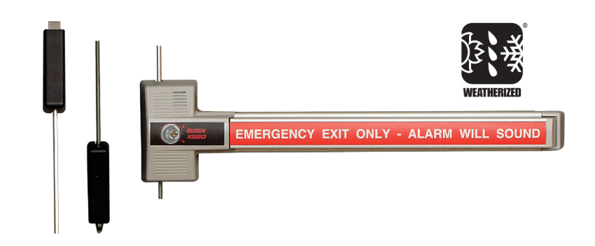
 

Detex ECL Internal Mechanism Parts

The internal mechanism is where most field failures originate on high-cycle ECL installations. The cam bridge converts lever motion into bolt retraction. The bolt assembly is the primary locking element. On installations operating several hundred cycles per day (healthcare corridors, stairwell exits), both wear before other components.


Replacement Mechanism Assembly: ECL-243PH

Detex ECL-243PH replacement mechanism assembly for ECL-230 exit control lock internal components

Detex ECL-243PH replacement mechanism assembly. View product page and order.


The ECL-243PH is the complete internal mechanism replacement for the ECL-230X and ECL-230D. It replaces the cam plate, cam bridge, detent assembly, and actuator components as a single kit. When a field diagnosis determines that multiple internal components have worn simultaneously, or when the failure mode is unclear, replacing the complete mechanism assembly is more cost-effective than sourcing individual components. This is the correct replacement for ECL-230X, ECL-230X-W, ECL-230X-TB, ECL-230X-TDB, and compatible ECL-230D configurations.


Individual Internal Components

When only one component has failed, individual replacement reduces cost and downtime. The most commonly replaced individual components are:

  • ECL-1576-15 cam bridge assembly kit: The bridge that transmits lever depression to the bolt. Fails under high-cycle use when the cam surface wears. Replace when the lever depresses but the bolt does not fully retract.
  • ECL-306-1 bolt assembly: The primary locking bolt. Replace when the bolt sticks in the engaged position or fails to return to the locked position after the delay cycle.
  • ECL-293A detent lever: Holds the bolt in the locked position until the delay cycle completes. Replace when the device fails to hold the 15-second delay and releases immediately on bar depression.
  • ECL-284 detent spring: Return spring for the detent lever. Replace when the detent lever returns sluggishly or not at all.
  • ECL-285A cam plate (bottom): Bottom cam plate in the locking assembly. Replace in conjunction with the cam bridge on multi-component failures.
  • ECL-1576-20 actuator and release lever kit: View the ECL-1576-20 product page. Replaces the actuator and release lever as a paired kit. Replace when the lever operates but the actuator does not engage the release mechanism correctly.
  • ECL-204 switch assembly: View the ECL-204 product page. The electrical switch that triggers the alarm and initiates the delay timer. Replace when the alarm does not sound on bar depression.


Bar, Paddle, and Plate Components

The bar assembly is the highest-wear external component on ECL installations, particularly in applications with repeated unauthorized attempts or high foot traffic. Sixteen bar, paddle, and plate components are stocked across standard, long, and double-door configurations.


Paddle Bar Components

Detex ECL-2109-1 long paddle bar push plate replacement for ECL-230 exit control lock

Detex ECL-2109-1 long paddle bar push plate. View product page and order.

  • ECL-2109-1 long paddle bar push plate: The extended push plate for long-bar ECL configurations. Replace when the push surface is damaged, bent, or when the bar fails to engage the mechanism consistently.
  • ECL-2109 exit bar plate: View the ECL-2109 product page. Standard exit bar plate for ECL-230X base configurations.
  • ECL-2105 long arm bar: Extended arm bar for wide-door or double-door applications.
  • ECL-332 short arm bar: Short arm bar for narrow-door or restricted-clearance applications.
  • ECL-236 bar pin: The pivot pin for the bar assembly. Replace when the bar has excessive lateral play or wobble at the pivot point.


Exit Bar Plates by Language

The ECL-8220 series provides exit bar plates with multilingual "Push Until Alarm Sounds" instructions. Plates are stocked in English (ECL-8220-1), French-Canadian (ECL-8220-7), Spanish (ECL-8220-8), Chinese (ECL-8220-6 and ECL-8220-9). Replace when the instruction text has worn or when a building's occupant language profile requires a change from the installed plate.


Strike Kits and Hardware

Strike selection determines whether the bolt engages the frame correctly on each cycle. Incorrect or worn strikes are a common cause of incomplete bolt engagement on ECL installations.

  • ECL-437K adjustable surface strike: The primary field-adjustable surface strike for ECL-230X and ECL-230D installations. Adjustable to accommodate minor frame misalignment without shimming.
  • ECL-435K adjustable strike bracket: The mounting bracket for the ECL-437K strike. Replace when the bracket is bent or when frame clearance prevents correct strike positioning.
  • ECL-439K mortise strike plate kit for ECL-230D: Mortise-style strike for ECL-230D double-door applications where a surface strike is not appropriate.


Cover, Shield, and Backplate Components

  • ECL-355 cover: The protective cover over the ECL mechanism housing. Replace when damaged or when the cover no longer seats correctly after servicing.
  • ECL-354AR back plate: The back plate that mounts the ECL to the door face. Replace when the back plate is bent or when the mounting holes are damaged.
  • ECL-419 shield: Anti-vandalism shield for the bar and mechanism housing. Install on applications with documented vandalism risk.
  • ECL-405-X cover lock key: The key for the cover lock that prevents unauthorized access to the mechanism housing. Order as the ECL-405-KIT for the complete cover lock key kit.
  • ECL-354AR back plate: Rear mounting plate for ECL body-to-door attachment.


Outside Trim and Cylinder Components

  • ECL-620 outside lever trim: The outside lever handle for ECL installations where outside entry is required. The ECL-620 provides lever-controlled outside entry without compromising the delayed egress function from inside.
  • ECL-1595 standard cylinder collar: The cylinder collar for key cylinder integration. Replace when the collar is damaged or when a cylinder is being replaced on an existing installation.
  • ECL-445K-7 keyed-alike rim cylinder: Seven-pack keyed-alike rim cylinders for installations where multiple ECL devices must be keyed to the same key.


Accessory Kits

  • ECL-2111K siren/battery conversion kit: Converts an existing ECL installation to the current siren/battery configuration. Use when replacing the alarm module or upgrading an older device to current battery specifications.
  • ECL-498K outside pull and warning sign kit: Combines an outside pull handle with a warning sign for applications where outside approach needs to communicate the delayed egress status to incoming users.
  • ECL-475K decorative back plate kit: Trim kit for architectural applications where a finished appearance is required around the ECL body.
  • ECL-2100K bar guard kit: Protective guard for the bar assembly. Install on applications with documented bar damage or vandalism risk.
  • ECL-436K panic bar plate guard kit: Guard kit for the panic bar plate. Protects the push plate instruction text from wear and damage on high-cycle installations.


Delayed Egress Door Signs: Code Requirement, Not Accessory

The ECL-395 series of delayed egress door signs is a code requirement under IBC Section 1010.2.9 and NFPA 101 Section 7.2.1.6. Both codes require that a sign be posted on the door or the adjacent wall at delayed egress devices, informing occupants that the door will open in 15 seconds when the bar is pushed and the alarm is sounding.

Failure to post the required sign is a code violation independent of whether the device itself is functioning correctly. During NFPA 80 annual fire door inspections and local AHJ inspections, missing or damaged delayed egress signs are cited as a deficiency requiring immediate correction. For annual inspection requirements, see the NFPA 80 inspection guide.


Delayed egress signs are stocked in seven language versions:

Part NumberLanguageFormat
ECL-395-1EnglishStandard delayed egress door sign
ECL-395EnglishAlternate format
ECL-395-2 / ECL-395-3French-CanadianTwo format options
ECL-395-4SpanishDelayed egress door sign
ECL-395-6 / ECL-395-7FrenchTwo format options
ECL-395-8 / ECL-395-9GermanTwo format options
ECL-395-10 / ECL-395-11ChineseTwo format options
ECL-395-12 / ECL-395-13English/EuropeanTwo format options


When to Replace vs When to Replace the Complete Device

Most field failures on ECL-230X installations can be resolved with individual or mechanism assembly replacement rather than a full device swap. The decision depends on which components have failed and the age of the installation.

  • Replace individual components when the failure is isolated to a single part (detent spring, bolt assembly, cam bridge, switch assembly) and the device is within its service life.
  • Replace the mechanism assembly (ECL-243PH) when multiple internal components have worn simultaneously or when the failure mode is ambiguous after inspecting individual parts.
  • Replace the complete device when the housing is damaged beyond cosmetic repair, when the device is more than 15 years old with no service history, when the locking configuration needs to change (single-point to 3-point), or when weatherized status is being added to a previously interior-rated installation.

For guidance on OEM versus aftermarket parts compatibility on exit control locks, see the OEM vs aftermarket commercial door hardware guide. For a broader maintenance and inspection schedule, see the commercial door hardware maintenance checklist.


Applications by Building Type

The Detex ECL is most commonly specified in the following building types. Each application has specific configuration requirements that determine which parts are needed:

Building TypeTypical ECL ApplicationConfiguration Note
HealthcareMemory care and behavioral health stairwells, elopement preventionInterior ECL-230X, high-cycle mechanism parts
Government buildingsRestricted stairwell access, utility exitsECL-600 where fire-rated; ECL-445K-7 keyed-alike cylinders
Parking garagesPedestrian exits from parking structure to streetWeatherized ECL-230X-W configurations required
Warehouses and industrialLoading dock personnel exits, restricted accessWeatherized where exposed; bar guard kit for forklift proximity
UniversitiesDormitory secondary exits, restricted building accessECL-8220 exit bar plates in multilingual buildings


Source Detex ECL Parts at Security Parts

Security Parts stocks all 59 Detex ECL parts across the ECL-230X, ECL-230D, ECL-600, and ECL-230X-W families. The catalog includes complete replacement devices, the ECL-243PH mechanism assembly kit, all individual internal components, bar and paddle assemblies, strike kits, delayed egress signs in seven languages, cylinder and trim options, and accessory kits for vandalism protection and alarm conversion.

For the full exit control lock and exit alarm parts catalog, see the exit alarms parts and diagrams guide. For broader exit device parts coverage, see the exit devices parts guide and the commercial exit device parts guide.

For life safety hardware guidance by building type, see the guides for healthcare, government buildings, parking garages, warehouses and industrial, and universities and colleges.

For access control integration with delayed egress devices, see the access control and commercial door hardware integration guide.

Same-day shipping on stocked components. Call 845-935-0301 for pre-order compatibility support on Detex ECL parts before your order is placed.


About the Author

This guide was written by the Security Parts team, a commercial door hardware specialist serving locksmiths, facilities managers, general contractors, and access control integrators since 2001. Security Parts stocks the complete Detex ECL parts catalog across all ECL-230X, ECL-230D, ECL-600, and weatherized configurations, with same-day shipping on stocked components and pre-order compatibility support at 845-935-0301.

Schlage L283 Trim Parts Guide: Lock Cases, Spring Cages, Mounting Plates, and L583 Components

Quick Answer

The Schlage L Series mortise lock uses two separate part families for replacement:

  • L283 covers the outside trim assembly: lock cases (function-specific), spring cages, spindles, mounting plates, rose trim, latchbolts, deadbolts, coin turns, electrified chassis, and VandlGard cases.
  • L583 covers the internal mortise lock body: mounting posts (by door thickness), retractor assembly, hub and spring components, fire door fuse and catch, and internal mechanism parts.
  • Lock cases are function-specific and must match your L9xxx function code exactly. Using the wrong case prevents the lock from operating.
  • VandlGard locks (LV-prefix function codes) need VandlGard-specific L283 cases and are not interchangeable with standard L283 cases.
  • L583 mounting posts must match door thickness exactly, from 1-3/4 inches to 3-1/2 inches. Ordering the wrong length is the most common parts error on L Series installations.
  • L583-748 retractor hub replaces the discontinued L583-019. Two required per lock.

Security Parts stocks all 195 L283 and L583 components. Call 845-935-0301 for pre-order compatibility support. Browse the full Schlage parts catalog or navigate directly to the mortise lock parts catalog.


What L283 and L583 Mean in the Schlage L Series

When ordering replacement parts for a Schlage L Series mortise lock, two part number prefixes appear repeatedly: L283 and L583. Understanding what each covers before searching for a part saves significant time and prevents wrong-part orders.

L283 is the Schlage designator for the outside trim assembly of the L Series. This includes everything that interacts with the user on the exterior of the door: the lock case mechanism that determines how the lever and deadbolt function, the spring cage that returns the lever, the spindle that connects the lever to the lock case, the mounting plate that secures the trim to the door face, the rose trim that covers the escutcheon hole, latchbolts, deadbolts, and coin turns.

L583 is the Schlage designator for the internal mortise lock body components. These are the parts inside the mortise case itself: the mounting posts that hold the trim to the door at the correct thickness, the retractor assembly that drives the latch, the hub and spring components, the fire door fuse and catch required on fire-rated assemblies, and the internal mechanism parts including links, springs, and cams.

When a problem appears at the outside trim level: a lever that does not return, a spring cage that is worn, a rose trim that has been damaged: the replacement comes from the L283 family. When the problem is internal to the mortise case: a latch that does not retract fully, a deadbolt that does not throw, a mechanism that binds: the replacement comes from the L583 family.

For a broader overview of the Schlage L Series mortise lock system, see the Schlage L Series mortise lock parts guide and the Schlage L Series parts and diagrams guide. For function code reference across all L9000 models, see the commercial lock function codes guide.


L283 Lock Cases: Matching the Case to the Function Code

The lock case is the single most important Schlage L283 trim part to order correctly. It determines the mechanical behavior of the lock, whether the lever is always free, key-controlled, thumbturn-controlled, or electrified. Because lock cases are function-specific, the function code stamped on the existing mortise case must be confirmed before ordering a replacement.

Schlage L283-112 basic lock case for L9000 series mortise lock L Series trim parts

Schlage L283-112 basic lock case for the L9000 series. View product page and order.


Standard L283 Mortise Lock Cases

The standard L283 lock case range covers 22 function-specific configurations. Each is matched to one or more L9xxx function codes. The most commonly replaced cases include:

Part NumberCompatible Function CodesLock Function
L283-112L9010 (passage)Passage: lever free at all times
L283-131L9010Passage with inside thumbturn
L283-133L9050, L9060, L9070, L9071Storeroom / office / entrance
L283-062L9044, L9040Classroom / security
L283-039L9076, L9077Communicating / dormitory
L283-126L9056Entrance / vestibule
L283-137L9453Storeroom with dead bolt
L283-138L9456, L9457, L9796Office with dead bolt
L283-310L9458Entrance with dead bolt
L283-139L9460, L9462, L9463, L9464Entrance / exit with dead bolt
L283-140L9465, L9466, L9473Communicating with dead bolt
L283-146L9082, L9082EUEntrance / privacy
L283-141L9412, L9480, L9485, L9486Storeroom / classroom with dead bolt
L283-750L9025Passage with dead bolt

The function code is always the correct starting point for a lock case order. Do not attempt to substitute a case from a nearby function code without confirming compatibility. The internal mechanism geometry is specific to the function, and a mismatched case will not operate the lever and latch correctly.

For the complete list of L Series function codes and their mechanical behaviors, see the commercial lock function codes guide.


VandlGard L283 Lock Cases

VandlGard is the Schlage high-security variant of the L Series, designed to resist forced entry and vandalism at the trim assembly. VandlGard locks use LV-prefix function codes: LV9050, LV9056, LV9076, LV9077, LV9080, LV9082, LV9040, LV9044, LV9453, LV9456, LV9458, LV9460, LV9462, LV9480, LV9482, LV9484, LV9485, LV9486.

VandlGard locks require VandlGard-specific L283 lock cases. These are not interchangeable with standard L283 cases even when the function code base number is the same. A standard L283 case ordered for an LV9082 installation will not fit correctly. Twelve VandlGard L283 lock cases are stocked, covering all current LV-series function code configurations.

If your lock has an LV function code, confirm the VandlGard designation before placing any L283 parts order.


LM9300 Lock Cases

The LM9300 is a Schlage small-case mortise lock within the L Series family. It uses a separate set of L283 lock cases (L283-314, L283-316, L283-614) that are not compatible with standard L Series mortise cases. The LM9300 is frequently specified for interior applications where the full L9000 case size is not required. Three LM9300-specific lock cases are stocked.


L283 Electrified Chassis Parts

Electrified L Series mortise locks use L283 electrified chassis in place of standard lock cases. The chassis integrates the electrical components that allow the lock to respond to access control signals. Twenty-six electrified chassis configurations are stocked, covering the full range of Schlage EL, EU, LV, and LM9300 electrified function combinations.

Electrified chassis are organized by function code group and monitoring option:

  • L9090 and L9092 series: Eight chassis variants covering base, RX (request-to-exit monitoring), LX (latch monitoring), RX+LX combined, and DPS (door position sensor) configurations.
  • L9091, L9093, and L9095 series: Eight chassis variants covering the same RX, LX, and DPS monitoring combinations.
  • L9492 and L9494 series: Four chassis variants for electrified entry functions with RX, LX, and DPS options.
  • L9493 and L9495 series: Four chassis variants for electrified entry with monitoring combinations.
  • LV9090, LV9092 (VandlGard electrified): Two chassis variants for the electrified VandlGard configurations.
  • LV9091, LV9093, LV9095 (VandlGard electrified): Two chassis variants.
  • LM9300 electrified (L9350/L9370/L9180): One RX module chassis, part L283-452.

For guidance on integrating the L Series electrified mortise lock into an access control system, see the access control and commercial door hardware integration guide. For a comparison of electrified mortise locks versus electric strike configurations, see the electrified mortise lock vs electric strike guide.


L283 Trim Components: Spring Cages, Spindles, Mounting Plates, and Rose Trim

Spring Cages: L283-040 and L283-341

Schlage L283-040 spring cage replacement for L Series mortise lock trim assembly

Schlage L283-040 spring cage. View product page and order.


Two spring cage options are stocked for the L Series trim assembly:

  • L283-040 spring cage: The standard spring cage for most L Series trim applications. This is the correct replacement when the lever is failing to return to the neutral position after operation, when the return spring is visibly broken or worn, or when the trim assembly is disassembled for a general overhaul.
  • L283-341 LT springcage: The low-torque version of the spring cage, specified when the installation requires reduced lever operating force. The LT springcage is used on ADA-compliant openings where operating force must stay within the 5-pound maximum requirement, or on any application where lighter lever return is specifically called for in the hardware specification.

The spring cage is one of the highest-turnover L Series trim components on high-cycle openings. On doors that operate several hundred cycles per day, the spring cage typically shows wear before other trim components. Replacing the spring cage during routine maintenance is more cost-effective than waiting for full lever failure.


Spindles and Springs

Six spindle and spring configurations are stocked for the L Series trim. The spindle connects the outside lever to the lock case mechanism. Spindle failure typically presents as a lever that turns freely without operating the latch, or a lever with excessive rotational play.

Spindle configurations include standard through-spindle options (L283-060, L283-061, L283-064) and half-dummy application spindles (L283-065). Two spindle and spring kit configurations (L283-198, L283-199) bundle the spindle with the matching return spring for a complete replacement. The correct spindle depends on the door thickness and trim configuration in the existing installation.


Mounting Plates

Schlage L283-378 outside mounting plate assembly for L Series mortise lock trim

Schlage L283-378 outside mounting plate assembly. View product page and order.


Four mounting plate configurations are stocked:

  • L283-378 outside mounting plate assembly: The primary outside mounting plate for L Series trim. Secures the outside trim to the door face and provides the base for the spindle and rose trim.
  • L283-340 outside mounting plate assembly: Alternate outside mounting plate configuration for specific L Series trim arrangements.
  • L283-031 inside lever mounting plate: The mounting plate for the inside lever assembly. Required when the inside lever is removed or when the inside trim is being refitted.
  • L283-150 mounting plate for inside rose: The mounting plate that carries the inside rose trim. Required when the inside rose is damaged or when the inside trim is being replaced on its own.


Rose Trim and Escutcheons

Four rose trim and escutcheon configurations are stocked for the L Series:

  • L283-121: Rose trim without thumbturn, for lever-only outside trim functions.
  • L283-122: Rose trim with thumbturn, for functions where the inside thumbturn controls the outside lever.
  • L283-123: L escutcheon for 1-3/4-inch doors: the full escutcheon plate for standard commercial door thicknesses.
  • L283-101: L escutcheon thru-bolts, screws, and posts for 1-3/4-inch doors: the complete fastener kit for escutcheon installation.


L283 Latchbolts, Deadbolts, and Coin Turns

Schlage L283-049 latchbolt assembly replacement part for L Series mortise lock

Schlage L283-049 latchbolt assembly. View product page and order.


Latchbolts

The L283-049 latchbolt assembly is the primary latchbolt replacement for the L Series mortise lock. It is the spring-loaded bolt that extends and retracts as the lever is operated and that holds the door in the closed position. The L283-008 and L283-006 auxiliary latchbolt assemblies provide the anti-shim deadlatch function that prevents the latchbolt from being pushed back with a credit card or shim. On ANSI A156.13 compliant mortise locks, the auxiliary latchbolt is a required safety feature.


Deadbolts

Five deadbolt configurations are stocked: L283-075, L283-676, L283-003, L283-004, and L283-099. The correct deadbolt depends on the backset and function of the specific lock. L283-075 is the standard deadbolt for most L Series mortise configurations with a deadlocking function. L283-003 and L283-004 are 2-3/4-inch backset deadbolt options. L283-099 is the small-case mortise deadbolt for L Series locks with the L4606/L4608/L4640/L4660/L4680 and L4096 functions.


Coin Turns

Fourteen coin turn configurations are stocked in seven sizes: 19mm, 23mm, 25mm, 31mm, 37mm, 43mm, and 48mm. Each size is available in two versions: standard (L283-124 series) and Torx-fastener (L283-056 series). The coin turn is the small rotary button on the inside trim that controls the deadbolt or privacy function. Coin turn size is matched to the existing installation. When replacing a coin turn, measure the existing button diameter before ordering.


L583 Mortise Lock Body Parts

Mounting Posts by Door Thickness

Seventeen L583 mounting post configurations are stocked, covering door thicknesses from 1-3/4 inches to 3-1/2 inches. Two mounting post series are available: the L583-200 series (L583-211 through L583-219) and the L583-500 series (L583-497 through L583-504). Both series cover the same door thickness range.

Door ThicknessL583-200 SeriesL583-500 Series
1-3/8"L583-211Not available
1-3/4"L583-212L583-497
2"L583-213L583-498
2-1/4"L583-214L583-499
2-1/2"L583-215L583-500
2-3/4"L583-216L583-501
3"L583-217L583-502
3-1/4"L583-218L583-503
3-1/2"L583-219L583-504

Measure the door thickness before ordering mounting posts. If the posts are too short, the trim will not seat correctly and the lever will have excessive play. If too long, the trim will not pull tight against the door face.


Retractor Assembly Components

The retractor assembly is the internal mechanism that draws the latchbolt back when the lever is operated. Eight L583 retractor components are stocked:

  • L583-748 retractor hub: Replaces the discontinued L583-019. Two required per lock. This is the most commonly replaced retractor component on older L Series installations. If the latch is slow to retract or does not fully engage the retractor, this is the first component to inspect.
  • L583-025 retractor crank: The crank that converts lever rotation into linear latch retraction force.
  • L583-022 retractor rocker: The rocker arm that transfers motion from the retractor crank to the latch.
  • L583-024 retractor link: The connecting link between the retractor rocker and the latch assembly.
  • L583-021 retractor lever: The internal lever that drives the retractor assembly.
  • L583-058 simultaneous retractor: Used on simultaneous retraction functions where both latch and deadbolt retract together.
  • L583-053 simultaneous retractor (alternate): Alternate simultaneous retraction configuration.
  • L583-020 retractor hub spacer: Spacer component within the retractor hub assembly.


Hub and Spring Components

Four hub and spring components handle the rotation of the inside and outside lever mechanisms:

  • L583-029 turn hub: The hub that transmits thumbturn rotation to the deadbolt mechanism.
  • L583-030 entrance hub: The hub for the entrance function that allows the outside lever to operate when the lock is in the unlocked state.
  • L583-035 turn hub spring: The return spring for the turn hub assembly.
  • L583-026 hub spring: The return spring for the entrance hub. Replace when the thumbturn or entrance hub fails to return to its neutral position after operation.


Fire Door Components

Two fire door components are stocked for L Series mortise locks installed on fire-rated door assemblies:

  • L583-027 fire door fuse: A heat-sensitive fusible link inside the mortise case. When exposed to fire temperatures, it releases and allows the door to latch and fully close. Required on all NFPA 80 compliant fire door assemblies using the L Series mortise lock. The fire door fuse must be inspected during annual NFPA 80 inspections and replaced if the fusible link is compromised.
  • L583-027 fire door catch: Holds the latch in the correct position during normal door operation on fire-rated assemblies. Works in conjunction with the fire door fuse to maintain fire door compliance.

For annual NFPA 80 inspection requirements covering fire door hardware including mortise locks, see the NFPA 80 inspection guide and the commercial door fire rating guide.
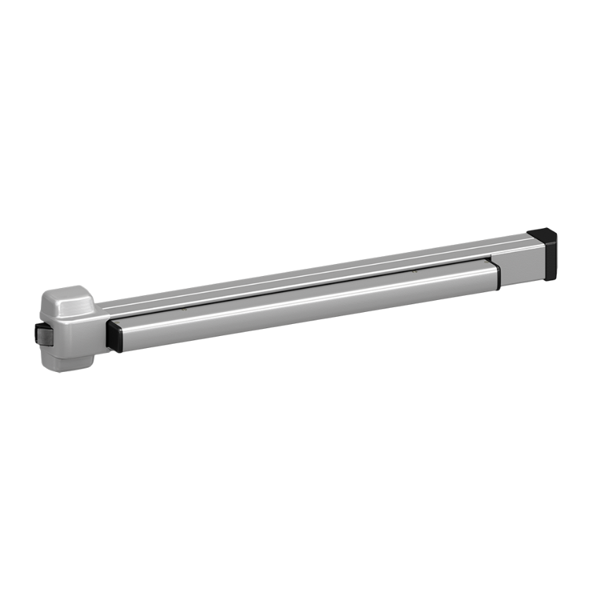
 

Additional Internal Mechanism Parts

The complete L583 internal mechanism parts catalog includes 32 additional components covering the full range of links, springs, pins, cams, catches, and guides that make up the mortise lock body. Key stocked components include:

  • L583-051 transfer lever and L583-156 transfer lifter: Transfer motion from the hub assembly to the retractor in specific function configurations.
  • L583-049 entrance link and L583-048 locking link: Link components within the entrance and locking functions.
  • L583-045 locking catch and L583-047 catch spring: Catch and spring for locking function retention.
  • L583-174 holdback dog and L583-192 dog spring: Holdback components for functions with a holdback or classroom mode.
  • L583-031 cam follower: Follower component within the cam-operated mechanism functions.
  • L583-254 L Series classic standard: The base standard configuration assembly for the L583 mortise lock body.
  • L583-004 standoff post: Standoff post for use with L Series trim configurations requiring additional door face clearance.


How to Identify the Right L283 or L583 Part Before Ordering

  1. Read the function code from the lock body. The function code is stamped or labeled on the mortise lock case: format L9xxx or LVxxx. This code determines which specific L283 lock case applies to the installation.
  2. Confirm standard, VandlGard, or electrified. Standard L Series locks use L283 part numbers. VandlGard versions use LV-prefix function codes and require VandlGard-specific L283 lock cases. Electrified locks need L283 electrified chassis with EL, EU, RX, LX, or DPS designations.
  3. Identify whether the failure is in the trim or the mechanism. Outside trim issues point to L283. Internal mechanism failures point to L583.
  4. Measure door thickness before ordering L583 mounting posts. Posts range from 1-3/8 inches to 3-1/2 inches. The wrong length causes trim misalignment and lever play.
  5. Confirm the correct retractor hub. If the lock was manufactured before the L583-019 was discontinued, the L583-748 is the current replacement. Order two per lock.
  6. Use the Security Parts L Series catalog. Part diagrams on each model page allow visual confirmation of the component before the order is placed.

For the complete Schlage L Series parts and diagrams reference, see the Schlage L Series parts and diagrams guide. For guidance on OEM versus aftermarket compatibility, see the OEM vs aftermarket commercial door hardware guide.


Source Schlage L283 Trim Parts at Security Parts

Security Parts stocks the complete Schlage L283 trim parts and L583 mortise lock body catalog: 109 L283 components and 86 L583 components across all standard, VandlGard, electrified, and LM9300 configurations. The catalog is organized by model with interactive parts diagrams on every model page, allowing visual confirmation of the component before the order is placed.

Browse the Schlage parts catalog or navigate directly to the mortise lock parts catalog. For series-specific reference across all Schlage L Series models and functions, see:

For general mortise lock reference:

Same-day shipping on stocked components. Pre-order part identification and compatibility support at 845-935-0301.


About the Author

This guide was written by the Security Parts team, a commercial door hardware specialist serving locksmiths, facilities managers, general contractors, and access control integrators since 2001. Security Parts stocks the complete Schlage L283 trim parts and L583 mortise lock body catalog across all standard, VandlGard, electrified, and LM9300 configurations, with same-day shipping on stocked components and pre-order compatibility support at 845-935-0301.

LCN 1450 Door Closer Parts Guide: Arms, Tracks, Cylinders, and Covers

Quick Answer

The LCN 1450 is a parallel arm surface door closer available in two configurations: the standard 1450 (arm-and-shoe system) and the 1450T (track arm system). Replacement parts are not interchangeable between the two. Here is what to know before ordering:

  • 1450 arms: Six types: regular (3077/62A), EDA extra duty (3077EDA), spring cushion (3077CNS/3077SCNS), PA parallel arm (3077PA), and long arm (3077L). Hold-open variants use 3049 in place of 3077.
  • 1450T tracks: Four options: 3038 standard, 3038H hold-open, 3038B bumper, 3038HB both. Track roller (3034H) and hold-open clip (3054) are the highest-wear components.
  • PA shoe (62PA) is handed : specify Left or Right when ordering. (Remove em dash replacement below) specify Left or Right when ordering. The 62A auxiliary shoe is not handed.
  • Spring cush block (3080) is replaceable without replacing the full arm.
  • Cylinders: 3071 standard, 3071DEL delay action.

Security Parts carries the complete LCN 1450 parts catalog with same-day shipping on stocked items. Call 845-935-0301 for pre-order part identification support. Browse the full LCN parts catalog or navigate directly to the LCN 1450 model page.


What the LCN 1450 Is and Where It Is Installed

LCN 1450 door closer parts guide model overview parallel arm surface closer

LCN 1450 parallel arm door closer. View model page and parts diagrams.


The LCN 1450 is a parallel arm surface door closer designed for applications where a standard arm swing would create a clearance problem. On a standard door closer, the arm sweeps outward as the door opens. On an aluminum storefront, a narrow corridor, or a door swinging into a stairwell, that arm arc can strike a wall, trim, or obstruction. The parallel arm geometry on the 1450 keeps the arm close to the door face throughout the swing, eliminating the clearance issue.

The 1450T variant uses a track arm system instead of a conventional arm-and-shoe setup. The track arm's roller travels inside a channel mounted on the door face, providing a smooth, linear closing force that many specifiers prefer on high-cycle aluminum storefront doors. The 1450 and 1450T share the same closer body but use entirely different arm and track hardware. Parts do not interchange between the two configurations.

For a broader reference on LCN door closer selection by application, see the LCN commercial door closer selection guide and the commercial door closers types guide. For sizing requirements, see the LCN door closer sizing guide.


LCN 1450 Arm System: All Types Explained

The arm system is the most frequently replaced component group on the LCN 1450. Arm selection determines the mounting geometry, the closing force distribution, and whether hold-open function is included. Every arm type is available in a standard (non-hold-open) version and a hold-open version.

The part number convention is straightforward: 3077 = standard arm (no hold-open), 3049 = hold-open arm. Add the arm type suffix and the result is the complete arm part number.


Regular Arm: 1450-307762A and 1450-304962A

The regular arm is the baseline configuration for the 1450 when the application requires a parallel arm geometry without any special closing characteristics. It pairs with the 62A auxiliary shoe. The 62A shoe is not handed and fits either side of the installation. The hold-open version is designated 1450-304962A.

LCN 1450-3077EDA extra duty arm replacement part for 1450 door closer

LCN 1450-3077EDA extra duty arm. View product page and order.


Extra Duty Arm: 1450-3077EDA and 1450-3049EDA

The EDA (extra duty arm) is a heavier-gauge arm specified for high-cycle openings, institutional applications, or any door that receives heavier-than-normal traffic. It uses the same 62A shoe as the regular arm but is built to a higher structural tolerance. On openings where regular arms are showing premature wear or bending, the EDA is the correct replacement choice. The hold-open EDA is the 1450-3049EDA.

EDA versions with the 62G shoe are also available: 1450-3077EDAG and 1450-3049EDAG.


Spring Cushion Arm: 1450-3077CNS, 1450-3077SCNS, and Hold-Open Variants

The spring cushion arm incorporates a spring cush block (3080) within the arm assembly. The spring cushion function absorbs the initial closing force, providing a gentler door pull at the beginning of the closing cycle. This is specified on doors where a hard initial pull is a problem, such as glass doors where rapid closing can cause frame stress or where ADA opening force requirements are being approached.

The 3077CNS is the standard spring cushion arm. The 3077SCNS adds a spring within the cush block for a stronger cushion effect. Hold-open versions are the 1450-3049CNS and 1450-3049SCNS respectively.

The spring cush block (1450-3080) is a replaceable component. If the cushion function has degraded but the arm structure is intact, replacing the 3080 block restores the spring cushion without requiring a full arm replacement.


PA Parallel Arm: 1450-3077PA and 1450-3049PA

The PA arm pairs with the 62PA parallel arm shoe rather than the standard 62A auxiliary shoe. The 62PA shoe is handed and must be specified as Left or Right when ordering. Confirm the handing of the existing installation before placing the order: Left is correct when the hinge is on the left side facing the pull side of the door, Right when the hinge is on the right side.

The hold-open version is the 1450-3049PA. Browse the 1450-3077PA parallel arm with 62PA shoe on the product page.


Long Arm: 1450-3077L and 1450-3049L

The long arm provides additional reach where the standard arm geometry does not produce the correct geometry relative to the door width and frame dimensions. It uses the 62A shoe and follows the same hold-open designation pattern: 1450-3049L for the hold-open version.


LCN 1450T Track System: Tracks, Rollers, and Clips

LCN 1450T-3038 standard track replacement part for 1450T door closer

LCN 1450T-3038 standard track. View product page and order.


The 1450T track system uses a single arm type (the 1450T-3077T standard arm) paired with a track assembly selected to match the required closing function. The track roller and hold-open clip are the components most subject to wear on high-cycle 1450T installations.


Track Variants: Standard, Hold-Open, Bumper, and Combined

Part NumberTrack TypeHold-OpenBumperPrimary Application
1450T-3038StandardNoNoStandard commercial, no hold-open needed
1450T-3038HHold-openYesNoOpenings requiring door to hold at 80-110 degrees
1450T-3038BBumperNoYesProtects wall or stop at full swing position
1450T-3038HBHold-open + bumperYesYesHigh-traffic, hold-open with wall protection


Wear Components: Track Roller and Hold-Open Clip

On high-cycle 1450T installations, the track roller (1450T-3034H) and hold-open clip (1450T-3054) are the first components to show wear. The track roller develops flat spots after extended cycling. The hold-open clip loses tension and fails to hold the door at the correct position. Both are replaceable without removing the closer body from the door. These components should be inspected during any scheduled maintenance visit on a 1450T installation. For a full maintenance schedule reference, see the commercial door hardware maintenance checklist.


LCN 1450 Cylinder Assemblies

LCN 1450-3071 cylinder assembly replacement part for 1450 door closer

LCN 1450-3071 cylinder assembly. View product page and order.


Two cylinder assemblies are available for the LCN 1450 and 1450T series.

Standard Cylinder: 1450-3071 and 1450T-3071

The 1450-3071 is the standard cylinder assembly for the 1450 closer body. The 1450T-3071 is the corresponding standard cylinder for the 1450T track arm variant. Both provide conventional spring-tension closing without any delayed action function. The 1450-3071 cylinder assembly is available with same-day shipping when stocked.


Delay Action Cylinder: 1450-3071DEL

The delay action cylinder holds the door at its fully open position for an adjustable interval before the closer spring begins pulling the door shut. It is specified on high-traffic openings where users need time to pass through without manually holding the door.

Common applications include loading dock entries, accessible entrances where users need extra time to clear the doorway, and healthcare corridor doors where staff frequently pass through carrying equipment. The delay interval is field-adjustable.

The 3071DEL replaces the standard 3071 cylinder directly. No other hardware changes are required when upgrading from a standard cylinder to a delay action cylinder.


Covers, Mounting Plates, and Accessory Components

Cover Options for the LCN 1450

Four cover options are available:

Part NumberCover TypeBest For
1450-72Standard slim coverMost commercial applications, clean profile
1450-72FCFull plastic coverModerate-duty protection, economy option
1450-72MCFull metal coverInstitutional, high-abuse, heavy-duty applications
1450-72ALTAlternate coverNon-standard profile or replacement fit requirements


Mounting Plates

The mounting plate connects the closer body to the door face. Four mounting plate options are available:

  • 1450-18: Standard mounting plate, most common configuration.
  • 1450-18FC: Standard mounting plate for use with full cover installation.
  • 1450-18PA: PA mounting plate for parallel arm installations.
  • 1450-18PAFC: PA mounting plate configured for use with the full cover.

Select the mounting plate that matches both the arm configuration (standard vs PA) and whether a full cover is being installed. The cover type determines which plate variant applies.


Additional Accessory Parts

Several additional components are stocked for the LCN 1450 series:

  • 1450-3080 spring cush block: Replacement cush block within the CUSH arm assembly. Replaceable without full arm disassembly. The spring cush block is the correct first replacement on any CUSH arm showing degraded cushion performance before the full arm is condemned.
  • 1450-146 pinion cap: Cap at the pinion end of the closer body. Replace if cracked, missing, or showing fluid seepage around the pinion end.
  • 1450-30 cush shoe support: Support component within the spring cushion arm assembly. Inspect when the CUSH arm shows lateral instability.
  • 1450-61 blade stop spacer: Spacer component for blade stop configurations. Required for correct stop positioning on blade stop mount applications.
  • 1450-419 flush panel adapter: Adapter for flush panel mounting applications where the door surface does not accommodate standard mounting geometry.
  • 1450-31 cover screw: Replacement cover mounting screw. Rebox kits (1450-Rebox-Kit and 1450T-Rebox-Kit) include replacement boxes and instruction sheets for models that have lost their original documentation.


How to Identify the Right LCN 1450 Part

The fastest identification path starts with the model label on the closer body, which confirms whether the closer is a 1450 or 1450T. From there, the arm or track currently installed determines which replacement parts apply.

  1. Confirm 1450 vs 1450T. Check the model label on the body. If a track channel is present on the door face and the arm runs into it, the closer is a 1450T. If a conventional arm connects to a shoe on the door frame, it is a standard 1450.
  2. Identify the arm type. On the 1450: look at the arm geometry and any markings on the arm body. The EDA arm has a heavier cross-section than the regular arm. The CUSH arm has a visible spring block at the body connection point. The PA arm attaches directly to the door face without a frame shoe. On the 1450T, the arm type is always 1450T-3077T; the variable is the track assembly.
  3. Check the shoe. If a 62A shoe is installed, the arm is a regular, EDA, or long arm. If a 62PA shoe is installed, the arm is a PA configuration. Note the handing before ordering the 62PA.
  4. Match the track (1450T only). Inspect the track channel. A notch or detent near the open position indicates a hold-open track (3038H or 3038HB). A bumper pad at the end of the channel indicates a bumper track (3038B or 3038HB). No notch or bumper: standard 3038 track.
  5. Order by part number. Use the component number from the LCN 1450 model page parts diagram to confirm the exact part number before ordering.

For help interpreting parts diagrams, see the door closer parts diagram guide. For questions about whether a component is OEM or aftermarket compatible, see the OEM vs aftermarket guide.


Source LCN 1450 Door Closer Parts at Security Parts

Security Parts carries the complete LCN 1450 parts catalog, including all arm types, the full 1450T track system, cylinders, covers, mounting plates, and accessory components. Browse the door closers parts catalog or navigate directly to the LCN 1450 model page for interactive parts diagrams organized by component.

For coverage of the full LCN door closer parts catalog across all series:

For installation and adjustment references, see the how to install a commercial door closer guide and the how to adjust a commercial door closer guide. For fire door compliance requirements relevant to closer selection, see the commercial door fire rating guide. For ANSI/BHMA grade requirements, see the ANSI/BHMA door hardware standards guide.
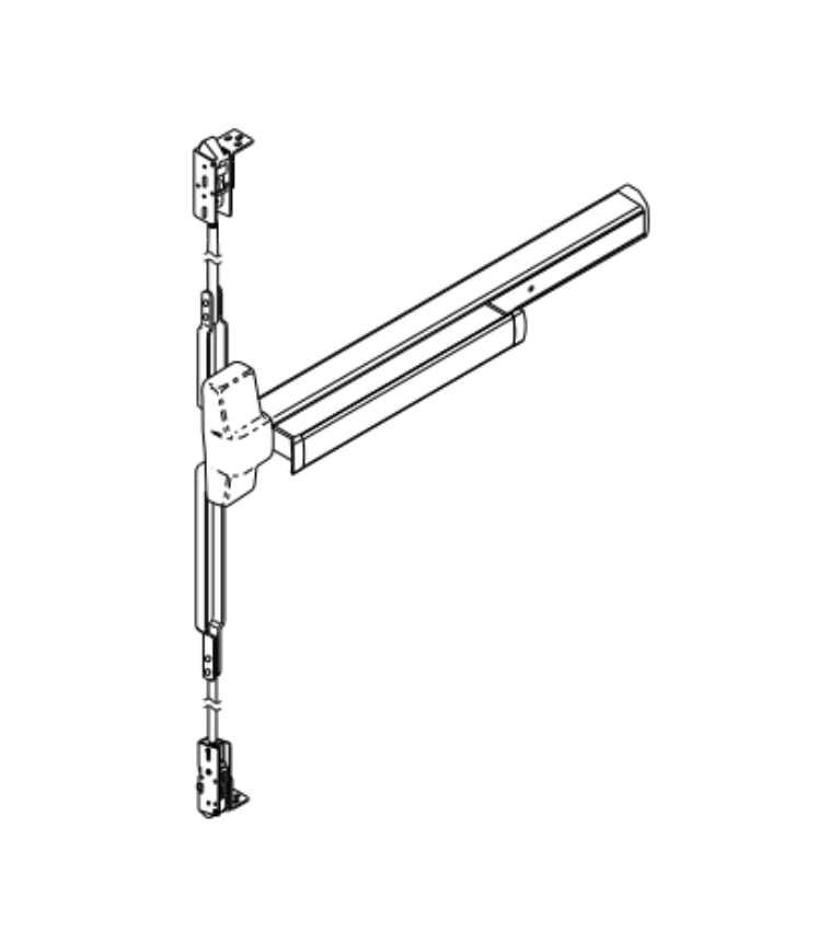
Same-day shipping is available on stocked components. Pre-order part identification support is available at 845-935-0301. For repair and replacement guidance beyond parts identification, see the commercial door hardware replacement and repair guide.


About the Author

This guide was written by the Security Parts team, a commercial door hardware specialist serving locksmiths, facilities managers, general contractors, and access control integrators since 2001. Security Parts carries the complete LCN 1450 door closer parts catalog across all arm, track, cylinder, and cover configurations, with same-day shipping on stocked components and pre-order part identification support at 845-935-0301.

How to Install an Electric Strike: Frame Prep, Wiring, and Alignment

Quick Answer

Installing an electric strike correctly comes down to four decisions made in the right order: mode first, voltage second, frame prep third, wiring fourth. Here is the short version:

  • Choose fail-safe or fail-secure before ordering. Fire-rated assemblies require fail-secure. This determines your power supply type and fire compliance path.
  • Verify voltage before connecting anything. Use a multimeter at the power supply output. Exceeding rated voltage by 10 percent damages the solenoid permanently.
  • Fire-rated frames require factory cutouts. Field-cutting a fire-rated frame voids the fire label. Specify the electric strike prep when you order the frame, not after it arrives.
  • Install the back EMF suppression diode. It protects the access control panel from voltage spikes every time the solenoid de-energizes.

Security Parts carries the full Von Duprin electric strike catalog for the 5100 Series, 6100 Series, and 6300 Series with same-day shipping on stocked components. Call 845-935-0301 for pre-installation compatibility support. For a broader reference on commercial door hardware selection, see the commercial security hardware guide.


Before You Touch the Frame: The Two Decisions That Come First

Most electric strike installation problems trace back to a decision made too late in the process. Frame cutouts, power supply specifications, and fire compliance paths all depend on two choices that need to happen before the frame is ordered and before a multimeter is picked up.


Decision 1: Fail-Safe or Fail-Secure?

Von Duprin 5100 Series electric strike installation fail-safe fail-secure field selectable commercial door

Von Duprin 5100 Series electric strikes. Browse 5100 Series models.


Fail-secure means the strike stays locked when power is cut. Fail-safe means it releases. This is the most consequential decision in the installation because it determines the power supply type, the fire rating eligibility, and the NEC compliance path.

Use fail-secure when:

  • The door is on a fire-rated assembly. Fire doors must positively latch during a power outage. Fail-safe operation on a fire door fails this requirement.
  • The door is a secured perimeter entry that must remain locked if the access control system loses power.
  • The local Authority Having Jurisdiction (AHJ) has not specifically approved fail-safe for the application.

Use fail-safe when:

  • The door is on a non-fire-rated egress path where free egress during a power outage is required by code.
  • The application is a stairwell or emergency egress corridor that must remain accessible if the system fails.
  • The access control specification explicitly calls for fail-safe and the AHJ has approved it.

Most Von Duprin 5100 and 6100 Series electric strikes ship from the factory in fail-secure mode. Field reversal to fail-safe is available on select models. For a detailed comparison of how fail-safe and fail-secure interact with fire door hardware, see the electric strikes complete guide and the commercial door fire rating guide.
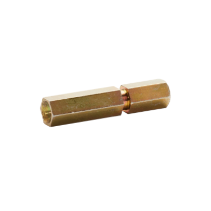
 

Decision 2: What Voltage Does the Strike Require?

Most commercial electric strikes operate on 12VDC, 24VDC, or both. Some models accept AC voltage with an external rectifier. Confirm the voltage requirement of the specific strike model before specifying the power supply. The power supply must be sized for both the inrush current (higher, momentary) and the holding current (lower, continuous) of the strike, not just the holding current shown in most marketing specs.

Voltage mismatch is the single most common cause of solenoid failure in the field. Do not rely on a power supply's label alone. Verify actual output voltage with a multimeter before connecting the strike.


Frame Preparation: Requirements by Door and Frame Type

An electric strike requires a larger frame cutout than a standard strike plate. The cutout dimensions vary by strike model and faceplate selection. The frame must also include a wire access point for routing low-voltage wiring from the back of the frame cavity to the strike location.


Hollow Metal Frames

Hollow metal frames are the most common installation type for commercial electric strikes. The standard process:

  1. Mark the strike centerline based on the latchbolt height when the door is closed.
  2. Use the cutout template included with the strike to mark the frame cutout dimensions.
  3. Cut the frame using an appropriate metal cutting tool. Verify the cut is clean and burr-free before mounting.
  4. If the frame does not have factory-installed mounting tabs, install the no-weld mounting tab kit before inserting the strike body.
  5. Confirm a wire access point exists in the frame. If not, add a wire access hole in the back of the frame channel before the strike is inserted.


Fire-Rated Frames: Factory Prep Is Mandatory

This is the most frequently violated rule in electric strike installation. The electric strike cutout in a fire-rated frame must be factory-prepared as part of the original frame fabrication order. Field-cutting a fire-rated frame voids the UL fire label on the frame, which voids the fire rating of the entire door assembly.

The factory prep requirement means the electric strike model must be selected and specified before the frame is ordered. At minimum, specify:

  • The strike model and faceplate option (which determines the cutout dimensions)
  • The wire access point location
  • The conduit knockout or channel pathway for routing low-voltage wiring

For compliance requirements on fire door assembly hardware, see the commercial door fire rating guide, the NFPA 80 inspection guide, and the ANSI/BHMA door hardware standards guide.
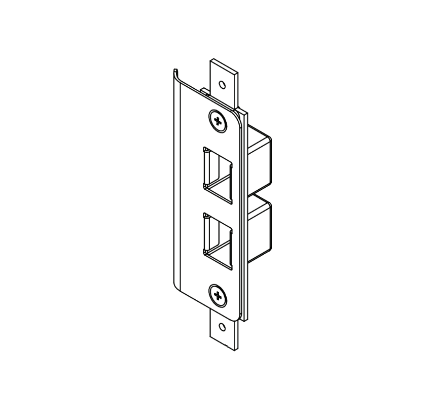
 

Wood Door Frames

Electric strikes in wood door frames use wood screws instead of mounting tabs. The frame cutout follows the same template as hollow metal, but wood frames do not require a factory prep for fire-rated applications because rated wood frames use different construction and listing requirements. Confirm fire rating status of the specific wood frame before proceeding without factory prep.


Aluminum Storefront Frames

Aluminum storefront frames require a no-weld mounting bracket kit. Standard hollow metal mounting tabs cannot be welded to aluminum. The no-weld bracket system uses adhesive shims and mechanical fasteners to secure the strike in the aluminum frame cutout. Confirm the strike model is compatible with aluminum frame installation before ordering.


Wiring the Electric Strike: Voltage, Wire Gauge, and Power Connection

Von Duprin 050034 solenoid kit 12VDC 24VDC for 5100 Series electric strike wiring installation

Von Duprin 050034 solenoid kit for 5100 Series. View product page.


Step 1: Verify Voltage at the Source Before Connecting

Before connecting any wiring to the electric strike, use a multimeter to measure actual output voltage at the power supply terminals. Power supplies and low-voltage transformers frequently operate above their stated rating. Any input voltage exceeding the strike's rated voltage by more than 10 percent permanently damages the solenoid coil. This damage is not covered under warranty and is not visible until the solenoid fails under load.


Step 2: Select the Correct Pigtail Connector for the Voltage

Von Duprin 5100 and 6100 Series strikes ship with two pigtail connectors: one marked "12 VDC" and one marked "24 VDC." Connect the pigtail that matches your power supply output, not the strike's rated voltage range.

  • For 12VAC, 12VDC, or 16VAC: use the pigtail marked 12 VDC
  • For 24VAC or 24VDC: use the pigtail marked 24 VDC

Using the wrong pigtail with the correct voltage causes the solenoid to operate outside its optimized current range. Over time, this shortens solenoid life even if the strike appears to function normally.


Step 3: Wire Gauge Requirements by Run Length

Wire gauge requirements vary by run length from the power supply to the strike location. Undersized wire causes voltage drop that reduces the strike's holding force and can cause intermittent release failures.

Run Length12VDC Minimum Gauge24VDC Minimum Gauge
Up to 200 feet18 AWG20 AWG
200 to 300 feet16 AWG18 AWG
300 to 400 feet14 AWG16 AWG

All electric strike wiring installation must comply with NFPA 70 (National Electrical Code). Maintain required separation between low-voltage access control wiring and high-voltage electrical circuits. Terminate all connections inside the frame cavity or junction box, not in the wall cavity where connections cannot be accessed later.


Step 4: AC Power and the Rectifier Requirement

An electric strike connected to an AC power supply without a rectifier will buzz continuously. AC alternates direction at 60Hz, causing the solenoid to cycle at that frequency. The buzzing is not just a nuisance: it accelerates solenoid wear and is audible to occupants.

Install an AC rectifier between the AC transformer and the strike whenever the power source is AC. The rectifier converts AC to DC at the strike, eliminating the buzzing. For wiring diagrams covering the AC rectifier connection and latchbolt monitor wiring, see the electric strike schematic diagram guide.
 

Step 5: Install the Back EMF Suppression Diode

When the electric strike solenoid de-energizes (when power is cut to release or lock the strike), it generates a voltage spike called back EMF. This spike travels back through the wiring to the access control panel's output relay and degrades the relay contacts over time, eventually causing intermittent failures in the access control system.

Install a back EMF suppression diode across the strike terminals, observing polarity (cathode toward the positive terminal on DC-powered models). For AC-powered strikes, use a metal oxide varistor (MOV) instead of a diode. MOVs are not polarity sensitive. Some Von Duprin strike models include the suppression component. If not included, it is available as an accessory in the parts catalog.

For a full reference on access control wiring and signal protection, see the access control integration guide.
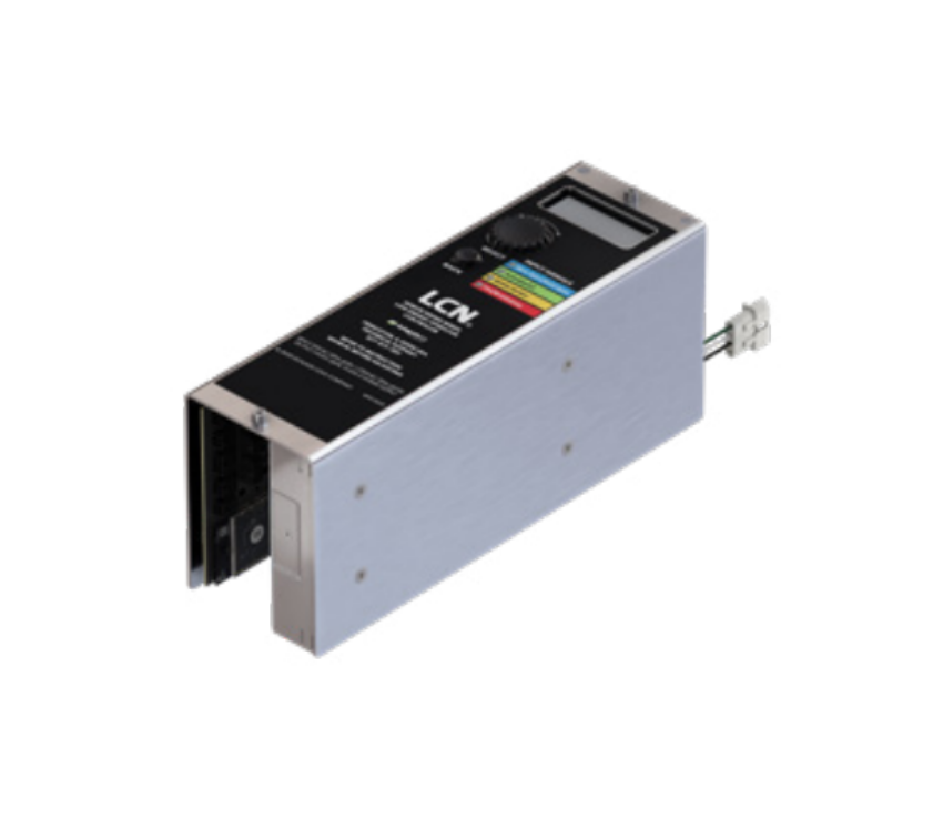
 

Installing the Strike in the Frame

Von Duprin PKGMTG1004 mounting package for 5100 Series electric strike installation

Von Duprin PKGMTG1004 mounting package for 5100 Series. View product page.


Select the Correct Faceplate First

The faceplate is not a cosmetic choice. It determines which lock type the strike is compatible with (cylindrical, mortise, or exit device) and which frame cutout template applies. Selecting the wrong faceplate produces a strike that physically fits the frame but does not properly engage the latch, which causes release failures and return damage.

Von Duprin 5100 and 6100 Series faceplate options cover:

  • Standard cylindrical latchbolts
  • Mortise latchbolts with and without deadlatches
  • Exit device latches (narrow and wide configurations)
  • Hookbolt configurations for non-latchbolt applications

Select the faceplate based on the latch type and backset of the lock installed on the door. For parts reference by strike model, see the electric strike parts guide.
 

Route Wiring Before Inserting the Strike

Route all wiring through the frame channel and leave a sufficient service loop at the strike location before the strike body goes into the frame. Once the strike is mounted, access to the wiring connection point is limited. Pinched wiring between the strike body and the frame is a common installation defect that causes intermittent failures weeks after installation.


Mount the Strike and Confirm Alignment

  1. Insert the strike body into the frame cutout with all wiring routed clear of the strike housing.
  2. Secure using the mounting tabs and provided screws. On hollow metal frames with factory-installed tabs, thread the screws into the tabs finger-tight first.
  3. Close the door and verify the latchbolt enters the keeper cleanly without resistance. Resistance indicates a misaligned centerline.
  4. Tighten the mounting screws fully once alignment is confirmed.


Post-Installation Alignment Adjustments

Horizontal Alignment

If the latchbolt binds or does not retract cleanly when the strike is energized, horizontal alignment is the first adjustment to make. Loosen the mounting screws slightly, shift the strike body horizontally behind the faceplate until latch engagement and release are smooth, then retighten. Most Von Duprin 5100 and 6100 Series strikes allow approximately 1/8-inch horizontal adjustment within the faceplate slot.

For excessive horizontal issues where the 1/8-inch adjustment is not sufficient, remove the shim filler bar from the keeper. This increases the keeper travel range to compensate for larger frame or door alignment problems.


Vertical Alignment (For Strikes With Internal Ramps)

The internal ramps in Von Duprin 6100 Series strikes must be aligned so the deadlatch passes between the two ramps without contacting either ramp. If the deadlatch contacts a ramp, the door will not latch properly when the strike is in the locked state.

  1. Mark the centerline of the deadlatch on the strike faceplate with the door closed.
  2. Remove the strike from the frame.
  3. Loosen the internal ramp screws and slide the ramp assembly until the groove between the ramps aligns with the mark.
  4. Retighten all screws, reinstall the strike, and verify alignment by closing the door.


Testing the Electric Strike After Installation

Von Duprin 6100 Series electric strike installation testing 12VDC 24VDC commercial door

Von Duprin 6100 Series electric strikes. Browse 6100 Series models.


Every electric strike installation requires testing in both the powered and unpowered states before the door is commissioned. Do not skip the unpowered test, especially on fire-rated assemblies.


Powered State Test

  • Apply power to the strike at the rated voltage.
  • Send an unlock signal from the access control panel or apply power directly to the strike terminals.
  • Confirm the keeper retracts and the latchbolt releases cleanly when the door is pulled.
  • Confirm the keeper returns to the locked position after the door closes and the latch re-engages.


Unpowered State Test (Fail-Secure or Fail-Safe Verification)

  • Fail-secure: Disconnect power to the strike. The door should remain locked. Confirm the latchbolt cannot retract manually when the strike is unpowered.
  • Fail-safe: Disconnect power to the strike. The door should open freely. Confirm there is no resistance on the latchbolt retraction.


Fire-Rated Assembly Final Check

On fire-rated door assemblies, perform one final check in both power states: release the door from the open position and confirm it self-closes and positively latches every time. The door must latch without manual assistance in both the powered and unpowered states. If the door fails to latch in either state, the assembly is not compliant and must be adjusted before sign-off.

For ongoing maintenance requirements after installation, including NFPA 80 annual inspection procedures, see the commercial door hardware maintenance checklist.


Common Electric Strike Installation Problems and Fixes

ProblemLikely CauseFix
Strike will not releaseNo power at the strike terminals; wrong pigtail connectorVerify voltage at strike terminals with multimeter; confirm correct pigtail is connected
Strike buzzing continuouslyAC power supply connected without rectifier; incorrect polarity on DC modelInstall AC rectifier; verify polarity if DC-powered
Latchbolt does not fully engage when lockedHorizontal misalignment; backpressure from door bindingAdjust horizontal alignment; check door-to-frame gap (minimum 1/8 inch)
Solenoid has burnt smell after installationIncorrect voltage; wrong pigtail connector for voltageReplace solenoid; verify power supply voltage output with multimeter before reconnecting
Access control panel intermittent failuresNo back EMF diode installed; relay contact degradationInstall suppression diode or MOV across strike terminals
Door fails to latch when strike is lockedVertical misalignment; deadlatch contacting internal rampRealign internal ramps using deadlatch centerline mark procedure


Sourcing Von Duprin Electric Strike Parts at Security Parts

Security Parts stocks the complete Von Duprin electric strike catalog for the 5100, 6100, and 6300 Series, including replacement solenoids, faceplate options, mounting packages, and accessory kits. Browse the complete electric strikes catalog or by series:

For access control integration design including REX switch placement, door position switch wiring, and latchbolt monitor connections, see the access control integration guide. For the choice between an electric strike and an electrified mortise lock for a specific opening, see the electrified mortise lock vs electric strike guide.
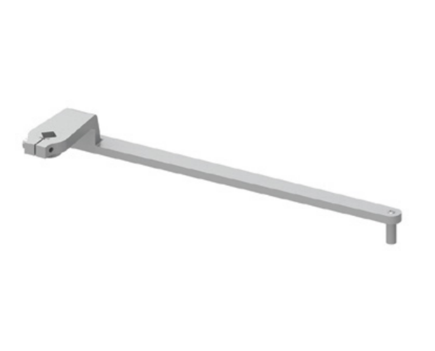
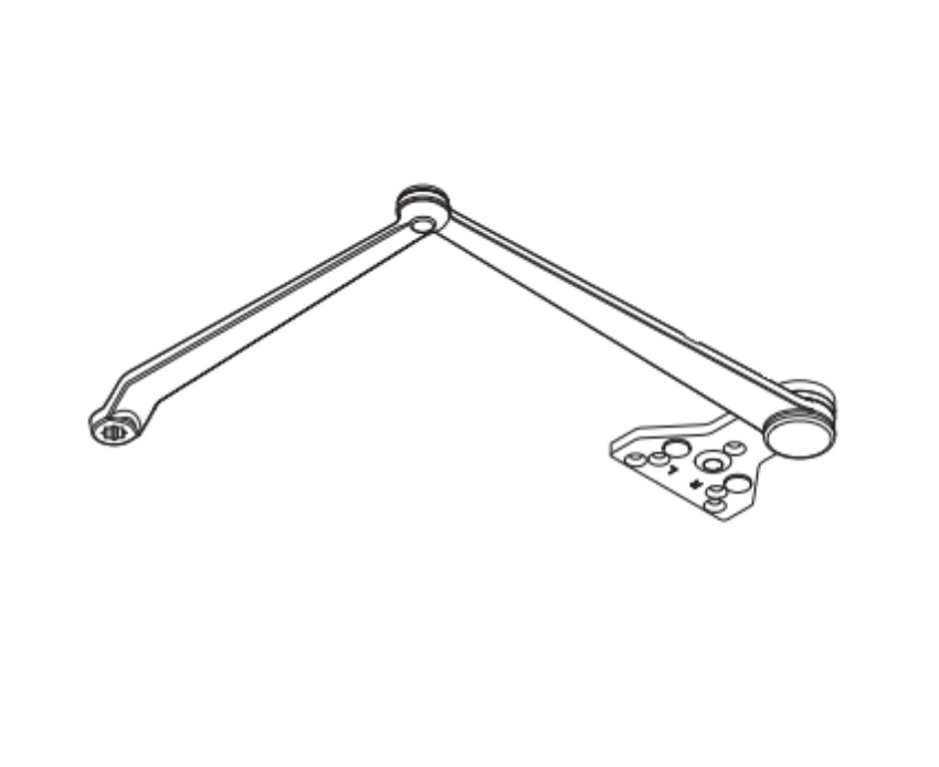
Same-day shipping is available on stocked components. Pre-installation compatibility support is available at 845-935-0301. For a parallel guide on mechanical door hardware installation, see how to install a commercial door closer.
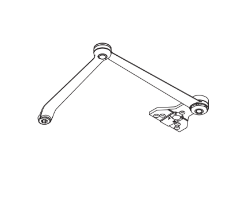
 

About the Author

This guide was written by the Security Parts team, a commercial door hardware specialist serving locksmiths, facilities managers, general contractors, and access control integrators since 2001. Security Parts stocks the complete Von Duprin electric strike catalog for the 5100, 6100, and 6300 Series with same-day shipping on stocked components and pre-installation support at 845-935-0301.

Blog|Security Parts

Blog|Security Parts

Blog|Security Parts