RSS

Blog

Exit Device vs Panic Bar: What Is the Difference and Which One Do You Need

Quick Answer

In everyday commercial door hardware practice, "exit device," "panic bar," and "panic hardware" are commonly used to refer to the same category of hardware. These are door-mounted assemblies with a horizontal push element that releases a latch when pressed, allowing fast single-motion egress. The terms originate from different codes and professional contexts, which is why buyers encounter all three in specifications, purchase orders, and field conversations.

That said, terminology matters in two specific situations: when comparing standard panic hardware to fire exit hardware on a fire-rated door assembly, and when reading code requirements that use one term but not another. This guide explains how the terms are used in practice, where the important distinctions lie, and how to confirm which device type applies to your opening.


Where the Terms Come From

The three terms most buyers encounter are "panic hardware," "exit device," and "panic bar." Each comes from a different context.

"Panic hardware" is the term used in NFPA 101, the Life Safety Code. NFPA 101 defines panic hardware as a latching device that allows the door to open from the egress side by applying force to a bar or panel extending at least half the door width, not requiring the use of a key, special knowledge, or effort to operate.

"Exit device" is the term used in the International Building Code (IBC). The IBC references exit devices in its egress requirements, describing devices that allow doors to be opened from the egress side without a key, special tool, or prior knowledge.

"Panic bar" is an informal industry shorthand that refers to the horizontal push bar or crossbar that is the most visible component of the device. In field use, "panic bar" is widely used to refer to the complete exit device assembly, not just the bar component. You will encounter all three terms used interchangeably in specifications, purchase orders, and product catalogs.

For most commercial door hardware decisions, the key understanding is this: whether the project documents say "panic hardware" or "exit device," they are generally describing the same product category. The applicable code for your jurisdiction and the fire rating status of the door determine the specific device requirements.


What Is an Exit Device
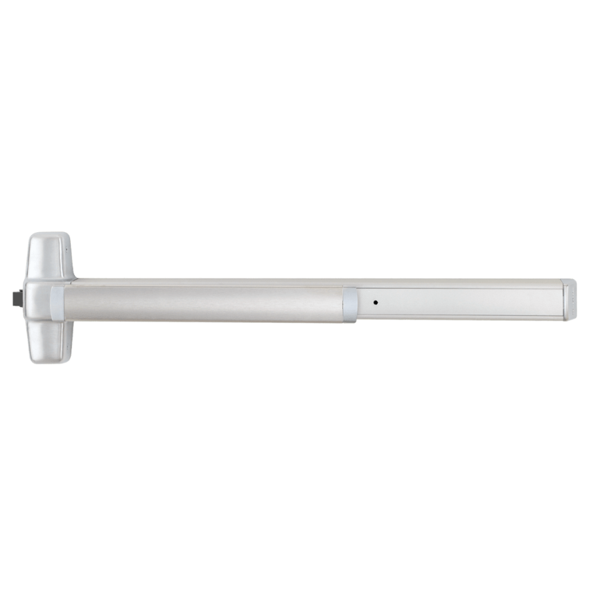
Von Duprin 98/99EO Rim Exit Device -- standard panic hardware for commercial egress doors, exit-only configuration

Von Duprin 98/99EO Rim Exit Device, Exit Only. A standard panic hardware device for non-fire-rated commercial egress doors. View product page.


An exit device is a complete door hardware assembly designed to allow fast, one-motion egress from a building or area. The device is mounted on the door and consists of a push element (bar, crossbar, or touch pad), an internal latch mechanism, and a chassis that transmits the push motion to the latch. When a person presses the bar, the latch retracts and the door opens. No key, prior knowledge, or special effort is required.

Exit devices are used on commercial egress doors in office buildings, schools, healthcare facilities, retail spaces, government buildings, and any other occupancy type where egress hardware is required to meet life safety codes. The device category includes rim exit devices, surface vertical rod (SVR) devices, concealed vertical rod (CVR) devices, and mortise exit devices. Each type suits different door construction and frame conditions.

For a full explanation of exit device parts and component categories, see the exit devices parts guide and the commercial exit device parts guide.


What Is a Panic Bar

A panic bar is a common informal name for the horizontal bar or crossbar element that extends across the door on an exit device. When someone says "panic bar," they may mean the complete exit device assembly, or they may specifically mean the push bar component that the occupant presses to open the door.

In product catalogs, the push bar is listed as a component: for example, a push bar assembly for a narrow stile exit device is a separate orderable part that replaces the bar element while keeping the existing chassis and mechanism in place. In field conversation and specifications, "panic bar" almost always refers to the complete exit device assembly.

The push element of an exit device is not always a bar. Some devices use a touchpad or push pad rather than a full crossbar. Regardless of push element style, the device functions on the same principle: one-motion egress without a key.


Exit Device Types by Mounting Configuration
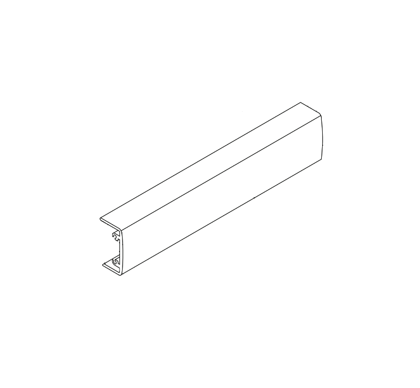
Adams Rite 8099 push bar assembly for narrow stile doors -- horizontal panic bar component used in narrow stile exit device assemblies

Adams Rite 8099 Push Bar Assembly for narrow stile door applications. View product page.


Exit devices are grouped by how they mount to the door and frame and how many latch points they engage. Choosing the right type depends on the door construction, frame material, and project requirements.


Rim Exit Device

A rim exit device mounts on the surface of the door and engages a frame-mounted strike through a single latch point. The chassis attaches to the door face and the latch projects into the strike on the door frame. Rim devices are the most common type and suit most standard commercial steel door and frame applications. They are available in standard panic hardware and fire exit hardware configurations.


Surface Vertical Rod (SVR) Exit Device

An SVR exit device uses external rods that run vertically on the door surface from the device chassis to top and bottom latches. When the bar is pressed, all latch points retract simultaneously. SVR devices suit wide or heavy doors where additional latch points improve security and door stability. The external rods are visible on the door surface.


Concealed Vertical Rod (CVR) Exit Device

A CVR exit device uses internal rods concealed within the door itself, running from the device chassis to top and bottom latches in the door edge. CVR devices require a door prepared with internal rod pockets. They provide a cleaner appearance than SVR devices because the hardware is not visible on the door surface. CVR devices are common in high-end or aesthetic applications where surface hardware is undesirable.


Mortise Exit Device

A mortise exit device integrates with a mortise lock body that is recessed into the door stile. The panic bar retracts the mortise latch when pressed. Mortise exit devices are used on thicker doors and in applications where the additional trim and function options of a mortise lock body are required. They are less common than rim or vertical rod devices in standard commercial applications.


Device TypeLatch PointsRods VisibleTypical Application
Rim1 (frame strike)NoStandard commercial steel doors and frames
SVR3 (top, bottom, latch)Yes -- external rodsWide or heavy doors, higher security requirements
CVR3 (top, bottom, latch)No -- concealed in doorAesthetic applications, doors prepared for concealed rods
Mortise1 (mortise latch)NoThick doors, applications requiring mortise lock functions

For guidance on how to install an exit device in rim, SVR, or CVR configuration, see the exit device installation guide.


Panic Hardware vs Fire Exit Hardware: An Important Distinction
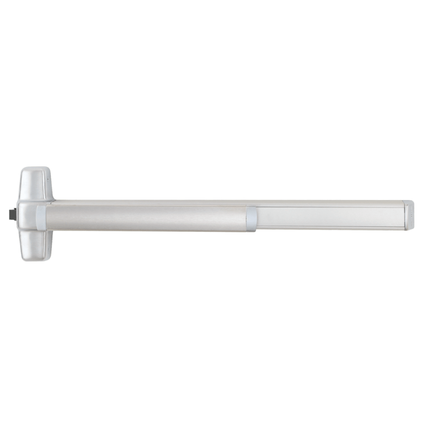
Von Duprin 98/99EO-F Rim Fire Exit Device -- fire exit hardware listed for installation on fire-rated door assemblies

Von Duprin 98/99EO-F Rim Fire Exit Device. Fire exit hardware listed for fire-rated door assemblies. Note the fire label on the device. View product page.


One area where the terminology matters more precisely is the distinction between standard panic hardware and fire exit hardware. These two device types look similar and operate on the same push-to-exit principle, but they serve different applications and carry different code and listing requirements.


Standard Panic Hardware

Standard panic hardware meets the egress hardware requirements of NFPA 101 and the IBC for non-fire-rated doors. It allows single-motion egress without a key and meets the grade and force requirements of ANSI/BHMA A156.3. Standard panic hardware may include a dogging feature that holds the latch retracted, allowing the door to operate as a push-pull door without pressing the bar each time.


Fire Exit Hardware

Fire exit hardware is required on fire-rated door assemblies. A fire-rated door assembly is a door, frame, and hardware combination that has been tested and listed for a specific fire rating (such as 20-minute, 45-minute, 90-minute, or 3-hour). When a fire-rated door requires egress hardware, the hardware must be listed as fire exit hardware to maintain the door's fire rating.

Fire exit hardware carries a fire label issued by a nationally recognized testing laboratory. The device itself must not allow dogging (holding the latch open), because a fire door must be self-latching to contain fire and smoke. This is one of the most important field distinctions: a standard panic hardware device with a dogging feature should not be installed on a fire-rated door in most jurisdictions.

Visually, the device types look nearly identical. The fire label on the device and the order model suffix (typically an "F" designation, such as "EO-F" rather than "EO") are the distinguishing identifiers. If you are replacing hardware on a fire-rated door, confirm that the replacement device carries the correct fire listing.

For a full explanation of fire door ratings and hardware requirements, see the commercial door fire rating guide.


Summary Comparison

FeatureStandard Panic HardwareFire Exit Hardware
Operating principlePush bar releases latchPush bar releases latch
Fire rating labelNot required (non-fire-rated doors)Required -- fire label affixed to device
Dogging featureMay be includedNot permitted -- door must be self-latching
Door applicationNon-fire-rated egress doorsFire-rated door assemblies only
Code term (NFPA 101)"Panic hardware""Fire exit hardware"
Code term (IBC)"Exit device""Fire exit hardware"
Visible identifierNo fire label on deviceFire label affixed to device body


When Is Panic Hardware Required by Code

Both the IBC and NFPA 101 define conditions under which panic hardware or exit devices are required on egress doors. The specific thresholds and occupancy types vary between code editions and are subject to local adoption and amendment. The following is a general summary for context, not a substitute for verifying the applicable code edition and authority having jurisdiction (AHJ) for a specific project.

Under both codes, panic hardware is generally required when an egress door serves an assembly occupancy or an educational occupancy with an occupant load of 50 or more persons. High-hazard occupancies typically require panic hardware regardless of occupant load. The applicable code for your jurisdiction determines the exact threshold and occupancy classifications.

When panic hardware is not code-required, exit devices are still often used on commercial egress doors because they provide convenient, fast egress and are well-suited for high-traffic openings. Code requirement and product choice are two separate decisions: the code determines whether panic hardware is mandatory; the opening conditions determine the best device type when hardware selection is otherwise discretionary.


Occupancy TypeGeneral Code TriggerDevice Type RequiredNote
Assembly (theaters, arenas, auditoriums)Occupant load 50+Panic hardware or fire exit hardwareFire-rated doors need fire exit hardware
Educational (K-12, universities)Occupant load 50+Panic hardware or fire exit hardwareVerify local amendments
High-hazard (certain industrial/storage)Typically any occupant loadPanic hardware or fire exit hardwareCheck applicable code edition
Business, retail, healthcare, governmentNot typically mandated; discretionaryExit device at specifier discretionFire-rated doors still need fire exit hardware

For a more detailed breakdown of panic hardware code requirements and installation conditions, see the panic hardware for commercial doors guide. For ANSI/BHMA grading and standards that govern exit device performance requirements, see the ANSI BHMA hardware standards guide.


Exit Device Mounting Configurations and Strike Hardware
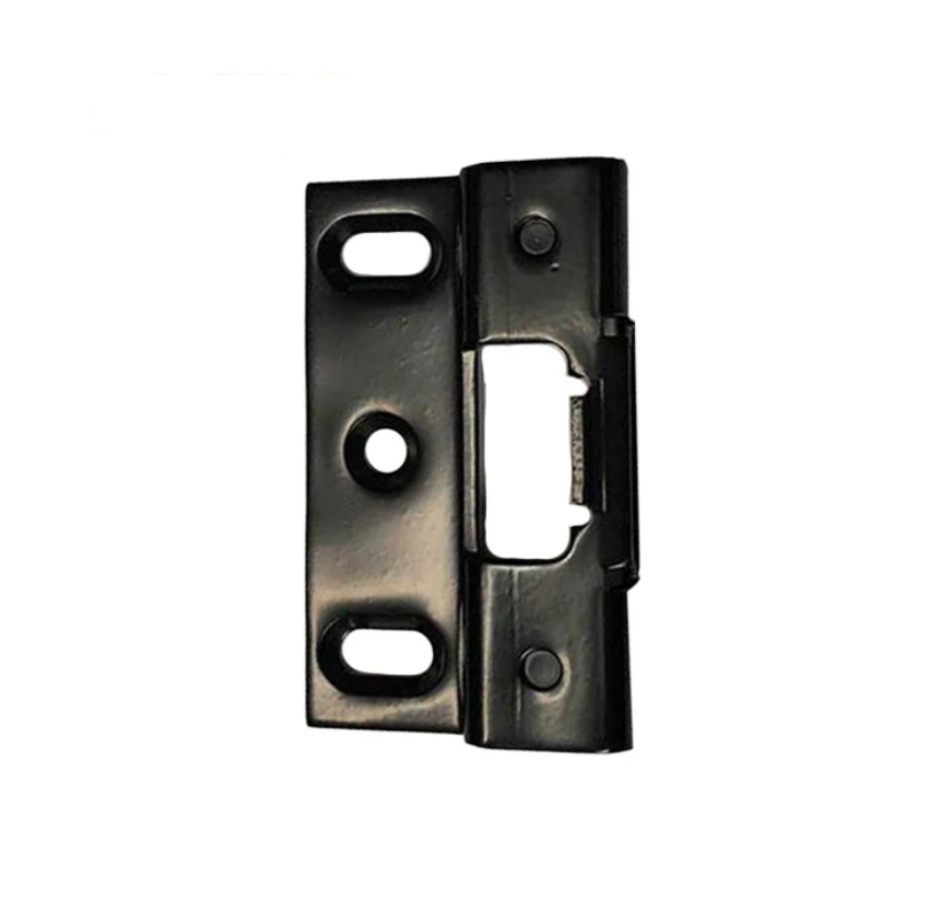
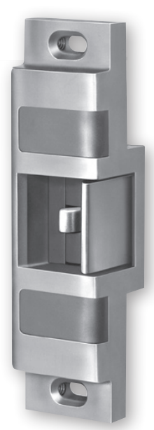
Adams Rite 22-0430 strike for rim exit device -- frame-mounted latch engagement component required for rim exit device installation

Adams Rite 22-0430 Strike for Rim Exit Device. The strike mounts on the door frame and receives the rim exit device latch when the door closes. View product page.


An exit device does not operate alone. The device mounted on the door requires a corresponding component on the door frame to complete the latch engagement. For rim devices, this is a rim strike mounted on the frame or mullion. For vertical rod devices, the top and bottom latches engage in floor and head frame strikes. Matching the correct strike to the device series and configuration is part of the parts ordering process.

Strikes are series-specific. A rim strike for one manufacturer's exit device series may not be compatible with a different series, even if the dimensions appear similar. Always verify the strike model against the device series when ordering replacement hardware.

For access control integration, exit devices can be electrified through electric latch retraction (EL) or connected to an electric strike. The choice between electrifying the device itself versus using an electric strike depends on the security requirements and the control logic of the access control system. For a full explanation of these options, see the access control and commercial door hardware integration guide.


Push Element Options: Bar, Touchbar, and Push Pad

Exit devices do not all use the same style of push element. The horizontal bar is the most common and widely recognized, but buyers will also encounter touchbar and push pad configurations.


Crossbar or Push Bar

The traditional crossbar extends across the full width of the door or at least half the door width as required by code. The bar is the most recognizable style and is used across nearly all device types. Push bars are replaceable components: the bar can be ordered separately to replace a damaged or worn push element without replacing the full device.


Touchbar

A touchbar is a slimmer, low-profile push element that is activated by a lighter touch. Touchbars are used where a sleeker appearance is preferred or where the reduced protrusion into the opening is an advantage. Some exit devices are designed specifically for touchbar configurations.


Push Pad

A push pad is a wider, flat panel that replaces the crossbar. Push pads are used on narrow stile aluminum doors and glass storefront applications where the door stile width does not accommodate a traditional crossbar assembly. The Adams Rite 8099 series is a common example of a narrow stile exit device that uses a push bar assembly sized for aluminum door stiles.


How to Identify Which Device Type You Have

Before ordering any replacement parts or a replacement device, confirm the model number of the installed unit. The model number is printed on a label affixed to the device chassis, typically on the side or back of the housing where it is visible when the door is open. The frame strike or the door edge may also carry a label.

Once you have the model number, confirm:

  • Whether the device is standard panic hardware or fire exit hardware (check for the fire label)
  • The mounting configuration (rim, SVR, CVR, or mortise)
  • The push element style (crossbar, touchbar, or push pad)
  • The outside trim configuration, if any (keylock, cylinder, thumbturn, or exit only)
  • The electrification option, if applicable (EL, QEL, MEL, or standard non-electrified)

These five data points determine the exact parts needed for any repair or replacement. Security Parts stocks exit device parts across multiple series and configurations. For part identification guidance organized by component category, see the exit devices parts guide.


Exit Devices by Building Type

Exit device type and configuration vary by building type, door construction, and code requirements. The following table summarizes common applications.

Building TypeCommon Device ConfigurationFire Rating Consideration
Schools and universitiesRim or SVR, panic hardware or fire exit hardwareCorridor and stairwell doors often fire-rated -- fire exit hardware required
Healthcare facilitiesRim or CVR, fire exit hardware commonHigh proportion of fire-rated doors -- verify each opening
Government buildingsRim or SVR; may include electrified optionsStairwell and rated corridor doors require fire exit hardware
High-rise office buildingsRim or mortise; stairwell re-entry doors need careful specificationMost stairwell doors are fire-rated -- fire exit hardware required
Retail and commercialRim, standard panic hardware; storefront may use narrow stile devicesVaries; verify each opening against door rating
Controlled access and delayed egressDelayed egress exit control lock or electrified exit deviceFire alarm release required; see delayed egress requirements

For application-specific guidance, see the healthcare door hardware guide, the K-12 school door hardware guide, and the government buildings door hardware guide. For delayed egress exit control lock requirements, see what is delayed egress.


Sourcing Exit Device Parts

Security Parts stocks exit device parts across Von Duprin, Falcon, Adams Rite, and Detex product lines. Replacement parts include push bar assemblies, latch assemblies, chassis components, outside trim kits, strike kits, glass bead kits, electrification modules, and dogging hardware.

Parts are series-specific. A Von Duprin 98/99 series push bar assembly is not interchangeable with a Falcon series push bar, even if the devices appear similar from the front. Confirm the device series and model number before ordering. Call 845-935-0301 for pre-order compatibility support if you are uncertain which parts match your installed device.

For the full Von Duprin 98/99 series parts catalog, see the Von Duprin 98/99 series exit device parts guide. For Detex exit control lock parts, see the Detex ECL parts guide. For troubleshooting a device that is not latching, binding, or operating correctly, see the commercial door hardware troubleshooting guide.


About the Author

This guide was written by the Security Parts team, a commercial door hardware specialist serving locksmiths, facilities managers, general contractors, and security integrators since 2001. Security Parts stocks exit device parts across Von Duprin, Falcon, Adams Rite, and Detex product lines, with same-day shipping on stocked components. For related guidance, see the panic hardware for commercial doors guide and the commercial door fire rating guide.
What Is Delayed Egress: How It Works, When Code Requires It, and Which Hardware to Specify

Quick Answer

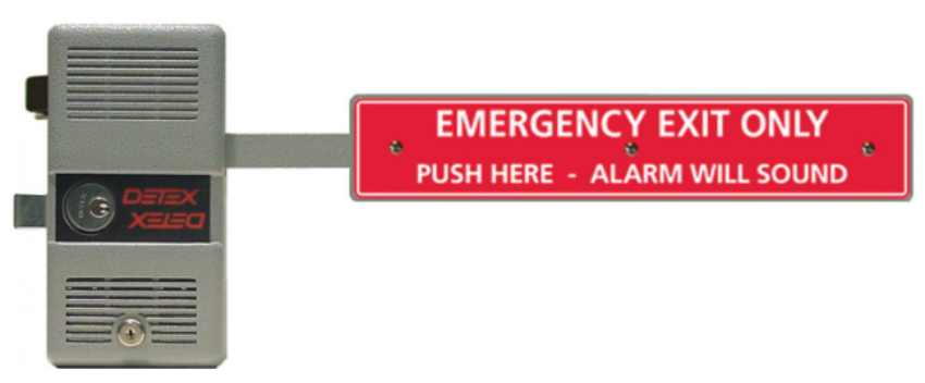
Delayed egress is a code-permitted door locking system that holds a door locked for a short timed period after someone pushes the exit touchbar. The device triggers a loud audible alarm when touched, then automatically releases the latch and allows free exit after 15 or 30 seconds, depending on the code and occupancy type. It is not a means of preventing egress permanently. It is a life safety compromise that gives facilities time to respond to an unauthorized or unassisted exit attempt while still guaranteeing egress within the code-permitted window.

Delayed egress is most commonly found in memory care units, dementia wards, schools, government buildings, and certain healthcare facilities. It is governed by NFPA 101 Section 7.2.1.6 and IBC Section 1010.1.9.8. All delayed egress devices must release immediately when the fire alarm activates or when power is lost.


How a Delayed Egress Device Works

A delayed egress device looks similar to a standard exit device: a horizontal touchbar or push plate mounted across the door, connected to a latch mechanism that releases when pressed. The critical difference is the internal timing mechanism and alarm circuit.

Here is the sequence of events when someone pushes a delayed egress door:

  • Touchbar contact: The person presses the touchbar or push plate. The door does not open immediately.
  • Alarm activation: Within one second of touchbar contact, a built-in alarm sounds at the door. The alarm is loud enough to alert staff in an adjacent area. Some models also send a signal to a remote annunciator panel.
  • Delay period: The door remains locked during the delay period. Under NFPA 101, the maximum permitted delay is 15 seconds. Under the IBC in jurisdictions that permit an extended delay, the maximum is 30 seconds for approved occupancy types.
  • Automatic release: After the delay period expires, the latch retracts automatically and the door opens freely. The person does not need to maintain pressure on the touchbar throughout the delay. A single push is sufficient to start the timing sequence.
  • Reset: When the door returns to the closed position, the device resets automatically to the locked state, ready for the next cycle.

The device must be powered, typically by 24VDC from the building's security or access control power supply. When power is removed, the device defaults to free egress with no delay (fail-safe). When the fire alarm activates, the device receives a release signal from the fire alarm panel and immediately retracts the latch, bypassing the delay entirely.


NFPA 101 Section 7.2.1.6: Plain-Language Explanation

NFPA 101, the Life Safety Code, is the primary code governing delayed egress in the United States. Section 7.2.1.6 sets the conditions under which a delayed egress locking system is permitted.

In plain terms, the code says the following:

  • The delayed egress system is only permitted where the building is protected throughout by an approved automatic fire suppression system or an approved automatic fire detection system.
  • The maximum delay is 15 seconds from the time the touchbar is pressed until the door releases.
  • The device must sound an audible alarm at the door when the touchbar is pressed.
  • The device must release immediately when the fire alarm system activates anywhere in the building, not just in the zone where the door is located.
  • The device must release immediately when power to the device is lost.
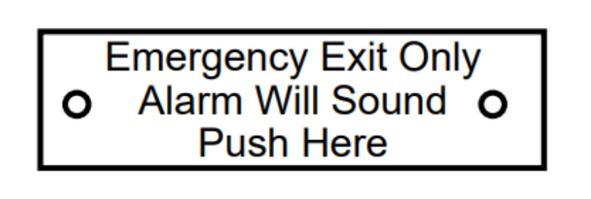
  • The door must be provided with a readily visible posted sign that tells users the alarm will sound and the door will open after the delay period. This sign is not optional.
  • Only one such device may be installed on any egress path, meaning a person cannot be required to pass through more than one delayed egress door before reaching a public way or area of refuge.

The specific occupancy chapters of NFPA 101 also affect where delayed egress is permitted. The general rule in Section 7.2.1.6 permits delayed egress in specific occupancy types. The AHJ has authority to approve or deny the installation based on the occupancy classification and the building's fire protection systems.


IBC Section 1010.1.9.8: Plain-Language Explanation

The International Building Code (IBC), adopted in most US jurisdictions, addresses delayed egress in Section 1010.1.9.8. The IBC provisions are largely consistent with NFPA 101 but include one significant difference: the permitted delay can extend to 30 seconds in specific occupancy types when approved by the AHJ.

In plain terms, the IBC says the following:

  • Delayed egress is permitted only where the building is equipped throughout with an automatic sprinkler system or an approved fire detection system.
  • The locking system must release when a signal is received from the sprinkler system, the fire detection system, or a manual fire alarm initiation device.
  • The system must release upon loss of power controlling the lock.
  • The required signage must be posted on the door at an approved location and in an approved format.
  • A 15-second delay applies by default. A 30-second delay is permitted for Group I-1 (assisted living, residential care), Group I-2 (hospitals, nursing facilities), Group I-3 (detention and correctional facilities), and Group R-1 (hotels) occupancies when specifically approved by the AHJ.
  • Only one delayed egress device may be encountered on any single egress path to the public way.


The 15-Second vs 30-Second Delayed Egress Rule

The distinction between a 15-second and 30-second delay is one of the most common specification questions for delayed egress projects.

Delay SettingCode AuthorityTypical ApplicationAHJ Approval Required
15 secondsNFPA 101, IBC (default)Most commercial, educational, government, and healthcare buildingsYes -- AHJ must approve delayed egress for the occupancy type
30 secondsIBC Section 1010.1.9.8 (extended)Memory care units, dementia wards, assisted living, hospitals, detention facilities, hotelsYes -- AHJ must specifically approve the 30-second delay for the occupancy group

The 30-second delay exists primarily for memory care and dementia applications, where a resident may attempt to exit but will typically stop or turn back within 30 seconds when staff responds. In these settings, a 15-second delay may not give staff adequate response time before the door releases.

The Detex ECL-230X series supports both 15-second and 30-second delay settings. Confirm with the AHJ which setting is approved for the specific occupancy before specifying or installing the device. For detailed parts information on the ECL-230X series, see the Detex ECL parts guide.


Delayed Egress vs Free Egress: What Is the Difference

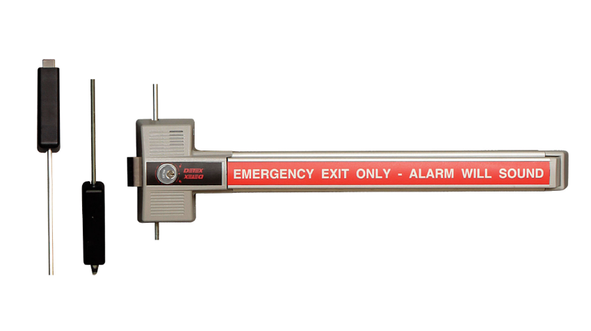
Detex ECL-230X-TDB 3-point delayed egress exit control lock for commercial doors requiring timed egress

Detex ECL-230X-TDB 3-Point Delayed Egress Exit Control Lock. View product page.


Most commercial exit devices provide free egress: push the bar and the door opens immediately. Delayed egress is a specific modification to that behavior, permitted only in certain building types and only with AHJ approval.


FeatureFree Egress DeviceDelayed Egress Device
Door opens whenImmediately on touchbar contactAfter 15 or 30 seconds
Alarm on touchbar contactNo (dogged devices are silent)Yes -- within 1 second of contact
Fire alarm behaviorNo change (already free egress)Immediate latch release, no delay
Power failure behaviorNo changeImmediate latch release, no delay
Required posted signageStandard exit signage onlyCode-compliant delayed egress sign required
AHJ approvalNot required for standard useRequired for every installation
Occupancy restrictionMost occupancy typesSpecific occupancy types only
Per-egress-path limitNo limitMaximum one delayed egress door per egress path

For broader context on exit device types and how to select the right one for your opening, see the exit devices parts guide and the panic hardware for commercial doors guide.


What Happens During a Fire Alarm, Power Failure, and Reset

Fire Alarm Release

A delayed egress device must be wired to the building fire alarm panel. When the fire alarm activates anywhere in the building, the fire alarm panel sends a release signal to every delayed egress device in the system. All delayed egress doors release immediately and revert to standard push-to-exit operation with no delay and no alarm requirement. This release must happen regardless of whether a touchbar has been pressed or a delay sequence is in progress.

If the building's fire alarm panel trips during an active delay sequence, the delay is cancelled immediately and the door opens. People do not have to wait out the remaining delay during a fire event.

Confirm that the fire alarm integration wiring is completed and tested before the delayed egress system is put into service. A delayed egress device that is not connected to the fire alarm system does not meet the code requirements of NFPA 101 Section 7.2.1.6 or IBC Section 1010.1.9.8 and cannot be legally installed on an egress path.


Power Failure Release

Loss of power to the delayed egress device causes the latch to release and the door to revert to free egress. This fail-safe behavior is required by both NFPA 101 and the IBC. The device cannot hold the door locked without power.

The Detex ECL-230X series operates on 24VDC and requires continuous power to maintain the delayed egress locking function. When power is removed, the device releases within milliseconds and the door operates as a standard push-to-exit device.

Some ECL installations include battery backup to maintain alarm annunciation capability during brief power interruptions. However, battery backup does not change the fail-safe locking behavior: the door must release on power loss, even if the battery is powering auxiliary functions.


Reset After a Delay Cycle

After a completed delay cycle (when someone pushes the bar and the door opens after the delay), the device resets automatically when the door returns to the closed and latched position. No manual action is required to reset the device to the delayed egress state. The device is ready for the next cycle as soon as the door is closed.

Some ECL models require a manual reset by staff using an authorized key or credential if the device has been triggered. Confirm the reset behavior of the specific model when specifying or installing the device, since this affects how staff workflows are designed around the door.


Where Delayed Egress Is Used: Building Types and Applications

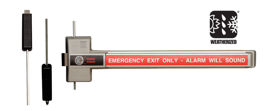
Detex ECL-230X-W-TDB weatherized 3-point delayed egress exit control lock for exterior doors and covered egress paths

Detex ECL-230X-W-TDB Weatherized 3-Point Delayed Egress Lock for exterior applications. View product page.


Building TypeTypical ApplicationCommon Delay SettingNotes
Healthcare -- Memory Care and Dementia UnitsPerimeter exit doors, unit entry/exit doors30 seconds (IBC Group I-1/I-2)Most common application; 30-second delay requires AHJ approval
Healthcare -- Hospitals and Nursing FacilitiesPsychiatric unit doors, behavioral health exits15 or 30 secondsDelay setting depends on occupancy classification and AHJ
K-12 SchoolsExterior exit doors, perimeter doors during school hours15 secondsUsed to monitor unauthorized student exits; alarms alert staff
Universities and CollegesDormitory perimeter doors, controlled campus exits15 secondsCommonly installed with access control integration for after-hours monitoring
Government BuildingsControlled area exits, file room perimeter doors15 secondsUsed to monitor exits from restricted areas without fully restricting egress
High-Rise BuildingsStairwell re-entry doors, controlled floor exits15 secondsMust meet NFPA 101 high-rise provisions; fire alarm integration is critical
Retail and CommercialLoss prevention exits, back-of-house egress doors15 secondsAHJ approval required; typically used on secondary egress paths only
Detention and Correctional FacilitiesControlled egress from detention areas15 or 30 seconds (IBC Group I-3)Special IBC provisions apply for this occupancy type

For application-specific guidance on commercial door hardware requirements, see the healthcare door hardware guide, the K-12 school door hardware guide, the universities door hardware guide, the government buildings guide, and the high-rise buildings guide.


Delayed Egress Signage: What the Code Requires

Detex ECL-230X-TB 2-point delayed egress exit control lock for interior commercial door applications

Detex ECL-230X-TB 2-Point Delayed Egress Exit Control Lock for interior applications. View product page.


Both NFPA 101 Section 7.2.1.6 and IBC Section 1010.1.9.8 require that a compliant sign be posted on every delayed egress door. The sign is not optional and is not satisfied by standard exit signage.

The required sign must communicate the following to anyone approaching the door:

  • Pushing the bar will activate an alarm
  • The door will open after a specified number of seconds (15 or 30, as applicable)
  • The information must be clear, readable, and positioned where someone approaching the door will see it before pushing the bar

The Detex ECL-395 series provides code-compliant delayed egress door signs available in multiple languages: English, Spanish, French, French-Canadian, and German. These signs are listed by code as a requirement accompanying every delayed egress installation, not as an accessory upgrade. An installation that has a delayed egress device but lacks the required posted sign fails the code requirements of NFPA 101 and the IBC and will be flagged during any AHJ inspection.

The sign must be inspected annually to confirm it is intact, legible, and properly positioned. A torn, missing, faded, or obstructed sign is a code deficiency even if the device itself is functioning correctly.


2-Point vs 3-Point Delayed Egress: Which Model to Choose

The Detex ECL-230X series is available in two primary locking configurations: 2-point (single latchbolt) and 3-point (top, bottom, and latchbolt). Choosing the correct configuration depends on the door type and the security and code requirements of the opening.


2-Point Delayed Egress (ECL-230X-TB / ECL-230X-W-TB)

Detex ECL-230X-W-TB weatherized 2-point delayed egress exit control lock for exterior commercial door applications

Detex ECL-230X-W-TB Weatherized 2-Point Delayed Egress Lock. View product page.

The 2-point model uses a single latchbolt at the device chassis, engaging one strike point on the door frame. This is the standard configuration for most interior delayed egress applications where the door and frame are in good condition and the single latch is sufficient to hold the door during the delay period. The weatherized version (ECL-230X-W-TB) is appropriate for exterior applications exposed to weather.


3-Point Delayed Egress (ECL-230X-TDB / ECL-230X-W-TDB)

The 3-point model adds top and bottom latching in addition to the chassis latch, providing three points of engagement against the frame. This configuration is used when additional door stability is required during the delay period, when the door gap is inconsistent due to door warping, or when the AHJ or security integrator requires multi-point engagement for higher-security delayed egress applications.

ModelLatch PointsWeatherizedTypical UseProduct Page
ECL-230X-TB2-pointNoInterior doorsView
ECL-230X-W-TB2-pointYesExterior / covered egress pathsView
ECL-230X-TDB3-pointNoInterior doors requiring multi-point engagementView
ECL-230X-W-TDB3-pointYesExterior doors requiring multi-point engagementView

For replacement parts, mechanism assemblies, strike kits, bar components, and accessory kits for all ECL-230X models, see the complete Detex ECL parts guide.


Annual Inspection and Testing Checklist for Delayed Egress Devices

NFPA 101 requires annual inspection and testing of life safety features including delayed egress systems. NFPA 80 also requires annual inspection of fire-rated door assemblies, which includes any delayed egress device installed on a fire-rated door. Written records of each inspection must be maintained and made available to the AHJ upon request.

For the complete commercial door hardware maintenance schedule, see the commercial door hardware maintenance checklist.


Functional Operation Test

  • Push the touchbar and confirm the alarm activates within one second of contact
  • Time the delay from touchbar contact to latch release. Confirm the measured delay matches the programmed setting (15 or 30 seconds)
  • Confirm the door opens freely after the delay period without requiring a second push
  • Allow the door to close and confirm it returns to the latched and delayed egress state automatically


Fire Alarm Release Test

  • With the delayed egress device activated (during the delay sequence), trigger a test signal from the fire alarm panel
  • Confirm the latch releases immediately upon receiving the fire alarm signal
  • Confirm the door operates as a standard free egress device with no delay during the fire alarm signal
  • Reset the fire alarm panel and confirm the delayed egress device returns to normal operation
  • This test must be performed in coordination with the building fire alarm system contractor or the AHJ


Power Failure Release Test

  • Disconnect power to the delayed egress device at the power supply
  • Confirm the latch releases immediately and the door opens freely
  • Reconnect power and confirm the device returns to normal delayed egress operation when the door is closed and latched


Signage Inspection

  • Confirm the required delayed egress sign is present, intact, and legible
  • Confirm the sign is positioned where it is visible to anyone approaching the door from the egress side
  • Confirm the sign specifies the correct delay period (15 or 30 seconds as applicable)
  • Replace any sign that is torn, faded, obstructed, missing, or specifies the incorrect delay period


Physical Inspection

  • Inspect the touchbar or push plate for physical damage, wear, or looseness
  • Check all mounting fasteners for tightness
  • Inspect the strike kit and latch engagement for alignment and wear
  • Confirm the alarm speaker is unobstructed and produces audible output at the required sound level
  • Inspect all wiring connections at the device and at the power supply for corrosion or looseness
  • Document all inspection results and note any deficiencies found and corrected


Where to Source Delayed Egress Hardware and Replacement Parts

Security Parts stocks Detex ECL-230X delayed egress exit control locks in all four configurations (2-point standard, 2-point weatherized, 3-point standard, 3-point weatherized) and stocks 59 ECL-series replacement parts including internal mechanism assemblies, bar and paddle components, strike kits, cover and shield assemblies, outside trim, cylinder components, accessory kits, and code-required delayed egress door signs.

For the complete parts catalog organized by component category, see the Detex ECL parts guide. For general exit device parts and component identification, see the exit devices parts guide. For guidance on exit device installation, see the exit device installation guide. For troubleshooting a delayed egress device that is not functioning correctly after installation, see the commercial door hardware troubleshooting guide.

Call 845-935-0301 for pre-order compatibility support when selecting replacement parts for an existing ECL installation.


About the Author

This guide was written by the Security Parts team, a commercial door hardware specialist serving locksmiths, facilities managers, general contractors, and security integrators since 2001. Security Parts stocks Detex ECL-230X delayed egress exit control locks in all configurations and 59 ECL-series replacement parts, with same-day shipping on stocked components and pre-order compatibility support at 845-935-0301. For related guidance, see the commercial door fire rating guide and the access control and commercial door hardware integration guide.

How to Install an Exit Device: Step-by-Step Guide for Rim, SVR, and CVR Configurations

Quick Answer

Installing an exit device on a commercial door requires four things done in the right order: confirm your device type and handing before touching the door, mount the chassis at the correct height (touchpad centerline between 34 and 48 inches above finished floor per ANSI A156.3), install the appropriate strike for your configuration (rim, surface vertical rod, or concealed vertical rod), and verify latch engagement and egress force before the door goes back into service.

The steps differ for each device type. Rim devices mount at one point; surface vertical rod (SVR) devices require top and bottom rod adjustment; concealed vertical rod (CVR) devices require factory-prepped door pockets. Start with this guide from the beginning so you are following the correct steps for your specific installation.


Before You Start: Identify Your Exit Device Configuration

The most expensive exit device installation mistake happens before the first hole is drilled: a contractor starts the wrong set of steps because they did not confirm the device type. Rim, SVR, and CVR devices share some installation principles but have completely different strikes, rods, and door prep requirements. Confirm your device type first.

Rim exit device on a commercial door showing the chassis mounted to the door face with a single latch point

A rim exit device mounts to the door face and latches at one point. See the exit devices parts guide for component identification.


Rim Exit Device

A rim device mounts directly to the door face and latches at one point only. The strike mounts to the door frame. When the touchpad or crossbar is pushed, the latch retracts and the door swings free. Rim devices are the most common configuration and the simplest to install. Look for a single horizontal crossbar across the door width and a surface-mounted chassis on the door face. Common series identifiers: 98, 99, F-98, F-99, 22, 33A.


Surface Vertical Rod (SVR) Exit Device

A surface vertical rod device latches at two points: a top latch that engages the top frame and a bottom bolt that drops into a floor strike or threshold strike. The rods run vertically on the door face. SVR devices are used on doors without a center mullion or on pairs of doors where the active leaf requires multi-point latching. Look for exposed vertical rods running from the chassis to the top and bottom of the door. Common series identifiers: 9827, 9927, 27-series.


Concealed Vertical Rod (CVR) Exit Device

A concealed vertical rod device also latches at top and bottom, but the rods run inside the door cavity rather than on the surface. CVR installations require the door to have factory-prepped mortise pockets for the top latch assembly and a cutout for the bottom bolt. If the door does not arrive pre-prepped, field prep is significantly more involved. Look for a device with no visible rods on the door face. Common series identifiers: 9847, 9947, 47-series.

For help identifying which exit device series is installed or which series to order for a replacement, see the Von Duprin exit device series comparison and the Von Duprin panic bar selection guide.


What You Need: Tools and Materials Checklist

Required Tools

  • Drill with bit set (1/4-inch and 3/8-inch bits for through-bolt applications)
  • Tape measure
  • 4-inch torpedo level or longer spirit level
  • Pencil or punch awl for marking
  • Phillips and flathead screwdrivers
  • Allen/hex key set (for dogging slot and trim screws)
  • Nut driver or adjustable wrench (for through-bolt nuts)
  • Threadlocker compound (for through-bolt applications on hollow metal doors)
  • Chisel (for CVR top latch pocket if door is not pre-prepped)
  • Center punch (for accurate pilot hole placement on metal doors)


Materials to Have On Hand Before Starting

  • Exit device with all included hardware (confirm nothing is missing before opening the door)
  • Manufacturer installation template for the exact series being installed
  • Correct strike for the device series (rim strike, top strike, bottom strike/floor box as applicable)
  • Through-bolt kit if the door does not include it
  • Backplate (required on thin hollow metal doors to prevent chassis deformation)
  • For SVR: additional rod length if the door is taller than standard
  • For CVR: edge prep kit if the top latch pocket is not factory-installed


Pre-Install Inspection Checklist

Running through this checklist before mounting prevents the two most common failed installations: wrong handing and a device that does not match the door prep. Both require sending the device back for exchange, which costs more time than checking takes.


Confirm the Handing

Stand inside the room facing the door from the secure side, meaning the side the door swings away from you. If the hinges are on your right, the door is right-hand (RHR or RH). If the hinges are on your left, the door is left-hand (LHR or LH). The handing of the exit device must match the door handing.

The handing designation is printed on the device carton label and on the chassis identification label inside the device. Confirm the carton label matches the door before opening packaging. Some exit device series are field-reversible by flipping the latch or lever trim; others are factory-handed and cannot be changed in the field. If the handing is wrong on a non-reversible device, do not mount it. Contact the supplier before proceeding.


Confirm the Door Prep

  • Door width: Confirm the chassis length fits the door width. Most exit devices are available in standard widths (typically 36-inch and 48-inch door widths). A chassis that overhangs the door edge will not mount correctly.
  • Door thickness: Through-bolt lengths and faceplate depths are door-thickness specific. Confirm the through-bolt length in the kit matches the actual door thickness before drilling.
  • For CVR devices: Confirm the top latch mortise pocket dimensions and the bottom bolt cutout match the device specification. Measure the pocket depth, width, and location against the manufacturer template before mounting the chassis.
  • For SVR devices: Confirm the rod lengths shipped with the device match the door height. Rods ship at maximum length and must be cut or adjusted down.


Inspect the Device Before Mounting

  • Check the touchpad or crossbar for shipping damage (bent bar, cracked end cap, missing trim screws)
  • Confirm latch projection by measuring from the latch face to the device faceplate. Standard latch projection is 5/8 inch. Confirm this matches the strike clearance on your frame.
  • Verify that all rods, end caps, trim screws, through-bolts, and the installation template are in the packaging
  • Confirm the included strike matches the device series. Strikes are series-specific and not interchangeable between device families


Exit Device Mounting Height Requirements

Mounting height is the most-searched specific installation question for exit devices, and the most common source of a code-noncompliant installation.

ANSI A156.3 Height Requirement

ANSI A156.3 requires the touchpad or crossbar centerline to be between 34 and 48 inches above the finished floor. This measurement is taken to the push element itself, not to the device chassis or the top of the touchbar. A device chassis mounted with its center at 38 inches may have a touchpad centerline at 36 inches, depending on the chassis design. Always measure to the push element after mounting, not to the chassis center.

The 34-to-48-inch range also satisfies ADA Section 404.2.7 for accessible door hardware. An exit device within this range does not require an additional accessible pull or lever on the push side.


Mounting Height Reference by Door Height

Door HeightRecommended Chassis Mounting CenterPush Element Centerline Target
7 ft (84 in)38--40 in from finished floor36--40 in (verify after mounting)
8 ft (96 in)38--42 in from finished floor36--42 in (verify after mounting)
9 ft (108 in)40--44 in from finished floor38--44 in (verify after mounting)
Any heightAdjust to keep push element within 34--48 in34--48 in (ANSI A156.3 absolute range)

For ANSI and BHMA hardware standard context, see the ANSI/BHMA door hardware standards guide.


Marking the Mounting Height on the Door

Use the manufacturer installation template for your device series. Position the template at the target height with the push element centerline mark at the intended measurement. Confirm the template is level before marking any holes. Mark all hole center points with a pencil or punch awl before drilling. On metal doors, use a center punch to prevent bit walk when drilling.


Metal Door vs Wood Door Installation Differences

Hollow Metal Door Installation

Through-bolt mounting is required on hollow metal (HM) doors. The hollow interior of the door does not provide enough thread engagement for wood screws or short machine screws to resist the repeated lateral force applied to the exit device during daily egress cycles. Through-bolts pass completely through the door and are secured with nuts on the interior face.

  • Use the through-bolt kit supplied with the device or ordered separately for the series
  • A backplate on the interior door face is required on thin hollow metal doors (typically 14 gauge or thinner) to prevent the through-bolt nuts from pulling through the door face under load
  • Apply threadlocker compound to through-bolt threads before tightening. Vibration from repeated door operation can loosen nuts over time without it
  • Tighten nuts to the manufacturer-specified torque (typically 60--80 in-lb). Do not over-tighten, which can deform the chassis or door face


Wood Door Installation

Solid core wood doors can use the machine screws provided with the exit device in most cases. However, through-bolt mounting is still recommended on high-cycle openings or any door that will see heavy commercial traffic.

  • Pilot holes should be drilled at 70--80% of the screw diameter to prevent splitting on solid wood doors
  • Minimum door thickness for adequate thread engagement is typically 1-3/4 inches. Confirm the fastener length in the kit is appropriate for the actual door thickness
  • On doors with veneer or laminate faces, over-tightening can crack or delaminate the surface. Tighten just until the chassis is firmly seated


Aluminum Storefront and Glass Doors

Exit devices on aluminum storefront frames require a device series specifically listed for that door and frame type. Standard exit device hardware is not designed for narrow stile aluminum extrusions. Glass doors with patch fittings require a device series compatible with the patch dimensions. Confirm the device series listing before ordering for any aluminum or glass door application.


How to Install a Rim Exit Device (Step by Step)

Rim installation is the most straightforward of the three device types. The device mounts to the door face with through-bolts, and the rim strike mounts to the door frame. For Von Duprin 98/99 series rim device components, see the Von Duprin 9899 series parts guide. For Falcon 19, 24, and 25 series rim devices, see the Falcon 19/24/25 series exit device parts guide.


Step 1: Prepare the Door and Apply the Template

Position the manufacturer installation template on the door face at the target mounting height. The template shows the hole pattern for the specific device series. Confirm the template is oriented correctly for the door handing (RHR or LHR). Use the template center marks to align the push element centerline at the intended height. Hold the template in position and mark all hole centers with a pencil. Confirm the level before marking.


Step 2: Drill Mounting Holes

On hollow metal doors, use a center punch at each marked location before drilling to prevent bit walk. Drill pilot holes for through-bolts using the bit diameter specified in the installation template (typically 1/4 inch for standard through-bolts). On wood doors, drill pilot holes at 70--80% of screw shank diameter. Clear all chips before proceeding.


Step 3: Mount the Chassis to the Door Face

Set the device chassis against the door face with all holes aligned. Insert through-bolts (or screws on wood doors) through the chassis and door. Start all fasteners before tightening any of them. Once all fasteners are started, tighten in a cross pattern to draw the chassis evenly against the door face without rocking. Apply threadlocker to through-bolt threads on metal doors before tightening the nuts.


Step 4: Install the Rim Strike on the Door Frame

Hold the door in the closed position and mark the strike location on the door frame by pressing the door gently against the frame and transferring the latch centerline. The rim strike must align with the latch both vertically and laterally. Fasten the strike to the frame with the provided fasteners. Most rim strikes have slotted holes for minor vertical adjustment.


Step 5: Set the Latch Projection and Strike Alignment

Close the door and observe how the latch enters the strike. The latch should enter cleanly and engage the strike keeper without rolling back or dragging on the strike lip. If the latch rolls back (does not engage), the strike is too far from the frame face. If the latch drags, the strike is too close or misaligned vertically. Adjust strike position as needed and re-fasten.


Step 6: Secure All Fasteners and Verify Operation

Fully tighten all through-bolt nuts and mounting screws. Operate the touchpad 10 times in succession and confirm the latch retracts fully and consistently each time. Confirm the door latches fully when closed without requiring any pressure on the door face. Proceed to the post-install testing checklist.


How to Install a Surface Vertical Rod (SVR) Exit Device (Step by Step)

SVR installation adds two additional steps to the rim process: top and bottom rod length adjustment. The rods ship at maximum length and must be shortened or adjusted to the actual door height. For Von Duprin 22-series, 33A, 35A, and 55-series SVR devices, see the Von Duprin 22/33A/35A/55 series exit device parts guide.


Step 1: Prepare the Door and Confirm Rod Lengths

Apply the installation template at the target mounting height and mark all chassis holes. Before drilling, hold the device against the door and extend the top rod toward the top frame and the bottom rod toward the floor. Confirm the rods reach their respective strikes with the device chassis at the target mounting position. If the door height is less than the maximum rod length, note the adjustment needed.


Step 2: Mount the Chassis to the Door

Follow Steps 1 through 3 from the rim installation procedure above. The chassis mounting process is identical. Confirm the chassis is level before fully tightening through-bolt nuts.


Step 3: Attach and Adjust the Top Rod Assembly

Connect the top rod to the chassis rod connection point. Run the rod toward the top of the door. Most SVR top rods have a threaded coupler at the strike end that allows length adjustment. Thread the coupler in or out until the top latch engages the top strike correctly when the touchpad is released. Confirm the top latch retracts fully when the touchpad is pressed.


Step 4: Attach and Adjust the Bottom Rod Assembly

Connect the bottom rod to the chassis and run it toward the floor. The bottom rod connects to the floor bolt, which drops into a floor strike or threshold strike. Adjust the rod length so the floor bolt drops cleanly into the floor strike and engages fully when the touchpad is released. The bottom bolt should retract fully when the touchpad is pressed. Confirm both rod connections are tight after adjustment.


Step 5: Install Top and Bottom Strikes

Install the top strike in the header frame at the height required to align with the top latch centerline. Install the floor strike (or threshold strike) at the floor position aligned with the bottom bolt centerline. Both strikes typically have slotted mounting holes for minor alignment adjustment.


Step 6: Set Rod Tension and Test Both Latch Points

Operate the touchpad and confirm both the top latch and the bottom bolt retract simultaneously and fully. Close the door and confirm both latch points engage their respective strikes cleanly. Adjust top or bottom rod length if either latch point drags, rolls back, or fails to engage fully.


How to Install a Concealed Vertical Rod (CVR) Exit Device (Step by Step)

Von Duprin 9947 concealed vertical rod exit device showing the chassis and internal rod configuration for commercial door installation

Von Duprin 98/9947 CVR exit device. Rods are concealed inside the door cavity. View product page. For all CVR replacement parts, see the Von Duprin 9947 CVR exit device parts guide.


CVR installation is the most complex of the three types because the rods run inside the door cavity and the door must be pre-prepped with specific pockets and cutouts. Do not attempt CVR installation on a door that has not been factory-prepped or field-prepped to the manufacturer's specifications.


Step 1: Confirm Door Prep (Top Latch Pocket and Bottom Bolt Cutout)

Measure the top latch mortise pocket (typically at the top of the door edge) against the manufacturer's dimension specifications. Confirm the pocket depth, width, and distance from the door top match the CVR device requirements. Measure the bottom bolt cutout at the door bottom edge and confirm it aligns with the floor strike location. If either prep dimension is incorrect, field modification is required before mounting the chassis.


Step 2: Mount the Chassis to the Door

Apply the installation template and mark all chassis mounting holes. Drill and mount the chassis using the same through-bolt process as rim and SVR installation. Confirm the chassis is level and fully seated before tightening.


Step 3: Route and Connect the Top Latch Assembly

Feed the top latch assembly up through the door cavity to the top latch pocket. Connect the top rod to the chassis drive mechanism and route it through the door interior. Seat the top latch housing in the top pocket and fasten it according to the manufacturer specification. Confirm the top latch retracts when the touchpad is pressed and extends fully when released.


Step 4: Route and Connect the Bottom Bolt Assembly

Feed the bottom bolt assembly down through the door cavity to the bottom cutout. Connect the bottom rod to the chassis drive and route it to the bottom bolt housing. Seat the bottom bolt housing in the bottom cutout and fasten it. Confirm the bottom bolt drops fully when the touchpad is released and retracts fully when the touchpad is pressed.


Step 5: Install Top and Bottom Strikes

Install the top strike in the header frame at the correct height for the top latch centerline. Install the floor strike aligned with the bottom bolt centerline. Both strikes must account for the latch projection depth of the CVR device, which may differ from the SVR projection depth on the same door configuration.


Step 6: Check Bolt Engagement and Adjust

Close the door and verify that both latching points engage cleanly. Cycle the touchpad 10 times and confirm both the top latch and bottom bolt retract and extend consistently. Adjust rod connections at the chassis if either bolt is not traveling the full stroke. Confirm all interior fasteners on the latch and bolt housings are tightened before final inspection.


Dogging the Exit Device After Installation

Von Duprin 090040 hex dogging shaft package used to dog an exit device in the unlocked position    Von Duprin 107813 cylinder dogging kit for key-operated mechanical dogging on commercial exit devices

Left: Von Duprin 090040 hex dogging shaft. Right: Von Duprin 107813 cylinder dogging kit. Both are used for mechanical dogging on standard (non-fire-rated) openings.


Dogging holds the exit device latch in the fully retracted position so the door operates as a standard push-pull door without requiring touchpad pressure. It is typically engaged during business hours and released after closing. Dogging is set after installation, not before.


What Dogging Does

When the latch is dogged, the touchpad or crossbar is held in the depressed position mechanically. The door swings freely in both directions without any requirement to push the touchpad. This is the normal daytime operating mode for high-traffic openings that do not require controlled egress during business hours.


Mechanical (Hex Key) Dogging

The dogging slot is located on the face of the chassis near the touchpad connection. Insert a 3/32-inch hex (Allen) key into the dogging slot and turn it to lock the touchpad in the depressed position. The hex key is removed after dogging; the device stays dogged until the key is reinserted and turned to release.

Mechanical dogging is not permitted on fire-rated openings. A fire door must self-latch every time it closes, and mechanical dogging defeats that requirement. If a fire-rated opening needs free-swing daytime operation, electric dogging is the only compliant option.


Electric Dogging (QEL and MEL Options)

Electric dogging uses an internal solenoid to hold the latch retracted under access control command. When power is cut or the fire alarm triggers, the solenoid releases and the device returns to full latching function. QEL (quiet electric latch retraction) and MEL (motor-driven electric latch retraction) are the two common electric dogging options. For the difference between the two and which to specify, see the Von Duprin QEL vs MEL guide and the access control and commercial door hardware integration guide.


Electric Strike Alignment for Exit Devices

When an exit device is paired with an electric strike for access control, the strike and the device latch must be aligned before the installation is complete. Misalignment is the most common cause of a latch that functions correctly under hand operation but fails to engage reliably under normal door operation. For electric strike replacement parts, see the electric strike parts guide.


Rim Device and Electric Strike Alignment

The rim strike cutout must align with the rim latch both laterally and vertically. With the door in the closed position, confirm that the latch centerline aligns with the center of the electric strike keeper opening. Most electric strikes have a small adjustment range within the frame pocket. Use this range to center the keeper on the latch before final fastening.


Vertical Rod Device and Electric Strike

On SVR and CVR installations, the electric strike typically electrifies only the top latch. The bottom bolt remains mechanical and always extends when the door closes. The top latch alignment process is the same as for a rim device: confirm the top latch centerline aligns with the electric strike keeper centerline before final fastening. The bottom floor strike is installed mechanically and does not require electrical connection.


Testing the Strike and Device Together

Before energizing the strike, confirm the latch enters the keeper cleanly under manual door operation. Then energize the strike and test the following: the touchpad releases the latch while the strike is energized (the latch must retract even though the strike is holding it); the door opens when power is cut (fail-safe) or when the touchpad is pressed while the strike is powered (fail-secure). See the how to install an electric strike guide for detailed wiring and alignment procedure.


Fire-Rated Door Exit Device Installation Requirements

Fire-rated openings carry additional installation rules that are not optional. A standard panic hardware installation that violates any of these requirements fails the fire door assembly certification. For the full fire door hardware context, see the commercial door fire rating guide.
 

Fire Exit Hardware vs Panic Hardware

Exit devices on fire-rated doors must be UL listed fire exit hardware. Standard panic hardware does not carry a fire listing and cannot be substituted. The UL fire listing label appears on the device chassis and on the packaging. It identifies the specific fire door assembly types the device is tested for. Confirm the device's fire listing before installing on any fire-rated opening. For guidance on when panic hardware is required and the distinction from fire exit hardware, see the panic hardware for commercial doors guide.


No Mechanical Dogging on Fire-Rated Openings

Mechanical dogging (hex key or thumbturn dogging) is not permitted on fire-rated openings. It prevents the device from self-latching when the door closes, which voids the fire rating of the assembly. The only compliant option for free-swing operation on a fire door is electric dogging (QEL or MEL), which releases automatically when power is cut or when a fire alarm signal is received.


Coordinator and Closer Requirements on Paired Fire Doors

Fire-rated pairs of doors require a door coordinator that sequences the closing of the active and inactive leaves. Without a coordinator, the active leaf may close before the inactive leaf and prevent full latching. A door closer is also required on every fire-rated exit device opening. The closer must be listed for fire-rated assemblies and set to close and latch the door fully from any open position.


Post-Install Testing Checklist

Run through this checklist before considering the installation complete. Every item here reflects either a code requirement or a common failure mode that is easier to catch now than after the door has been in service.


Functional Egress Test

  • Apply egress force to the touchpad and confirm the latch retracts. Maximum actuating force is 15 pounds for standard devices (30 pounds for fire-rated devices) per ANSI A156.3
  • Push the door open from the fully closed position and confirm it swings to full open without binding
  • Release the touchpad and allow the door to close. Confirm it latches fully without requiring additional force on the door face


Latch Projection and Strike Engagement Check

  • Measure the latch projection from the device faceplate face. Confirm it matches the specification (typically 5/8 inch)
  • Observe the latch entering the strike from the side if possible. The latch tip should enter the keeper cleanly without rolling back on the strike lip
  • Check for any rattle of the latch in the strike keeper. A rattle indicates insufficient keeper depth or a worn latch


Dogging Function Test

  • Insert the hex key and dog the device. Confirm the touchpad stays in the depressed position without the hex key
  • Operate the door as push-pull and confirm it swings freely in both directions
  • Insert the hex key and release the dogging. Confirm the latch returns to the extended position and the touchpad operates normally


Electric Strike Test (If Applicable)

  • Fail-safe: cut power to the strike and confirm the door opens freely
  • Fail-secure: restore power and confirm the door holds when pulled from outside
  • Exit release: with the strike powered, push the touchpad and confirm the latch retracts and the door opens
  • Confirm the strike solenoid does not buzz, click excessively, or produce heat above ambient after 60 seconds of operation


Fire Door Compliance Check (If Applicable)

  • Confirm no hex key or mechanical dogging block is in place
  • Open the door to 90 degrees and release it without assistance. Confirm the door closes fully and latches without any manual intervention
  • Confirm the door coordinator sequences the leaves correctly on pairs (inactive closes before active)
  • Confirm the door closer is set to pull the door to positive latch from any open position between 5 and 90 degrees


Common Exit Device Installation Mistakes

These are the installation errors that result in a callback, a failed inspection, or a code violation. Each one is preventable with the pre-install checklist above.


Installing the Wrong Handing

The device chassis is mounted upside-down or mirrored relative to the door handing. The touchpad ends up on the wrong side of the door, the latch points the wrong direction, or the trim does not align. Catch this during the pre-install handing check before any holes are drilled. If the device is not field-reversible, a factory exchange is the only resolution.


Measuring Mounting Height to the Chassis Instead of the Push Element

The ANSI A156.3 requirement is for the push element centerline, not the chassis center. A chassis center at 40 inches does not guarantee the touchbar centerline is at 40 inches. Measure to the touchpad or crossbar after mounting and confirm the push element is within the 34-to-48-inch range before final fastening.


Using Screw Mounting on a Hollow Metal Door

Short machine screws or wood screws in a hollow metal door do not have enough material engagement to resist repeated egress force. The screws pull out over time, the chassis loosens, and the device fails to function reliably. Through-bolt mounting with a backplate is required on all hollow metal door installations.


Using the Wrong Strike for the Device Series

Exit device strikes are series-specific. A strike from a different series may appear to fit physically but will have a different keeper depth or latch engagement geometry that causes latch rollback. Always confirm the strike part number matches the device series before ordering.


Skipping Rod Length Adjustment on SVR Devices

SVR rods ship at maximum length. Installing them without adjustment for the actual door height results in rods that bottom out before the chassis is fully seated, or rods that are too long and prevent the bottom bolt from dropping fully into the floor strike. Always measure and adjust rod length to the actual door height before mounting the chassis.


Mechanical Dogging on a Fire-Rated Opening

Applying mechanical dogging on a fire-rated exit device opening voids the fire door assembly certification and creates a life safety violation. If the opening requires free-swing daytime operation and carries a fire rating, order a device with QEL or MEL electric dogging before installation.


Omitting the Through-Bolt Nuts or Skipping Threadlocker

Through-bolts inserted without nuts, or nuts tightened without threadlocker on metal doors, loosen from vibration within weeks of installation. The chassis develops play, the latch alignment drifts, and the device requires reinstallation. Apply threadlocker before tightening all through-bolt nuts.


Troubleshooting Exit Device Installation Problems

For broader commercial door hardware troubleshooting guidance, see the commercial door hardware troubleshooting guide.

Touchpad Is Hard to Push

The most common cause is a chassis that is not seated flat against the door face. If the chassis is bowed or misaligned, the touchpad pivot binds against the chassis frame. Check that through-bolts are tightened evenly and that the chassis face is flush against the door. Over-tightened through-bolts can deform thin door faces and cause the same symptom; back off the nuts slightly and recheck.


Latch Does Not Engage the Strike When the Door Closes

Vertical or lateral misalignment between the latch and the strike keeper is the most likely cause. Mark the latch position on the strike face by applying chalk or crayon to the latch tip and closing the door once. The mark on the strike shows whether the latch is hitting above, below, or to the side of the keeper opening. Adjust the strike position accordingly.


Door Does Not Latch After Closing (SVR or CVR)

If the top or bottom latch point is not engaging after the door closes, the rod length is typically the problem. The rod may be too short (latch does not reach the strike) or too long (the rod is buckling before the latch fully extends). Adjust the threaded coupler at the rod connection point in small increments and retest after each adjustment.


Exit Device Rattles or Has Play After Mounting

Through-bolt nuts that are not fully tightened, or a backplate that is missing on a thin hollow metal door, are the two most common causes. Tighten all nuts to the specified torque and confirm the backplate is installed and seated. If play persists after tightening, inspect the chassis mounting holes for elongation, which indicates the door material has been overloaded and needs reinforcement.


Device Is Handed Incorrectly After Mounting

If the touchpad is on the correct side but the latch projects in the wrong direction, check the manufacturer documentation for field-reversibility. Some device series allow the latch to be reversed by repositioning a single component; others require a full exchange. Contact 845-935-0301 for part exchange support before disassembling the device chassis.


Maintenance After Installation

For a complete annual maintenance schedule for all commercial door hardware, see the commercial door hardware maintenance checklist.


Initial 30-Day Inspection

High-traffic doors should receive a 30-day check after installation. Re-check all through-bolt torque after the first month of use. On SVR devices, re-check rod length adjustment after the first month, since rod connection points can shift slightly during initial traffic cycles. Confirm latch engagement has not drifted from the initial setting.


Annual Inspection Points

  • Touchpad pivot wear: apply slight lateral pressure to the touchpad. Any lateral movement beyond minimal play indicates pivot bushing wear
  • Latch bolt engagement depth: confirm the latch still engages the strike keeper fully. A worn latch tip can reduce engagement depth over time
  • Rod connection points (SVR and CVR): confirm rod couplers and connection fasteners are tight and rods have not shifted from adjusted length
  • Strike alignment drift: recheck latch-to-strike alignment with the chalk test annually on high-cycle doors
  • Dogging mechanism: confirm hex key dogging engages and releases without binding
  • Egress force: retest actuating force with a pull scale and confirm it remains below 15 pounds (30 pounds on fire doors)


NFPA 80 Fire Door Inspection Requirements

NFPA 80 requires annual inspection and documentation for all fire-rated door assemblies, including the exit device, hinges, closer, and frame. The inspection must confirm self-latching function, correct device operation, absence of mechanical dogging, and that no components have been modified or replaced with non-listed parts. A written record of each inspection must be maintained.


Where to Source Exit Device Parts and Replacements

Security Parts stocks exit device parts across Von Duprin, Falcon, and other commercial hardware lines. For parts by device type, see the exit devices parts guide and the commercial exit device parts guide. For OEM versus aftermarket guidance before ordering replacement components, see the OEM vs aftermarket commercial door hardware guide.

Call 845-935-0301 for pre-order compatibility support when you need to confirm a part number against the installed device.


About the Author

This guide was written by the Security Parts team, a commercial door hardware specialist serving locksmiths, facilities managers, general contractors, and security integrators since 2001. Security Parts stocks exit device parts across Von Duprin, Falcon, and other commercial hardware lines, with same-day shipping on stocked components and pre-order compatibility support at 845-935-0301. For related installation guidance, see how to install a commercial door closer and commercial door hardware replacement and repair guide.

Schlage N123 Parts Guide: Keycam Assemblies, Plunger Assemblies, and Replacement Components

Quick Answer

The Schlage N123 is an NDE series wireless cylindrical lock. Before ordering any Schlage N123 parts, confirm three things:

  • Confirm the model is N123, not N523. Both are NDE wireless locks, but they use different part numbers. The N123 and N523 keycam and plunger assemblies are not interchangeable. The model number is printed on the back of the inside trim or in the project hardware schedule.
  • Keycam assemblies: 12 N123 keycam assemblies are stocked, each corresponding to a specific lock function. The part number encodes the function. Replacing a keycam with the wrong function code changes how the lock operates.
  • Plunger assemblies: Five plunger types are stocked: push button, push-turn button, spanner button, emergency turn button, and emergency button. The correct type matches the inside trim of the installed lock.
  • 21 Schlage N123 parts are stocked at Security Parts across keycam assemblies, plunger assemblies, the RX switch upgrade kit, HSLR screwpack, and mounting screw.

Call 845-935-0301 for pre-order compatibility support before placing your order.


What the Schlage N123 Is

The Schlage N123 is part of the NDE series, Schlage's wireless cylindrical lock platform designed for access control integration in commercial and institutional buildings. NDE locks communicate wirelessly with the access control system through a credential reader built into the outside trim, eliminating the need for data wiring at each door.

The N123 is configured for applications where the door or lock geometry differs from the standard N523 configuration. While both models are NDE wireless cylindrical locks, they use different internal components. The keycam assemblies, plunger assemblies, and other trim parts are specific to each model and cannot be substituted between them.

The N123 is commonly found in healthcare facilities, educational buildings, and government offices where wireless access control was installed during construction or renovation. Replacement parts are ordered when a keycam wears or fails (most often seen as difficulty retracting the latch with a key), when a plunger assembly needs replacement due to physical wear or button malfunction, or when the access control integrator adds an RX switch function to the existing installation.

The N123 is also an appropriate replacement lock when a facility is upgrading from an older Schlage ND Series cylindrical lock (non-wireless) to the NDE wireless platform on doors where the physical prep does not accommodate the standard N523. Because the NDE platform integrates directly with credential management systems, the parts that control the mechanical function of the lock, particularly the keycam and plunger, are specified at the time of installation to match the access control behavior required at each opening. Replacing any of these components requires confirming both the mechanical part number and the intended lock function before ordering.

For the companion guide covering the N523 model, see the Schlage NDE wireless lock parts guide. That guide covers N523-specific keycam assemblies, cylinder options, and tailpiece configurations, which are not applicable to the N123.


How to Confirm You Have an N123, Not an N523

Ordering parts for the wrong NDE model is the most common ordering error on N123 service calls. Before placing any order, confirm the model number using one of these methods:

  • Label on the inside trim: Remove the inside trim rose cover. The model number is typically printed or stamped on the back of the inside escutcheon or the lock chassis.
  • Hardware schedule: The original project hardware schedule submitted during construction specifies the exact model number for each opening. This is the most reliable source for facilities teams managing a building with a consistent hardware specification.
  • Work order documentation: If the installation was performed under a service contract, the original work order typically records the lock model and function code for each door.

If the model number is not accessible from any of these sources, call 845-935-0301. The Security Parts team can help identify the correct model based on part numbers already installed or hardware schedule details.


Schlage N123 Keycam Assemblies

Schlage N123-076 keycam assembly replacement part for Schlage N123 NDE wireless cylindrical lock

Schlage N123-076 Keycam Assembly. View product page and order.


The keycam assembly is the internal mechanical component that translates key cylinder rotation into latch retraction. The keycam part number specifies both the physical geometry and the lock function (storeroom, classroom, office, etc.). Using a keycam with the wrong function code causes the lock to operate incorrectly, so the replacement must match the installed function exactly.

Twelve N123 keycam assemblies are stocked at Security Parts, covering the complete range of standard functions available for the N123 wireless lock.

Part NumberProduct Page
N123-076 Keycam AssemblyView and order
N123-097 Keycam AssemblyView and order
N123-013 Keycam AssemblyView and order
N123-098 Keycam AssemblyView and order
N123-012 Keycam AssemblyView and order
N123-011 Keycam AssemblyView and order
N123-055 Keycam AssemblyView and order
N123-094 Keycam AssemblyView and order
N123-008 Keycam AssemblyView and order
N123-059 Keycam AssemblyView and order
N123-010 Keycam AssemblyView and order
N123-007 Keycam AssemblyView and order
N123-045 Keycam AssemblyView and order


Keycam replacement is the most common mechanical service call on the N123. The symptom is typically that the key will not retract the latch, or that it retracts with significantly more force than normal. This indicates that the keycam follower or the cam itself has worn past the service threshold. In high-turnover institutional environments, keycam wear is accelerated by the volume of key turns and the frequency of forced or rushed key operation by staff and students. A worn keycam that is not replaced promptly increases wear on adjacent components, including the cylinder and the latch chassis.

When replacing a keycam assembly, confirm the function code of the installed keycam before ordering. The function code determines how the lock responds to a key turn: whether the latch retracts freely, requires a credential to unlock first, or remains locked regardless of credentials. An incorrect keycam function changes the security behavior of the door.


Schlage N123 Plunger Assemblies

Schlage N123-087 spanner button plunger assembly replacement for Schlage N123 NDE wireless lock

Schlage N123-087 Spanner Button Plunger Assembly. View product page and order.


The plunger assembly controls the inside button or thumbturn mechanism of the N123. Five plunger assembly types are stocked, each corresponding to a different inside trim configuration. The correct replacement must match the existing inside button type exactly, because the plunger geometry is specific to each button style.


Identifying Your Plunger Type

Look at the inside trim of the installed N123. The shape and operation of the inside button identifies the correct plunger assembly:

For access control applications in healthcare, educational, and government facilities where the N123 is commonly installed, see the access control and commercial door hardware integration guide.


Schlage N123-062 RX Switch Upgrade Kit

Schlage N123-062 RX switch upgrade kit for Schlage N123 NDE wireless lock request-to-exit function

Schlage N123-062 RX Switch Upgrade Kit. View product page and order.


The N123-062 RX switch upgrade kit adds a request-to-exit (RX) switch to the inside trim of the N123 wireless lock. When the inside lever handle is depressed, the RX switch sends a signal to the access control system indicating that a person is exiting through the door.

The RX switch upgrade is used when:

  • The original N123 installation did not include RX switch wiring and the access control system now requires exit signal monitoring
  • The security integrator is adding exit logging to previously unmonitored doors
  • The facility is upgrading its access control platform to one that uses RX switch input for door control or reporting
  • Code compliance or security policy requires that all controlled openings generate an exit event in the access control log

The N123-062 is an upgrade kit, not a standard replacement part. It adds capability that was not present in the original installation. If the lock already has an RX switch installed and it has failed, contact 845-935-0301 to confirm the correct replacement component before ordering.


Schlage N123 Hardware and Installation Components

Schlage N123-120 HSLR screwpack replacement for Schlage N123 NDE wireless cylindrical lock

Schlage N123-120 HSLR Screwpack. View product page and order.


  • N123-120 HSLR screwpack: The hardware kit containing the mounting screws for the HSLR (high security long reach) installation configuration. Replace when original screws are stripped, damaged, or missing from the installation. The HSLR configuration is used when the mounting throughbolts must reach through a thicker door or reinforcing plate.
  • N123-020 mounting screw: Individual mounting screw for the N123 lock body. Replace when a single screw is stripped or damaged and the full screwpack is not needed. Order the N123-120 screwpack when multiple screws require replacement.

Both the N123-120 screwpack and the N123-020 mounting screw are commonly needed after a lock has been removed and reinstalled multiple times during access control system upgrades or lock swaps. Thread stripping in the door chassis is one of the more common causes of loose lock installation on doors that have seen repeated hardware changes. Keeping a supply of N123-120 screwpacks on hand reduces service time when screws strip during a scheduled replacement program.

For guidance on maintenance schedules that include hardware inspection for wireless locks, see the commercial door hardware replacement and repair guide. For information on ANSI/BHMA performance standards that apply to the N123 as a Grade 1 cylindrical lock, see the ANSI/BHMA door hardware standards guide.


Complete Schlage N123 Parts Reference

Part NumberDescriptionCategory
N123-076Keycam AssemblyKeycam
N123-097Keycam AssemblyKeycam
N123-013Keycam AssemblyKeycam
N123-098Keycam AssemblyKeycam
N123-012Keycam AssemblyKeycam
N123-011Keycam AssemblyKeycam
N123-055Keycam AssemblyKeycam
N123-094Keycam AssemblyKeycam
N123-008Keycam AssemblyKeycam
N123-059Keycam AssemblyKeycam
N123-010Keycam AssemblyKeycam
N123-007Keycam AssemblyKeycam
N123-045Keycam AssemblyKeycam
N123-087Spanner Button Plunger AssemblyPlunger
N123-086Push Button Plunger Bar AssemblyPlunger
N123-085Push-Turn Button Plunger AssemblyPlunger
N123-084ND Series Emergency Turn Button and PlungerPlunger
N123-034Emergency Button PlungerPlunger
N123-062RX Switch Upgrade KitUpgrade
N123-120HSLR ScrewpackHardware
N123-020Mounting ScrewHardware


Where to Source Schlage N123 Parts

Security Parts stocks all 21 Schlage N123 parts across keycam assemblies, plunger assemblies, the RX switch upgrade kit, HSLR screwpack, and mounting screw. Same-day shipping on stocked components. Call 845-935-0301 for pre-order compatibility support if you need help confirming the correct keycam function code or plunger type before ordering.

For the companion guide covering N523 parts, see the Schlage NDE wireless lock parts guide. For guidance on commercial door hardware maintenance schedules that cover wireless lock inspection intervals, see the commercial door hardware maintenance checklist. For OEM versus aftermarket guidance on Schlage wireless lock parts, see the OEM vs aftermarket commercial door hardware guide. For Schlage deadbolt parts commonly installed alongside the N123, see the Schlage B663 classroom deadbolt guide.

The N123 is widely specified in healthcare facilities, universities and colleges, and government buildings, where wireless access control is integrated with credential management systems on NDE-compatible platforms.


About the Author

This guide was written by the Security Parts team, a commercial door hardware specialist serving locksmiths, facilities managers, general contractors, and access control integrators since 2001. Security Parts stocks the complete Schlage N123 parts catalog across all keycam assemblies, plunger assemblies, the RX switch upgrade kit, HSLR screwpack, and mounting screw, with same-day shipping on stocked components and pre-order compatibility support at 845-935-0301.

Falcon Q500 Parts Guide: Deadbolt Cylinder Replacement by Pin Count and Finish

Quick Answer

The Falcon Q500 series is a commercial deadbolt line. The only replacement parts stocked for the Q500 series are deadbolt cylinders, available in 5-pin, 6-pin, and 7-pin configurations across multiple finishes. Before ordering any Falcon Q500 parts, confirm two things:

  • Pin count: The number of pin stacks in the installed cylinder. This determines which Q500 cylinder part number applies. A 5-pin, 6-pin, and 7-pin cylinder are not interchangeable even on the same deadbolt body. The pin count is typically stamped on the existing cylinder or recorded in the hardware schedule.
  • Finish: The surface finish of the installed deadbolt. Multiple Q500 cylinder part numbers exist for the same pin count in different finishes. Ordering a cylinder in the wrong finish produces a cylinder that is functionally correct but visually mismatched.
  • 20 Falcon Q500 cylinders are stocked at Security Parts across all pin count and finish combinations.

Call 845-935-0301 for pre-order compatibility support if you cannot confirm the pin count or finish from the installed unit.


What the Falcon Q500 Series Is

The Falcon Q500 is a commercial-grade deadbolt series used in institutional and commercial applications including government facilities, educational buildings, healthcare entries, and multi-tenant commercial properties. The Q500 deadbolt provides keyed entry from the outside with a thumbturn on the inside, offering a straightforward key-in deadbolt function for doors where access control does not require a lever or knob mechanism.

The Q500 is distinct from the Falcon Q330 series, which is a cylindrical lever lock. The Q330 uses key-in-lever cylinders designed for a lever lockset body. The Q500 uses deadbolt cylinders with a different cam and tailpiece geometry. The two cylinder series are not interchangeable. If the hardware being serviced is a lever lock with a handle, see the Q330 guide. If it is a standalone deadbolt with a thumbturn, you are on the correct page.

For broader context on Falcon hardware, parts, and product lines stocked at Security Parts, see the Falcon hardware brand page.


How Falcon Q500 Cylinder Replacement Works

The Falcon Q500 deadbolt is designed to allow cylinder replacement without removing the deadbolt body from the door. This is important for facilities managers and locksmiths who need to rekey or replace a cylinder due to key compromise, wear, or a change in key control requirements, without disrupting the door prep or the thumbturn assembly.

Cylinder replacement is the correct repair in these situations:

  • The cylinder plug has worn and the key no longer operates smoothly
  • Keys have been lost or compromised and the facility requires rekeying
  • The facility is transitioning to a new key control system that requires a different keyway
  • The cylinder has been physically damaged by a forced entry attempt
  • The existing cylinder finish has degraded and replacement is preferred over refinishing

The cylinder replacement process on the Q500 series does not require specialty tools in most cases. A standard flathead screwdriver is typically sufficient to release the cylinder retaining mechanism and extract the cylinder from the deadbolt body. The replacement cylinder slides in and locks with the same mechanism. The entire field replacement, once the correct part is on hand, takes under ten minutes for a trained locksmith or experienced facilities technician. The time investment is in confirming the correct part number before the service call, not in the physical replacement itself.

When ordering a replacement cylinder, confirm the pin count of the existing cylinder before placing the order. Installing a 6-pin cylinder in a deadbolt that was originally keyed to a 7-pin system, for example, will mean the existing keys no longer operate the lock. If the installation is being rekeyed intentionally, the pin count of the new cylinder must match the new key system.

For general guidance on planned replacement and maintenance schedules for commercial door hardware, see the commercial door hardware maintenance checklist.


Falcon Q500 7-Pin Deadbolt Cylinders

Falcon Q500-057 deadbolt cylinder 7-pin replacement part for Falcon Q500 series commercial deadbolt

Falcon Q500-057 Deadbolt Cylinder, 7-Pin. View product page and order.


Seven-pin cylinders provide the largest key combination pool of the three Q500 configurations. They are used in higher-security applications where key control is critical and where restricted keyways or master key systems require the additional pin stack to accommodate the key cut depth range. Five 7-pin Q500 cylinders are stocked.

Part NumberPin CountProduct Page
Q500-0577-PinView and order
Q500-0147-PinView and order
Q500-0597-PinView and order
Q500-0477-PinView and order
Q500-0467-PinView and order


Falcon Q500 6-Pin Deadbolt Cylinders

Falcon Q500-012 deadbolt cylinder 6-pin replacement for Falcon Q500 commercial deadbolt series

Falcon Q500-012 Deadbolt Cylinder, 6-Pin. View product page and order.


Six-pin cylinders are the most widely used configuration in the Q500 series. They provide a large combination pool suitable for master key systems in most commercial and institutional settings without requiring the full security overhead of a 7-pin system. Eight 6-pin Q500 cylinders are stocked, covering the broadest range of finishes in the series.

Part NumberPin CountProduct Page
Q500-0126-PinView and order
Q500-0566-PinView and order
Q500-0106-PinView and order
Q500-0556-PinView and order
Q500-0546-PinView and order
Q500-0586-PinView and order
Q500-0226-PinView and order
Q500-0216-PinView and order


Falcon Q500 5-Pin Deadbolt Cylinders

Falcon Q500-072 deadbolt cylinder 5-pin replacement for Falcon Q500 series commercial deadbolt

Falcon Q500-072 Deadbolt Cylinder, 5-Pin. View product page and order.


Five-pin cylinders have a smaller key combination pool than 6-pin or 7-pin configurations. They are found in Q500 deadbolts specified for lower-security or lower-traffic applications where master key system complexity is not a requirement. Seven 5-pin Q500 cylinders are stocked.

Part NumberPin CountProduct Page
Q500-0725-PinView and order
Q500-0695-PinView and order
Q500-0675-PinView and order
Q500-0705-PinView and order
Q500-0665-PinView and order
Q500-0655-PinView and order
Q500-0645-PinView and order


Selecting the Right Q500 Cylinder: Pin Count and Finish

Most ordering errors on Q500 cylinder replacements come from one of two mistakes: ordering the wrong pin count because the existing cylinder was not checked, or ordering the correct pin count in the wrong finish. Both mistakes require a return and delay the repair.


How to Confirm Pin Count

The pin count of an installed Q500 cylinder is typically documented in the original hardware schedule submitted during construction or renovation. If the hardware schedule is not available, a locksmith can disassemble the cylinder on-site and count the pin stacks directly. The pin count is not visible from the outside of the installed deadbolt.

When the pin count cannot be confirmed from documentation and on-site disassembly is not immediately possible, a locksmith can sometimes estimate the pin count range from the key blank profile. Different keyways are licensed to specific pin count ranges, so the keyway stamped on the key blade can narrow the search to either 5-pin, 6-pin, or 7-pin cylinders depending on how the master key system was originally designed. This is an estimate method only and should not substitute for a confirmed count when the exact replacement must match an existing key system.

If the facility uses a master key system, the key control documentation will also indicate the pin count, since the master key system design is tied to the pin stack configuration. In most institutional master key systems, the pin count across all cylinders in a building section is uniform.


How to Confirm the Correct Finish

The finish code for the installed Q500 deadbolt is typically found on the specification sheet submitted at the time of original installation. If the spec sheet is not available, the finish can be identified visually by comparing the installed deadbolt to ANSI/BHMA finish code samples. Common finish codes used on the Q500 series include US26D (satin chrome), US10B (oil-rubbed bronze), US32D (satin stainless), US3 (polished brass), and US10 (satin bronze).

Multiple Q500 cylinders share the same pin count but differ only in finish. Ordering a cylinder with the correct pin count but an incorrect finish results in a functionally correct cylinder that does not match the installed trim. For applications where visual uniformity is required, such as healthcare corridors, educational buildings, or government facility entries, finish matching is as important as pin count matching.

The most common ordering mistake when finish is uncertain is to order a "safe" neutral finish that does not match the installed trim. On a public-facing building entry or a corridor where hardware uniformity is part of the facility standard, a mismatched cylinder finish requires a second order and a second service call. When the finish cannot be confirmed from documentation, it is better to pause the order and physically inspect the installed deadbolt before placing it, or to call the Security Parts team at 845-935-0301 for guidance on identifying the finish from the installed hardware.

For guidance on hardware standards and finish code conventions, see the ANSI/BHMA door hardware standards guide.


Complete Falcon Q500 Parts Reference

Falcon Q500-014 deadbolt cylinder 7-pin for Falcon Q500 commercial deadbolt series

Falcon Q500-014 Deadbolt Cylinder, 7-Pin. View product page and order.


Part NumberConfigurationProduct Page
Q500-057Deadbolt Cylinder, 7-PinView and order
Q500-014Deadbolt Cylinder, 7-PinView and order
Q500-059Deadbolt Cylinder, 7-PinView and order
Q500-047Deadbolt Cylinder, 7-PinView and order
Q500-046Deadbolt Cylinder, 7-PinView and order
Q500-012Deadbolt Cylinder, 6-PinView and order
Q500-056Deadbolt Cylinder, 6-PinView and order
Q500-010Deadbolt Cylinder, 6-PinView and order
Q500-055Deadbolt Cylinder, 6-PinView and order
Q500-054Deadbolt Cylinder, 6-PinView and order
Q500-058Deadbolt Cylinder, 6-PinView and order
Q500-022Deadbolt Cylinder, 6-PinView and order
Q500-021Deadbolt Cylinder, 6-PinView and order
Q500-072Deadbolt Cylinder, 5-PinView and order
Q500-069Deadbolt Cylinder, 5-PinView and order
Q500-067Deadbolt Cylinder, 5-PinView and order
Q500-070Deadbolt Cylinder, 5-PinView and order
Q500-066Deadbolt Cylinder, 5-PinView and order
Q500-065Deadbolt Cylinder, 5-PinView and order
Q500-064Deadbolt Cylinder, 5-PinView and order


Where to Source Falcon Q500 Parts

The Falcon Q500 deadbolt is commonly specified in institutional and government construction projects as the primary entry deadbolt on office doors, storage rooms, and utility spaces that do not require a lever mechanism or push bar. In educational settings, Q500 deadbolts are regularly found on administrative offices, equipment rooms, and faculty-only areas where access is controlled by key rather than by credential reader. In healthcare facilities, the Q500 serves staff-only rooms and pharmaceutical storage areas where keyed entry is required for compliance and security.

Cylinder replacement frequency on Q500 deadbolts varies by application. In high-turnover institutional environments, cylinders are typically replaced or rekeyed on a scheduled maintenance cycle to address key control drift from lost or unaccounted keys. In lower-turnover government and educational settings, cylinder replacement is more commonly triggered by physical wear, key compromise, or a change in occupancy. Knowing the pin count and finish in advance shortens the repair cycle significantly, since a pre-stocked cylinder can be installed in minutes on-site rather than requiring a factory order.

Security Parts stocks all 20 Falcon Q500 deadbolt cylinders across the 5-pin, 6-pin, and 7-pin configurations. Same-day shipping on stocked components. Call 845-935-0301 for pre-order compatibility support if you need help matching the pin count or finish to the installed deadbolt.

For Falcon lever lock cylinder parts, see the Falcon Q330 parts guide, which covers key-in-lever cylinders, latch bolts, spring cages, and lever trim for the Q330 cylindrical lock series. For OEM versus aftermarket guidance on Falcon hardware, see the OEM vs aftermarket commercial door hardware guide. For applications in healthcare, government, and educational settings where Q500 deadbolts are commonly specified, see the healthcare door hardware guide, the government buildings hardware guide, and the universities and colleges door hardware guide.


About the Author

This guide was written by the Security Parts team, a commercial door hardware specialist serving locksmiths, facilities managers, general contractors, and institutional maintenance teams since 2001. Security Parts stocks the complete Falcon Q500 cylinder catalog across all pin count and finish configurations, with same-day shipping on stocked components and pre-order compatibility support at 845-935-0301.

LCN 4010T Parts Guide: Track Arms, Rollers, Tracks, and Replacement Components

Quick Answer

The LCN 4010T is a template arm door closer that uses a concealed slide track on the door face instead of a standard exposed arm. Before ordering any LCN 4010T parts, confirm these key points:

  • 4010T vs 4010: The 4010 is a standard arm surface closer. The 4010T uses a template arm track configuration. The two products have completely separate part catalogs. Parts are not interchangeable between them.
  • Track variant: Four track options are stocked: 3038 (standard), 3038H (hold-open), 3038B (standard with bumper), 3038HB (hold-open with bumper). Match the track to the door function before ordering.
  • Roller match: The 3034 standard roller goes with standard tracks. The 3034HO hold-open roller goes with hold-open tracks. A mismatched roller defeats the hold-open function.
  • 3064H vs 3054: The 3064H is a combined hold-open clip and roller. The 3054 is the clip only. If the roller is also worn, the 3064H replaces both in one part.
  • Double egress: Doors that swing both directions need the 3077DE track arm and the 78DE main arm and tube. Standard arms only swing one way.
  • 37 LCN 4010T parts are stocked at Security Parts across all arm, track, roller, hold-open, cover, and screw pack configurations.

Call 845-935-0301 before ordering if you need compatibility confirmation.


What the LCN 4010T Is

The LCN 4010T is the AutoTemplate version of the LCN 4010 Series door closer. The T suffix designates the template arm (track arm) configuration, where the closer spindle connects to a track arm that slides inside a rail mounted on the door face. This keeps the arm mechanism closer to the door plane and reduces the clearance needed at the top of the door compared to a traditional exposed parallel arm.

The 4010T is commonly used in commercial and institutional applications where a standard exposed arm would create a clearance or aesthetic problem, or where the door is subject to regular parallel arm contact. The track arm system is more mechanically protected than an exposed parallel arm because the roller travels inside the rail rather than pivoting freely in space.

The 4010T is a completely separate product from the standard arm 4010. If the closer body at your installation has a slide rail mounted to the door with a roller running inside it, you have a 4010T. If the arm pivots freely between the closer body and the door surface without a rail, you have the standard arm version. The two products have separate part numbers, and no component crosses over between them. For parts relating to the standard LCN 4010 and other 4000 Series surface closers, see the LCN 4000 Series parts guide. For the companion AutoTemplate guide covering the 4050AT closer, see the LCN 4050AT parts guide.


LCN 4010T Track Arms

LCN 4010T-3077T standard track arm replacement part for LCN 4010T template arm door closer

LCN 4010T-3077T Standard Track Arm. View product page and order.


The track arm is the mechanical link between the closer spindle and the track roller. It converts the rotational output of the closer body into the linear sliding motion that controls the door arc. Two track arm configurations are stocked for the 4010T.


4010T-3077T: Standard Track Arm

The 4010T-3077T is the standard single-direction track arm for doors that swing in one direction only. It connects the closer spindle to the track roller at the door end. Replace when the arm tube is bent, the spindle connection is stripped and tightening does not hold, or the arm has separated from the roller during operation.


4010T-3077DE: Double Egress Track Arm

The 4010T-3077DE is the track arm for doors that swing in both directions. Double egress openings are common in healthcare corridor applications and in institutional settings where traffic approaches from both sides. The 3077DE must be paired with the 4010T-78DE main arm and tube and the 4010T-82 rod. Standard arm components do not work in a double egress configuration.


Arm Screws: 159 and 83H

Two arm screws are stocked for the 4010T and they serve different attachment points.

  • 4010T-159 arm screw: The primary screw that secures the track arm to the closer spindle at the standard attachment point. Replace when the arm is loose at the spindle and tightening does not restore a secure connection.
  • 4010T-83H H-arm screw: Used when the installation uses an H-arm bracket configuration to mount the track arm on a parallel arm bracket rather than directly onto the spindle. Confirm the installation type before ordering. Ordering the 83H for a standard spindle connection, or the 159 for an H-arm bracket, will result in a non-fitting part.


LCN 4010T Track Assemblies

LCN 4010T-3038 standard track replacement for LCN 4010T AutoTemplate template arm door closer

LCN 4010T-3038 Standard Track. View product page and order.


The track is the rail mounted to the door face that guides the roller as the door swings. It is the most commonly replaced component after the roller on high-cycle installations. Four variants are stocked, each serving a different operational requirement.


Track Variant Selection Table

Part NumberTypeHold-OpenBumperRoller Required
4010T-3038Standard trackNoNo3034
4010T-3038HHold-open trackYesNo3034HO
4010T-3038BStandard track with bumperNoYes3034
4010T-3038HBHold-open track with bumperYesYes3034HO

The bumper variants cushion the roller at the fully open position, which reduces impact noise and mechanical stress when the door reaches its open limit. Specify a bumper track on doors that contact a wall or a door stop with enough force to produce noise. Additional track hardware:

  • 4010T-169 track bumper: A standalone bumper replacement for an existing track that has lost or damaged its original bumper cushion.
  • 4010T-73 end cap: The cap at the terminal end of the track rail that prevents the roller assembly from traveling beyond the track boundary.
  • 4010T-425 roller lock screw: Secures the roller assembly within the track after installation. Replace when the roller is moving laterally inside the track between service visits.


LCN 4010T Track Rollers

LCN 4010T-3034 track roller replacement part for LCN 4010T template arm door closer

LCN 4010T-3034 Track Roller. View product page and order.


The track roller is the highest-wear component on most 4010T installations. It contacts the track rail on every cycle and degrades through friction over time. Two roller types are stocked and must match the track type installed.

  • 4010T-3034: Standard track roller. Use with the 4010T-3038 and 4010T-3038B standard tracks only.
  • 4010T-3034HO: Hold-open track roller. Use with the 4010T-3038H and 4010T-3038HB hold-open tracks only. This roller includes the engagement geometry that allows the hold-open clip to arrest the arm at the fully open position.

A standard 3034 roller installed in a hold-open track produces a door that still closes but no longer holds at the open position. On hold-open function failures, check the roller type before replacing the track or the clip. If the installed roller is a 3034 in a hold-open track, that is the complete failure cause.


Hold-Open Components: 3064H vs 3054

LCN 4010T-3064H hold-open clip and roller combined assembly for LCN 4010T template arm door closer

LCN 4010T-3064H Hold-Open Clip and Roller. View product page and order.


Two hold-open components are stocked for the 4010T and they are frequently confused. Ordering the wrong one is the most common wrong-part return on 4010T hold-open repairs. The distinction is straightforward once you know what each part contains.


4010T-3054: Hold-Open Clip Only

The 4010T-3054 is the hold-open clip without a roller. It clips onto the existing roller to engage the hold-open notch in the 3038H or 3038HB track. Order the 3054 when the hold-open function has failed but the existing roller is still in good condition and does not need replacement. This is the lower-cost repair when the roller itself has not worn through.


4010T-3064H: Combined Hold-Open Clip and Roller

The 4010T-3064H replaces both the hold-open clip and the roller in a single assembly. Order the 3064H when the hold-open function has failed and the roller is also worn or damaged. On high-cycle doors where both components fail at similar rates, installing the 3064H as a single-part replacement is more efficient than sourcing the clip and roller separately. The 3064H is also the correct part if you cannot determine whether it is the clip, the roller, or both that have failed.


Quick Reference: 3054 vs 3064H

PartContainsOrder When
4010T-3054Hold-open clip onlyClip failed, roller is still good
4010T-3064HCombined clip and rollerBoth failed, or failure source is unclear


Mounting Plate and Additional Hardware

  • 4010T-18 plate: The mounting plate for the 4010T closer body. Replace when the plate is bent or when mounting holes have stripped and the closer body cannot be securely anchored.
  • 4010T-82 rod: The connecting rod used in double egress configurations between the main arm assembly and the track arm.
  • 4010T-141-2 plug: Fills unused mounting holes in the closer body to prevent debris ingress. Replace when plugs are missing from the housing.


Covers and Finish Hardware

  • 4010T-72MC metal cover: The heavy-duty metal closer cover for high-traffic and abuse-prone applications. Specified where the standard plastic cover would not withstand repeated contact or forced entry attempts against the closer body.
  • 4010T-72 standard cover: The standard plastic cover for normal commercial applications. Replace when cracked, broken, or no longer clips securely to the body.
  • 4010T-73 end cap: The cap at the open end of the track that retains the roller inside the track travel boundary.
  • 4010T-31 cover screw: The fastener that secures the cover to the closer body. Replace when the cover is loose and the existing screw has stripped.


Screw Pack Selection Guide

The 4010T uses different screw packs depending on the installation configuration (standard or hold-open) and the substrate the closer and track are mounted to. Thirteen screw pack variants are stocked. Selecting the wrong pack is the most common fastener mismatch on 4010T service calls.

Part NumberTypeConfiguration
4010T-TBTRXThru-bolt Torx machine screw packStandard, metal door
4010T-TORXTorx machine screwsStandard, metal door alternate
4010T-TBWMSThru-bolt wood/machine screw packStandard, wood door
4010T-WMSWood/machine screw packStandard, wood door alternate
4010T-TBSRTThru-bolt self-reaming tapping screw packStandard, self-reaming substrate
4010T-SRTSelf-reaming tapping screw packStandard, self-reaming alternate
4010T-HTBTRXHO thru-bolt Torx machine screw packHold-open, metal door
4010T-HTORXHO Torx machine screwsHold-open, metal door alternate
4010T-HTBWMSHO thru-bolt wood/machine screw packHold-open, wood door
4010T-HWMSHO wood/machine screw packHold-open, wood door alternate
4010T-HTBSRTHO thru-bolt self-reaming tapping screw packHold-open, self-reaming substrate
4010T-HSRTHO self-reaming tapping screw packHold-open, self-reaming alternate
Flat box w/ labelStandard flat boxDocumentation and reboxing


Complete LCN 4010T Parts Reference

Part NumberDescriptionCategory
4010T-3077TStandard track armTrack arm
4010T-3077DEDouble egress track armTrack arm
4010T-78DEMain arm and tube (double egress)Track arm
4010T-159Arm screwArm hardware
4010T-83HH-arm screwArm hardware
4010T-82Rod (double egress)Arm hardware
4010T-3038Standard trackTrack
4010T-3038HHold-open trackTrack
4010T-3038BStandard track with bumperTrack
4010T-3038HBHold-open track with bumperTrack
4010T-3034Standard track rollerRoller
4010T-3034HOHold-open track rollerRoller
4010T-3054Hold-open clip (clip only)Hold-open
4010T-3064HHold-open clip and roller (combined)Hold-open
4010T-425Roller lock screwRoller hardware
4010T-18Mounting plateMounting hardware
4010T-141-2PlugMounting hardware
4010T-72MCMetal coverCover
4010T-72Standard plastic coverCover
4010T-73Track end capCover
4010T-31Cover screwCover hardware
4010T-169Track bumperTrack hardware
4010T-TBTRXStd thru-bolt Torx machine screw packScrew pack
4010T-HTBTRXHO thru-bolt Torx machine screw packScrew pack


What Fails First on the LCN 4010T

Most 4010T service calls on high-cycle doors follow one of three failure patterns. Knowing which component typically fails first saves time before ordering.

  • Track roller: The most frequently replaced component on heavy-use installations. Roller wear produces a grinding or clicking sound as the door swings, and the arm may skip or catch inside the track. On high-cycle institutional doors, inspect the roller first before replacing the track or the arm.
  • Hold-open clip: On doors held open for extended periods throughout the day, the hold-open clip wears through before the roller does. The door will close on its own when it should hold open. Replace the clip (3054) or the combined clip-and-roller assembly (3064H) depending on roller condition.
  • Arm screw: The arm screw (4010T-159 or 4010T-83H depending on installation type) can loosen on doors subject to forced or rapid opening. A loose arm screw allows the arm to slip on the spindle, which produces a clicking sound at the start of the opening cycle and eventually allows the arm to separate from the spindle under load. Tighten or replace before assuming the arm tube itself has failed.


Where to Source LCN 4010T Parts

Security Parts stocks all 37 LCN 4010T parts across track arms, tracks, rollers, hold-open components, mounting hardware, covers, and all 13 screw pack configurations. Same-day shipping on stocked components. Call 845-935-0301 for pre-order compatibility support if you are unsure which arm screw, screw pack, or hold-open component applies to your installation.

For the companion LCN 4050AT template arm guide covering the 4050AT closer body, see the LCN 4050AT parts guide. For broader LCN door closer parts coverage including the 4040XP, see the LCN 4040XP parts guide and the door closers parts guide. For help selecting the right LCN closer for a new installation, see the LCN closer selection guide and the door closer sizing guide. For installation and adjustment guidance, see how to install a commercial door closer and how to adjust a commercial door closer. For scheduled inspection and planned maintenance, see the commercial door hardware maintenance checklist.


About the Author

This guide was written by the Security Parts team, a commercial door hardware specialist serving locksmiths, facilities managers, general contractors, and institutional maintenance teams since 2001. Security Parts stocks the full LCN 4010T parts catalog across all arm, track, roller, hold-open, cover, and screw pack configurations, with same-day shipping on stocked components and compatibility support at 845-935-0301.

LCN 4840 Parts Guide: CUSH Arms, Pneumatic Hinge, Panel Adapter, and Replacement Components

Quick Answer

The LCN 4840 is a pneumatic multi-door auto equalizer operator. Before ordering any LCN 4840 parts, confirm these key points:

  • Model first: The 4840, 4810, and 4820 share similar part naming but are different models. Confirm the 4840 label is on the closer body before ordering. Parts between these models are not interchangeable.
  • 3077CNS vs 3077SCNS vs 3077EDA: Three arm configurations exist. The 3077CNS uses a block-and-shoe cushion stop. The 3077SCNS uses a spring-based cushion. The 3077EDA is the extra duty arm for high-traffic applications. Choose based on what is installed and what failed.
  • Pneumatic hinge (4840-460): This hinge carries the air line through the pivot point. If the equalizer function is slow or absent and tubing pressure is confirmed, the pneumatic hinge is the component to replace.
  • Door loop kit (4840-459): Carries the flexible pneumatic line between the fixed frame and the swinging door. Replace when tubing is cracked, kinked, or function is inconsistent.
  • 25 LCN 4840 parts are stocked at Security Parts across arms, hinges, adapters, covers, spacers, and screw packs.

Call 845-935-0301 for pre-order compatibility support before placing your order.


What the LCN 4840 Is

The LCN 4840 is a pneumatic multi-door auto equalizer operator designed to simultaneously control the opening force across multiple doors from a single compressed air source. It equalizes the opening resistance on doors along an accessible route so that a person using a wheelchair or mobility aid can open the door without encountering uneven or excessive resistance.

The 4840 is the multi-door version of the LCN pneumatic auto equalizer family. The 4810 and 4820 serve single-door applications. The 4840 is specified where a single pneumatic control point must manage several doors on the same accessible corridor simultaneously.

The 4840 is not an electric automatic opener and not a door closer in the traditional sense. It is a pneumatically powered force-equalizer. Its parts catalog reflects this: the key components are arms, a pneumatic hinge, a door loop kit, a spring cush block, and the mechanical accessories that support and cover the system. For the broader LCN auto equalizer family context and related sentronic products, see the LCN Sentronic and Auto Equalizer parts guide. For general LCN automatic door operator coverage, see the commercial door operators guide.


LCN 4840 Arm Configurations

LCN 4840-3077CNS CUSH-N-STOP arm replacement part for LCN 4840 pneumatic auto equalizer operator

LCN 4840-3077CNS CUSH-N-STOP Arm. View product page and order.


Three arm configurations are stocked for the LCN 4840. The arm connects the closer body spindle to the door panel and controls the opening arc. Selecting the wrong arm type is the most common ordering error on 4840 service calls.


4840-3077CNS: CUSH-N-STOP Arm

The 4840-3077CNS is the standard CUSH-N-STOP arm. It uses a rigid cush shoe and spring cush block assembly to provide a controlled cushioned stop at the fully open position. The cushion absorbs the final impact of the door reaching its open limit, reducing noise and mechanical stress on the frame. Replace when the arm is bent, the spindle connection is stripped, or the cushion stop no longer functions at the full open position.


4840-3077SCNS: Spring CUSH-N-STOP Arm

The 4840-3077SCNS is the Spring CUSH-N-STOP arm. It uses an integrated spring mechanism within the arm assembly for cushioning at the open position, rather than the separate block-and-shoe configuration of the CNS arm. The SCNS arm is specified when the installation requires spring-loaded cushion action. Confirm which arm is installed before replacing: the CNS and SCNS are not interchangeable.


4840-3077EDA: Extra Duty Arm

The 4840-3077EDA is the Extra Duty Arm, reinforced for high-traffic and high-abuse applications. If a standard CNS or SCNS arm has failed prematurely on a high-cycle accessible route entry, the EDA is the correct upgrade. Installing a standard arm on an EDA application will produce the same premature failure.


Arm Hardware: Arm Screw and Blade Stop Spacer

  • 4840-159 arm screw: Secures the arm to the closer spindle. Replace when the arm is loose at the spindle and tightening the existing screw does not hold. A loose arm screw is responsible for a significant share of 4840 performance calls that initially appear to be arm failures.
  • 4840-61 blade stop spacer: Adjusts the door open limit. Replace when missing or when the door is making contact with an adjacent surface before the arm reaches its natural stop position.


LCN 4840 Pneumatic Hinge: 4840-460

LCN 4840-460 pneumatic hinge replacement part for LCN 4840 auto equalizer door operator

LCN 4840-460 Pneumatic Hinge. View product page and order.


The 4840-460 pneumatic hinge is a specialized hinge that carries the compressed air supply line through the door pivot point. A standard hinge cannot perform this function because the tubing cannot cross a hinge knuckle without crimping or breaking during door cycles. The pneumatic hinge has an internal air passage machined through the hinge barrel that allows air to flow continuously from the fixed frame to the moving door panel regardless of door position.

Replace the pneumatic hinge when:

  • The auto equalizer function is slow or absent and the air supply pressure at the source has been confirmed as adequate
  • The door loop kit tubing is intact and unobstructed
  • Air pressure at the door panel side of the hinge is lower than at the frame side
  • The hinge shows visible corrosion at the barrel that could be restricting the internal air passage


LCN 4840 Panel Adapter: 4840-419

LCN 4840-419 panel adapter for LCN 4840 auto equalizer on narrow bottom rail aluminum door

LCN 4840-419 Panel Adapter. View product page and order.


The 4840-419 panel adapter is required on aluminum storefront and narrow-stile glass doors where the door bottom rail does not provide sufficient mounting surface for the standard 4840 closer body. The panel adapter creates the necessary clearance and mounting geometry between the closer body and the narrow door rail.

If a 4840 was installed without the panel adapter on a narrow-rail door and the arm geometry is incorrect or the closer body is contacting the door rail, confirm whether the panel adapter was included in the original installation before replacing other components.


LCN 4840 Door Loop Kit: 4840-459

LCN 4840-459 door loop kit replacement for LCN 4840 pneumatic auto equalizer flexible air line

LCN 4840-459 Door Loop Kit. View product page and order.


The 4840-459 door loop kit carries the flexible pneumatic supply line from the fixed door frame to the swinging door panel. Because the door pivots on its hinges, a rigid tube cannot connect the two sides. The door loop provides a coiled or looped flexible tube that extends and contracts smoothly with every door cycle.

The door loop kit is a wear component. On high-cycle accessible route entries, the tubing flexes thousands of times per year. Replace when:

  • The tubing is visibly cracked, kinked, or hardened
  • The equalizer function is inconsistent despite confirmed adequate air supply pressure
  • Air leaks are audible or detectable at the door loop fitting connections
  • The loop no longer returns to its rest position freely after the door closes


CUSH Components: Spring Cush Block and Cush Shoe Support

The CUSH-N-STOP arm assembly depends on two components that work together to cushion the door at the open position. They are separate parts with different failure modes.

  • 4840-3080 spring cush block: The spring-loaded block inside the cush shoe that provides the primary cushioning action when the arm reaches the open limit. Replace when the cushion stop is no longer present at the fully open position, even though the arm itself is undamaged. A failed spring cush block allows the door to open to its limit without any cushioned resistance.
  • 4840-30 cush shoe support: The structural bracket that positions and supports the cush shoe in the correct engagement geometry. Replace when the support is bent or cracked, which typically occurs after repeated hard-door-open impacts on installations with high opening force or where the door is being pushed against its stop repeatedly.

When diagnosing a failed cushion stop, start with the spring cush block (4840-3080) before replacing the arm. A failed spring cush block produces the same symptom as a worn arm (no cushion at the open position), but it is a far less expensive and quicker repair. If replacing the spring cush block restores the cushion stop function, the arm itself does not need replacement. Only replace the arm if the spindle connection is stripped, the arm tube is bent, or the cush shoe support bracket is cracked beyond use.

On installations where the cush shoe support (4840-30) is bent, inspect the door frame stop at the corresponding open-position contact point. A bent support bracket almost always indicates that the door has been repeatedly pushed hard against a physical stop. If the door stop position can be adjusted, do so before installing the new bracket, or the replacement will experience the same impact damage.


Spacers, Stand-Off, and Mounting Hardware

  • 4840-201 fifth screw spacer: A mounting spacer used in certain 4840 installation configurations to provide clearance between the closer body and the door or frame face. Replace when the spacer is damaged or missing from the original installation.
  • 4840-182 stand-off: A stand-off bracket that positions the closer body at the correct distance from the door surface. Required in installations where the door panel geometry creates a gap between the closer mounting position and the door face.
  • 4840-124 plug: Fills unused mounting holes in the 4840 closer body. Replace when plugs are missing, which exposes the closer housing interior to dust and moisture.


Cover Components

  • 4840-72MC metal cover: The heavy-duty metal cover over the 4840 closer body. Specified in high-traffic and abuse-prone accessible route entries. Replace when the cover is damaged, dented, or no longer clips to the body correctly.
  • 4840-334 cover endcap: The endcap at the terminal end of the cover that closes the housing. Replace when missing or cracked.
  • 4840-163 cover insert: The insert that fills the space between the cover body and the closer mechanism. Keeps the interior free of debris.
  • 4840-31 cover screw and 4840-31L long cover screw: Fasteners that secure the cover to the closer body. The long version (31L) is used in installations with additional spacer or stand-off components that require a longer fastener reach.


Decals

  • 4840-155-2 activation decal: The user-facing label that indicates how the door is activated. Required on accessible route doors where visual instruction must be provided to users approaching the door.
  • 4840-155-1 caution decal: The safety decal that warns users of the door operation. Replace when faded, missing, or illegible. Accessibility compliance on ADA routes typically requires that safety decals remain legible.


Screw Pack Selection

Two screw pack configurations are stocked for the LCN 4840. Selecting the wrong pack for the substrate is the most common fastener mismatch on 4840 installations.

  • 4840-TBWMS: Thru-bolt with wood and machine screw pack. Used when the 4840 is mounted to a wood substrate door or when the installation requires both wood and machine screws in the same configuration. The most common screw pack for standard 4840 installations.
  • 4840-WMS: Wood and machine screw pack without thru-bolts. Used in installations where thru-bolt mounting is not required or not possible. Confirm the original installation method before ordering the replacement screw pack.


Complete LCN 4840 Parts Reference

Part NumberDescriptionCategory
4840-3077CNSCUSH-N-STOP armArm
4840-3077SCNSSpring CUSH-N-STOP armArm
4840-3077EDAExtra Duty armArm
4840-159Arm screwArm hardware
4840-61Blade stop spacerArm hardware
4840-460Pneumatic hingePneumatic system
4840-459Door loop kitPneumatic system
4840-419Panel adapterMounting hardware
4840-3080Spring cush blockCUSH components
4840-30Cush shoe supportCUSH components
4840-201Fifth screw spacerMounting hardware
4840-182Stand-offMounting hardware
4840-124PlugMounting hardware
4840-72MCMetal coverCover components
4840-334Cover endcapCover components
4840-163Cover insertCover components
4840-31Cover screwCover hardware
4840-31LLong cover screwCover hardware
4840-TBWMSThru-bolt wood/machine screw packScrew packs
4840-WMSWood and machine screw packScrew packs
4840-155-2Activation decalDecals
4840-155-1Caution decalDecals
4840-Rebox KitRebox kit, box and instruction sheetDocumentation
4840-Instruction SheetInstruction sheetDocumentation
4840-Flat BoxFlat box with labelDocumentation


Source LCN 4840 Parts at Security Parts

Security Parts stocks all 25 LCN 4840 parts across arms, pneumatic components, mounting hardware, covers, screw packs, and decals. Same-day shipping on stocked components. Call 845-935-0301 for pre-order compatibility support.

The LCN 4840 is commonly found in healthcare corridor entries, university accessible route doors, and government facility main entries where multiple doors on the same accessible path must be controlled simultaneously. A single pneumatic source on the 4840 equalizes the opening force across all connected doors, ensuring consistent compliance with ADA force requirements along the entire route. When one door in a 4840 multi-door system fails, confirm whether the failure is isolated to that door (arm, pneumatic hinge, or door loop) or system-wide (air supply, control unit) before ordering parts. A system-wide failure will not be resolved by replacing a single door component.

For the broader LCN auto equalizer and pneumatic operator catalog, see the LCN Sentronic and Auto Equalizer parts guide and the door operators parts guide. For general LCN door closer parts, see the door closers parts guide and the LCN 4040XP parts guide.

For OEM versus aftermarket guidance on LCN parts, see the OEM vs aftermarket commercial door hardware guide. For accessibility and ADA-compliant door hardware in healthcare settings, see the healthcare door hardware guide. For maintenance and inspection requirements, see the commercial door hardware maintenance checklist.


About the Author

This guide was written by the Security Parts team, a commercial door hardware specialist serving locksmiths, facilities managers, general contractors, and accessibility compliance consultants since 2001. Security Parts stocks the complete LCN 4840 parts catalog across all arm configurations, pneumatic components, mounting hardware, covers, and screw packs, with same-day shipping on stocked components and pre-order compatibility support at 845-935-0301.

LCN 4050AT Parts Guide: Track Arms, Rollers, Tracks, and Replacement Components

Quick Answer

The LCN 4050AT is a heavy-duty door closer that uses an AutoTemplate overhead concealed parallel arm system. Before ordering any LCN 4050AT parts, confirm these four things:

  • 4050AT vs 4050A: These are completely different products. The 4050A is a surface closer. The 4050AT uses a concealed overhead parallel arm track system. Their parts are not interchangeable.
  • Track variant: Four track options exist: 3038 (standard), 3038H (hold-open), 3038B (standard with bumper), and 3038HB (hold-open with bumper). Match the track to the function the door requires.
  • Roller match: The 3034 standard roller goes with standard tracks. The 3034H hold-open roller goes with hold-open tracks. A mismatched roller will prevent hold-open function from engaging.
  • Double egress: If the door swings in both directions, you need the 3077DE track arm and 78DE main arm and tube. Standard arms only swing one way.
  • 40 LCN 4050AT parts are stocked at Security Parts across all track, arm, roller, cylinder, cover, and hardware configurations.

Call 845-935-0301 for pre-order compatibility support before placing your order.


What the LCN 4050AT Is

The LCN 4050AT is the AutoTemplate configuration of the LCN 4050 Series heavy-duty door closer. Unlike the surface-mounted 4050A, the 4050AT uses an overhead concealed parallel arm track system. The closer body mounts inside the door header or above the door frame, and the arm travels along a track rail mounted to the door face to control the swing.

The 4050AT is commonly specified on heavy institutional doors in healthcare, education, and government facilities where a surface-mounted closer would create an obstruction or aesthetic conflict. The concealed track arm keeps the closer mechanism above the door line and out of the traffic path.

The 4050AT is a separate product from the 4050A. The two share some model naming but use completely different installation configurations and part catalogs. For guidance on the LCN 4050A surface closer and other LCN 4000 series models, see the LCN 4000 series parts guide. For related LCN overhead parallel arm closers, see the LCN 1250 parts guide and the LCN 1450 parts guide.


LCN 4050AT Track Arms

LCN 4050AT-3077T standard track arm replacement part for LCN 4050AT overhead parallel arm door closer

LCN 4050AT-3077T Standard Track Arm. View product page and order.


The track arm connects the closer spindle to the track roller and converts the rotational output of the closer into the linear sliding movement that controls door swing. Two track arm configurations are stocked.


4050AT-3077T: Standard Track Arm

The 4050AT-3077T is the standard track arm for single-direction swing doors. It attaches at the closer spindle on one end and connects to the track roller on the other. Replace when the arm is bent, cracked, or the spindle connection has stripped and the arm cannot be secured.


4050AT-3077DE: Double Egress Track Arm

The 4050AT-3077DE is the track arm for doors that swing in both directions. Double egress doors are common in healthcare corridor applications where staff push through from either side. The 3077DE arm must be used with the 4050AT-78DE main arm and tube; the standard arm components are not compatible with double egress configurations.

Also needed for arm attachment:

  • 4050AT-159 arm screw: The primary screw that secures the track arm to the closer spindle.
  • 4050AT-83H set screw: The set screw that locks the arm at the correct spindle engagement depth.
  • 4050AT-82 rod: The connecting rod between the main arm and the track arm on double egress configurations.


LCN 4050AT Track Assemblies

LCN 4050AT-3038 standard track replacement for LCN 4050AT AutoTemplate overhead concealed door closer

LCN 4050AT-3038 Standard Track. View product page and order.


The track is the rail mounted to the door face that guides the track roller as the door swings. Four track variants are stocked for the 4050AT, each serving a different functional requirement.


Choosing the Right Track Variant

Part NumberTypeHold-OpenBumperRoller Needed
4050AT-3038Standard trackNoNo3034
4050AT-3038HHold-open trackYesNo3034H
4050AT-3038BStandard track with bumperNoYes3034
4050AT-3038HBHold-open track with bumperYesYes3034H

The bumper variants add a rubber cushion at the open-limit end of the track that absorbs impact and reduces slam noise at the fully open position. Specify a bumper track when the door contacts a wall, stop, or another surface with enough force to cause noise or damage.

Also stocked for track installations:

  • 4050AT-169 track bumper assembly: A standalone replacement bumper for existing tracks that have lost or worn through their original bumper cushion.
  • 4050AT-73 end cap: The cap at the end of the track that retains the roller assembly within the track travel range.
  • 4050AT-425 roller lock screw: Secures the roller assembly in the track after installation. Replace when the roller is moving laterally in the track between service calls.


LCN 4050AT Track Rollers

LCN 4050AT-3034 track roller replacement for LCN 4050AT AutoTemplate door closer parallel arm system

LCN 4050AT-3034 Track Roller. View product page and order.


The track roller slides in the track rail and connects the arm assembly to the sliding movement that controls door swing. Two roller configurations are stocked, and they must be matched to the correct track type.

  • 4050AT-3034: Standard track roller. Used with 4050AT-3038 and 4050AT-3038B tracks.
  • 4050AT-3034H: Hold-open track roller. Used with 4050AT-3038H and 4050AT-3038HB tracks. The 3034H includes the engagement geometry needed for the hold-open function to arrest the door at the fully open position.

Installing a standard 3034 roller in a hold-open track defeats the hold-open function. The door will still close but will not hold at the open position. Replace the roller first when hold-open function has stopped working and the track itself appears undamaged.


Hold-Open Clip: 4050AT-3054

The 4050AT-3054 hold-open clip works with the hold-open roller and hold-open track to arrest the arm at the fully open position. The clip is a wear component on high-cycle doors. Replace when the door no longer holds at the open position despite having the correct 3034H roller and 3038H or 3038HB track installed.


LCN 4050AT Cylinder Assembly

LCN 4050AT-3071 standard cylinder assembly replacement for LCN 4050AT overhead parallel arm door closer

LCN 4050AT-3071 Cylinder Assembly. View product page and order.


The 4050AT-3071 standard cylinder assembly is the main hydraulic mechanism of the 4050AT closer. It controls closing speed and latching speed through internal valves. Replace the cylinder assembly when:

  • The door swings freely without resistance (complete hydraulic loss)
  • Closing speed and latching speed cannot be adjusted through the valve screws
  • Hydraulic fluid is visible on or around the closer body
  • The closer makes no resistance on the closing stroke even after adjustment

If the door closes but slams or is too slow to latch, try adjusting the closing and latching speed valves before ordering the cylinder assembly. If adjustment has no effect, the seals inside the cylinder have likely failed. For guidance on adjustments, see the how to adjust a commercial door closer guide.


Drop Plates and Mounting Hardware

The 4050AT uses drop plates to position the closer body at the correct height relative to the door and frame geometry. Two drop plate configurations are stocked:

  • 4050AT-18: Standard drop plate for top rail mounting. Used when the closer body requires standard drop height to align with the track.
  • 4050AT-18G: Alternate drop plate for modified top rail geometry. Confirm the existing plate part number from the installed unit before ordering.


Shaft Extender: 4050AT-480

The 4050AT-480 shaft extender bridges the gap between the closer spindle and the track arm on installations where the standard spindle length does not reach the arm connection point. It is most commonly needed when non-standard door or frame geometry shifts the mounting position beyond the standard spindle reach. If the track arm cannot be fully seated on the spindle during installation, the shaft extender is the correct solution.


Covers, Plugs, and Finish Hardware

  • 4050AT-72MC: Metal cover for the closer body. The metal cover is the heavy-duty version and is specified in high-traffic or abuse-prone applications where the standard cover may not hold up.
  • 4050AT-72: Standard cover for the closer body. Replace when the cover is cracked, missing, or no longer clips to the body correctly.
  • 4050AT-141-1 plug and 4050AT-141-2 plug: Plugs that fill unused mounting holes in the closer body. Replace when plugs are missing and debris or moisture may enter the housing.
  • 4050AT-73 end cap: The cap at the terminal end of the track extrusion that retains the roller assembly within the track travel range.


Screw Pack Selection Guide

The 4050AT uses different screw pack types depending on whether the installation is standard or hold-open, and depending on the substrate the track and closer are mounted to. Eight screw pack variants are stocked. Selecting the correct pack prevents the most common fastener mismatch on 4050AT service calls.

Part NumberFunctionConfiguration
4050AT-TBTRXThru-bolt Torx machine screw packStandard, metal door
4050AT-TORXTorx machine screwsStandard, metal door alternate
4050AT-TBWMSThru-bolt wood/machine screw packStandard, wood door
4050AT-WMSWood/machine screw packStandard, wood door alternate
4050AT-TBSRTThru-bolt self-reaming tapping screw packStandard, self-reaming substrate
4050AT-SRTSelf-reaming tapping screw packStandard, self-reaming substrate alternate
4050AT-HTBTRXHO thru-bolt Torx machine screw packHold-open, metal door
4050AT-HTORXHO Torx machine screwsHold-open, metal door alternate
4050AT-HTBWMSHO thru-bolt wood/machine screw packHold-open, wood door
4050AT-HWMSHO wood/machine screw packHold-open, wood door alternate
4050AT-HTBSRTHO thru-bolt self-reaming tap screw packHold-open, self-reaming substrate
4050AT-HSRTHO self-reaming tapping screw packHold-open, self-reaming substrate alternate


Complete LCN 4050AT Parts Reference

Part NumberDescription
4050AT-3077TStandard track arm
4050AT-3077DEDouble egress track arm
4050AT-78DEMain arm and tube (double egress)
4050AT-3038Standard track
4050AT-3038HHold-open track
4050AT-3038BStandard track with bumper
4050AT-3038HBHold-open track with bumper
4050AT-3034Standard track roller
4050AT-3034HHold-open track roller
4050AT-3071Standard cylinder assembly
4050AT-3054Hold-open clip
4050AT-18Drop plate, standard top rail
4050AT-18GDrop plate, alternate top rail
4050AT-480Shaft extender
4050AT-169Track bumper assembly
4050AT-72MCMetal cover
4050AT-72Standard cover
4050AT-82Rod (double egress)
4050AT-73Track end cap
4050AT-TBTRXStandard thru-bolt Torx machine screw pack
4050AT-HTBTRXHold-open thru-bolt Torx machine screw pack


What Fails First on the LCN 4050AT

Most 4050AT service calls on high-cycle institutional doors fall into one of four failure patterns. Identifying the correct failure before ordering prevents double service calls and wrong-part returns.


Track Roller Wear

The track roller is the highest-wear component on most 4050AT installations. It experiences direct friction contact with the track rail on every door cycle. Roller wear is gradual on normal-cycle doors but accelerates when the door is forced manually against the closer, when the track has debris, or when the door panel is misaligned. Replace the roller when the door produces a grinding or thumping sound during the swing arc, or when the arm visibly skips in the track.


Track Rail Damage

The track rail can be bent or damaged by impact from door panels, carts, and equipment. A bent track causes the roller to bind mid-travel and the closer to stall before the door reaches the fully closed position. Inspect the track first when the door stops closing before latching and the closer itself is otherwise functioning.


Hold-Open Clip Failure

The hold-open clip is a wear component on doors that are routinely pushed to the fully open position and held there throughout the day. When the clip wears, the door no longer holds at the open position even though all other components are functional. Replace the clip before replacing the roller or track on hold-open function failures.


Arm Screw Loosening

The arm screw (4050AT-159) that connects the track arm to the closer spindle can loosen on high-cycle applications. A loose arm screw causes the arm to slip on the spindle, which typically produces a click or skip at the start of the opening cycle. Re-tighten or replace the arm screw before assuming the arm itself has failed.


Where to Source LCN 4050AT Parts

Security Parts stocks all 40 LCN 4050AT parts across arms, tracks, rollers, cylinders, plates, covers, and screw packs. Same-day shipping on stocked components. Call 845-935-0301 for pre-order compatibility support.

For guidance on scheduled inspection of door closers under NFPA 80, see the commercial door hardware maintenance checklist and the commercial door hardware replacement and repair guide.

For related LCN door closer parts, see the LCN 4040XP parts guide, the LCN 4000 series parts guide, and the door closers parts guide. For help selecting the correct LCN closer for a new installation, see the LCN closer selection guide and the door closer sizing guide.

For installation guidance, see how to install a commercial door closer. For adjustment after installation or replacement, see how to adjust a commercial door closer. For OEM versus aftermarket guidance, see the OEM vs aftermarket commercial door hardware guide.


About the Author

This guide was written by the Security Parts team, a commercial door hardware specialist serving locksmiths, facilities managers, general contractors, and access control integrators since 2001. Security Parts stocks the complete LCN 4050AT parts catalog across all arm, track, roller, cylinder, cover, and hardware configurations, with same-day shipping on stocked components and pre-order compatibility support at 845-935-0301.

Adams Rite Parts Guide: Trim Kits, Lever Kits, Faceplates, and Strikes

Quick Answer

This is a replacement and ordering reference for the Adams Rite 91-series trim components and 2101-series strikes stocked at Security Parts. It covers part number decoding, finish codes, model compatibility, and handedness. If you need guidance on which Adams Rite product to specify for a new installation, see the retail storefront door hardware guide.

Key ordering rules for Adams Rite parts before you open the catalog:

  • 91-0202-01 vs 91-0202-02: These are inside trim and outside trim kits. They are not interchangeable. Confirm which face of the door needs service before ordering.
  • IP in the part number: Stands for Inside Pull. Not a generic designation. It describes the pull handle configuration specific to glass storefront inside trim.
  • MV8 vs MV7 vs MW0 lever kits: MV8 is right-hand. MV7 is left-hand. MW0 is universal. Order MW0 if you cannot confirm hand orientation.
  • 2190 vs 2290 faceplate kits: 91-0266-01 fits the 2190. 91-0266-04 fits the 2290. Confirm the model number stamped on the lock body before ordering.
  • 2101-01 vs 2101-02 strikes: 2101-01 is flat-corner. 2101-02 is radius-corner. The frame cutout profile determines which is correct.
  • Finish codes: US32D (satin chrome), 10B (oil rubbed bronze), 628 (satin aluminum), 313 (dark bronze). Must match the existing hardware finish.

Security Parts stocks 55 Adams Rite parts across trim kits, cover kits, designer lever kits, faceplate kits, and strikes. Call 845-935-0301 for pre-order compatibility support.


How the Adams Rite 91-Series Part Numbers Work

The 91-XXXX numbering system is not self-explanatory. Understanding it before placing any order prevents the most common wrong-part returns in Adams Rite service.

The number after the hyphen identifies the component family. The suffix after the second hyphen identifies either the finish, the hand orientation, or the model compatibility. Here is the breakdown of every family in the current Security Parts catalog:

PrefixComponent FamilySuffix Variable
91-0202-01Inside trim hardware kit (2190)01 = inside / 02 = outside
91-0202-02Outside trim hardware kit (2190)01 = inside / 02 = outside
91-0200-XXXXOutside trim cover kitFinish code (US32D, 10B)
91-0201-XXXXInside trim cover kitFinish code (US32D only in stock)
91-0197-MW0-XXXXDesigner lever kit, universalFinish code (US32D, 10B)
91-0197-MV8-XXXXDesigner lever kit, right-handFinish code (US32D, 10B)
91-0197-MV7-XXXXDesigner lever kit, left-handFinish code (US32D, 10B)
91-0266-01-XXXXFaceplate kit for 2190Finish code (628, 313)
91-0266-04-XXXXFaceplate kit for 2290Finish code (628, 313)
2101-01-XXXXFlat strike with dust boxFinish code (630, 121)
2101-02-XXXXRadius strike with dust boxFinish code (630, 121)


Trim Hardware Kits: 91-0202-01 and 91-0202-02

Adams Rite 91-0202-01-IP inside trim hardware kit for 2190 deadlatch glass storefront door

Adams Rite 91-0202-01-IP Inside Trim Hardware Kit. View product page and order.


The 91-0202 trim hardware kits supply the complete mounting and trim hardware for the 2190 deadlatch body. Two kits are stocked and serve different sides of the door.

  • 91-0202-01-IP: Inside trim hardware kit for the 2190. Covers all hardware components for the interior (egress) face of the door. The IP designation indicates Inside Pull configuration. Order this when servicing the interior trim of the installed 2190 deadlatch.
  • 91-0202-02-IP: Outside trim hardware kit for the 2190. Covers all hardware components for the exterior (entry) face of the door. Order this when servicing the exterior trim of the installed 2190.

Ordering 91-0202-02 when 91-0202-01 is needed (or vice versa) is the most common wrong-part return for Adams Rite 2190 trim service. Confirm which face of the door requires the replacement before placing the order.


Outside Trim Cover Kits: 91-0200 Series

Adams Rite 91-0200-US32D-IP outside trim cover kit for 2190 aluminum storefront deadlatch

Adams Rite 91-0200-US32D-IP Outside Trim Cover Kit. View product page and order.


The 91-0200 outside trim cover kits supply the cover plate assembly for the exterior face of the 2190 deadlatch. The cover kit protects the trim mechanism housing and provides the finished appearance on the exterior side. Two finishes are stocked:

The corresponding inside trim cover kit is the 91-0201-US32D (satin chrome), available for the interior face.


Designer Lever Kits: 91-0197 Series

Adams Rite 91-0197-MW0-US32D-IP designer lever kit universal hand for 2190 storefront deadlatch

Adams Rite 91-0197-MW0-US32D-IP Designer Lever Kit (Universal). View product page and order.


The 91-0197 designer lever kits supply a lever-style handle for the Adams Rite 2190 trim. The lever mounts to the inside face of the door. Three hand-orientation codes are stocked, each available in two finishes, for a total of six configurations.


Hand Orientation: MW0, MV8, MV7

Hand orientation is determined by the hinge position when you stand on the outside (entry side) of the door and face it. If the hinges are on your right, the door is right-hand. If on your left, it is left-hand.

  • MW0: Universal hand. Fits both right-hand and left-hand doors. Order MW0 when you cannot confirm the door hand or when stocking a single part for multiple installations.
  • MV8: Right-hand only.
  • MV7: Left-hand only.


91-0197 Lever Kits by Finish

Part NumberHandFinish
91-0197-MW0-US32D-IPUniversalUS32D (satin chrome)
91-0197-MW0-10B-IPUniversal10B (oil rubbed bronze)
91-0197-MV8-US32D-IPRight-handUS32D (satin chrome)
91-0197-MV8-10B-IPRight-hand10B (oil rubbed bronze)
91-0197-MV7-US32D-IPLeft-handUS32D (satin chrome)
91-0197-MV7-10B-IPLeft-hand10B (oil rubbed bronze)


Faceplate Kits: 91-0266 Series (2190 vs 2290)

Adams Rite 91-0266-01-628-IP faceplate kit for 2190 deadlatch aluminum storefront door

Adams Rite 91-0266-01-628-IP Faceplate Kit (2190). View product page and order.


The 91-0266 faceplate kits replace the edge plate on the Adams Rite lock body. The faceplate covers the latch bolt opening at the door edge and carries the lock body cutout geometry. Model compatibility is the critical variable: 2190 and 2290 lock bodies use different faceplate dimensions.

Check the model number stamped directly on the edge of the lock body before ordering. On an installed Adams Rite, the model number is readable with a flashlight at the door edge when the door is slightly open.


Adams Rite 2101 Strikes: Flat vs Radius

Adams Rite 2101-02-630 radius strike with dust box for 2190 deadlatch aluminum storefront door

Adams Rite 2101-02-630 Radius Strike with Dust Box. View product page and order.


The 2101 series strikes mount in the door frame and receive the Adams Rite 2190 deadlatch bolt when the door closes. All 2101 strikes include a dust box, which is a small flip-spring cover that closes over the strike pocket when the door is open and prevents debris from accumulating in the bolt engagement area.


2101-01: Standard Flat Strike

The flat strike has square corners on the face plate. The correct choice when the frame cutout has square corners.

  • 2101-01-630: Flat strike with dust box, finish 630 (satin stainless steel).
  • 2101-01-121: Flat strike with dust box, finish 121 (dull bronze).


2101-02: Radius Strike

The radius strike has rounded corners on the face plate. The correct choice when the frame cutout has radius (rounded) corners, which is common on most extruded aluminum door frames.

  • 2101-02-630: Radius strike with dust box, finish 630 (satin stainless steel).
  • 2101-02-121: Radius strike with dust box, finish 121 (dull bronze).

If you cannot confirm the frame cutout profile, the radius strike (2101-02) is the more common choice for aluminum extruded door frames. For guidance on strike compatibility with other commercial locks, see the strike plates, deadlatches, and latch bolt parts guide.


Finish Code Reference

Adams Rite finish codes follow standard ANSI/BHMA A156.18 designations. Ordering the wrong finish is a common mistake when service calls happen under time pressure. This table covers every finish code in the current Security Parts Adams Rite catalog:

CodeFinish NameCommon Application
US32DSatin chromeTrim kits, cover kits, lever kits
10BOil rubbed bronzeTrim kits, cover kits, lever kits
628Satin aluminumFaceplate kits (most common for aluminum frames)
313Dark bronzeFaceplate kits (dark bronze aluminum frames)
630Satin stainless steelStrikes (most common for aluminum frames)
121Dull bronzeStrikes (bronze frame applications)


Quick Ordering Reference: All Adams Rite Parts in Stock

Part NumberDescriptionFinish / Hand
91-0202-01-IPInside trim hardware kit (2190)Inside/egress face
91-0202-02-IPOutside trim hardware kit (2190)Outside/entry face
91-0200-US32D-IPOutside trim cover kitUS32D (satin chrome)
91-0200-10B-IPOutside trim cover kit10B (oil rubbed bronze)
91-0201-US32DInside trim cover kitUS32D (satin chrome)
91-0197-MW0-US32D-IPDesigner lever kit, universalUS32D
91-0197-MW0-10B-IPDesigner lever kit, universal10B
91-0197-MV8-US32D-IPDesigner lever kit, right-handUS32D
91-0197-MV8-10B-IPDesigner lever kit, right-hand10B
91-0197-MV7-US32D-IPDesigner lever kit, left-handUS32D
91-0197-MV7-10B-IPDesigner lever kit, left-hand10B
91-0266-01-628-IPFaceplate kit, 2190628 (satin aluminum)
91-0266-01-313-IPFaceplate kit, 2190313 (dark bronze)
91-0266-04-628-IPFaceplate kit, 2290628 (satin aluminum)
91-0266-04-313-IPFaceplate kit, 2290313 (dark bronze)
2101-01-630Flat strike with dust box630 (satin stainless)
2101-01-121Flat strike with dust box121 (dull bronze)
2101-02-630Radius strike with dust box630 (satin stainless)
2101-02-121Radius strike with dust box121 (dull bronze)


How to Identify Which Adams Rite Part You Need Before Ordering

Service calls on Adams Rite installations follow a consistent pattern. The lock body is installed in the door edge, the trim hardware is on the door faces, and the strike is in the frame. When something fails, the first step is identifying which component is at fault before pulling part numbers.


If the Latch Does Not Spring Back Correctly

This is a trim hardware or lock body issue, not a strike issue. The trim hardware kits (91-0202-01 and 91-0202-02) contain the springs and mechanical linkages that operate the inside and outside trim. If the inside thumb turn or outside pull does not return smoothly, the trim hardware kit for that face of the door is the starting point. Confirm which face is affected and order the corresponding kit.


If the Door Does Not Latch When Closed

Start at the strike (2101-01 or 2101-02) before touching the lock body. A strike that has shifted position in the frame, has a damaged dust box blocking the bolt pocket, or has a worn keeper can prevent the latch bolt from seating. Remove the strike, clear the pocket, and confirm proper alignment before ordering a replacement lock body component.


If the Lever or Handle Is Physically Damaged

The designer lever kit (91-0197 series) or trim cover kit (91-0200 or 91-0201 series) handles the visible hardware on each face of the door. These components are replaceable without disturbing the lock body. Confirm the finish (US32D or 10B) and the door hand (MV8 right, MV7 left, MW0 universal) before ordering. When in doubt about hand orientation, order MW0.


If the Faceplate at the Door Edge Is Damaged

The faceplate kit (91-0266 series) covers the plate at the door edge that frames the latch bolt cutout. It is frequently damaged when a door is forced or when pry-in access is attempted on the frame. Confirm the lock body model (2190 or 2290) by reading the stamp on the existing faceplate or lock body casting before ordering. The 2190 and 2290 faceplate kits are not interchangeable.


The Four Questions to Answer Before Placing Any Adams Rite Parts Order

  1. Which face of the door? Inside (egress) or outside (entry) determines 91-0202-01 vs 91-0202-02 and cover kit selection.
  2. Which lock body model? 2190 or 2290 determines the faceplate kit (91-0266-01 vs 91-0266-04).
  3. What finish? US32D, 10B, 628, 313, 630, or 121 must match existing hardware.
  4. What hand (for lever kits)? Right-hand (MV8), left-hand (MV7), or universal (MW0).

If you cannot confirm any of these before ordering, call 845-935-0301. Providing the door address and installation date allows the Security Parts team to cross-reference what was typically installed and narrow down the correct part number before anything ships.


Source Adams Rite Parts at Security Parts

Security Parts stocks 55 Adams Rite parts across trim hardware kits, outside and inside trim cover kits, designer lever kits, faceplate kits, and 2101 strikes. Same-day shipping on stocked components. Call 845-935-0301 for pre-order compatibility support.

The most common field service scenario for Adams Rite 2190 trim parts involves a damaged or worn trim kit component on an aluminum storefront glass door that has been in service for several years. Before calling to order, have the following information ready: the model number from the lock body edge (2190 or 2290), the finish code from the existing hardware, and which face of the door needs service (inside or outside). With those three pieces of information confirmed, the correct part can be identified from this guide and shipped same day.

For complete replacement and repair guidance on commercial door hardware, see the commercial door hardware replacement and repair guide. For scheduled maintenance and inspection guidance relevant to commercial door lock hardware under NFPA 80, see the commercial door hardware maintenance checklist.

For Adams Rite product selection guidance, installation context, and aluminum storefront hardware scheduling, see the retail storefront door hardware guide.

For electric strike compatibility with Adams Rite deadlatches, see the electric strikes guide and how to install an electric strike. For access control integration, see the access control and commercial door hardware integration guide.

For OEM versus aftermarket parts guidance, see the OEM vs aftermarket commercial door hardware guide. For ANSI/BHMA finish and hardware standards, see the ANSI/BHMA door hardware standards guide.


About the Author

This guide was written by the Security Parts team, a commercial door hardware specialist serving locksmiths, facilities managers, general contractors, and access control integrators since 2001. Security Parts stocks the complete Adams Rite 91-series trim catalog and 2101-series strikes with same-day shipping on stocked components and pre-order compatibility support at 845-935-0301.

LCN 9530IQ Parts Guide: SlidePro Motor, Controller, Track, and Replacement Components

Quick Answer

The LCN 9530IQ is the current generation of the LCN SlidePro automatic sliding door operator. Ordering the right LCN 9530IQ parts requires confirming three things before opening any catalog:

  • Model number first: 9530IQ (single door, pull-side), 9540IQ (single door, push-side), 9550IQ (simultaneous pair), 9560IQ (independent pair). Motor gearbox, controller, and arm assemblies are all model-specific. Parts ordered for the wrong model will not fit.
  • IQ vs legacy 9530: The 9530IQ uses a digital controller and current-generation motor gearbox. Legacy 9530 (non-IQ) units share some mechanical parts but the 3454 motor gearbox and 3462 controller are not interchangeable.
  • Motor gearbox vs controller failure: Grinding or stalling = motor gearbox (9530IQ-3454). Powered but unresponsive = controller (9530IQ-3462). Diagnosing correctly before ordering prevents the most common wrong-part return in SlidePro service.
  • DPS cable is not a general power cable. The 9530IQ-519 DPS cable connects the door position sensor to the controller. Using a standard cable causes sensor errors and erratic door behavior.
  • 206 LCN SlidePro parts are stocked at Security Parts across the 9530IQ, 9540IQ, 9550IQ, and 9560IQ families.

Call 845-935-0301 for pre-order compatibility support on LCN 9530IQ parts before placing your order.


What the LCN 9530IQ SlidePro Is

The LCN 9530IQ is the Intelligent Que generation of the LCN SlidePro, an automatic sliding door operator designed for surface-mounted installation on sliding door systems at high-footfall commercial entrances. It is widely installed in healthcare facilities, hotel lobbies, grocery and retail stores, university buildings, and airport terminal corridors where bi-parting or single-panel sliding automatic doors are required for ADA accessibility and high-volume traffic flow.

The SlidePro mounts in the header above the door opening. The motor gearbox drives the arm assembly that moves the door panel. The controller processes activation signals from motion sensors, push plates, and access control systems and manages open, hold, and close timing. The track and roller system guides the door panel through its travel path.

The 9530IQ is a separate product family from the LCN Senior Swing IQ swing operators and the LCN Benchmark swing operators. Parts between the sliding and swing families are not interchangeable. For swing operator parts, see the LCN Senior Swing IQ parts guide and the LCN Benchmark Senior Swing guide. For the full LCN automatic door operator catalog, see the commercial door operators guide.


LCN SlidePro Model Selection: 9530IQ vs 9540IQ vs 9550IQ vs 9560IQ

The four SlidePro IQ models share the same core architecture but differ in door configuration and arm assembly type. Ordering parts for the wrong model is the leading cause of wrong-part returns on SlidePro service calls. Confirm the model number on the operator label before ordering any component.

ModelApplicationDoor ConfigArm Type
9530IQSingle door, pull-sideOperator on pull side of headerTrack arm (9530IQ-3077T)
9540IQSingle door, push-sideOperator on push side of headerRod-and-shoe (9540IQ-3077 / 9540IQ-79)
9550IQSimultaneous bi-parting pairBoth panels move together on activationTrack arm (pull) + rod-and-shoe (push) + companion cable
9560IQIndependent bi-parting pairEach panel activates independentlyTrack arm (pull) + rod-and-shoe (push)


LCN 9530IQ Motor Gearbox: 9530IQ-3454

LCN 9530IQ-3454 motor gearbox replacement part for LCN SlidePro automatic sliding door operator

LCN 9530IQ-3454 Motor Gearbox. View product page and order.


The 9530IQ-3454 motor gearbox is the primary drive unit of the LCN 9530IQ SlidePro. It converts electrical power from the controller into mechanical force that moves the door panel through the arm assembly. The motor gearbox is the highest-wear component on high-cycle SlidePro installations such as supermarket entrances and hospital main corridors.


When to Replace the Motor Gearbox

  • Door stalls at a consistent point during travel (partial or full stall)
  • Door moves but with significantly reduced force compared to normal operation
  • Grinding, clicking, or mechanical noise audible from the operator housing
  • Motor attempts to run but door does not move (arm connected and confirmed)

A motor gearbox that stalls intermittently under load but runs freely without load has typically exceeded its service life. On high-cycle entrances, proactive gearbox replacement during a scheduled service visit prevents unplanned downtime.

Each model uses its own motor gearbox. The 9530IQ, 9540IQ, 9550IQ, and 9560IQ each have a dedicated -3454 part:


LCN 9530IQ Controller: 9530IQ-3462

LCN 9530IQ-3462 controller replacement for LCN SlidePro sliding door operator digital control board

LCN 9530IQ-3462 Controller. View product page and order.


The 9530IQ-3462 controller is the Intelligent Que digital control board that manages all SlidePro functions: activation signal processing, open/hold/close timing, door speed, and safety sensor integration. The IQ controller is what distinguishes the 9530IQ from the legacy 9530 series: it uses a digital logic board rather than the older analog control system.


When to Replace the Controller

  • Operator has power but does not respond to activation signals
  • LED status indicators are absent, erratic, or not matching expected states
  • Door speed and hold-open timing cannot be adjusted at the controller
  • Safety reverse function is not triggering when the door path is obstructed
  • Operator worked correctly after power reset but fails again within a short period

Each model uses its own controller unit. The 9530IQ-3462, 9540IQ-3462, 9550IQ-3462, and 9560IQ-3462 are model-specific and not interchangeable. For access control integration with the SlidePro controller, see the access control and commercial door hardware integration guide.


LCN 9530IQ Track and Roller Components

LCN 9530IQ-3034 track roller replacement for LCN SlidePro sliding door operator track system

LCN 9530IQ-3034 Track Roller. View product page and order.


Standard Track: 9530IQ-3038

The 9530IQ-3038 standard track is the extrusion rail that the track roller travels along as the door panel opens and closes. Track damage is common on high-traffic installations where objects impact the header area or where the door panel has jumped the track due to a failed roller. Replace the track when the extrusion is bent, when the track surface is worn into the roller contact area, or when the track ends are damaged and no longer retain the roller assembly.


Track Roller: 9530IQ-3034

The 9530IQ-3034 track roller is the wheel that rides in the track and connects the arm assembly to the sliding movement of the door. Roller wear is a gradual process on standard-cycle entrances but accelerates significantly when the track has debris, when the door panel is misaligned, or when the door is repeatedly forced manually against the motor. Replace the track roller when the roller bearing is seized, when there is visible flat-spotting on the roller surface, or when the door produces a rhythmic thumping noise during travel.


End Caps and Track End Hardware

End caps protect the ends of the track extrusion and prevent the roller assembly from traveling beyond the door travel limit. Two end cap configurations are stocked:

  • 9530IQ-334R: Right-side end cap
  • 9530IQ-334L: Left-side end cap
  • 9530IQ-163-1: End cap cover insert for RF window integration
  • 9530IQ-73: Track end cap for the track extrusion termination


LCN 9530IQ Arm Assembly

LCN 9530IQ-3077T standard arm replacement for LCN 9530IQ SlidePro pull-side sliding door operator

LCN 9530IQ-3077T Standard Arm. View product page and order.


The arm assembly connects the motor gearbox spindle to the track roller, converting the rotational output of the gearbox into the linear movement that slides the door panel. The arm type differs between the pull-side and push-side models.


Pull-Side Arms: 9530IQ and 9550IQ

The 9530IQ and 9550IQ pull-side operators use track arms:

  • 9530IQ-3077T: Standard track arm for 9530IQ single-door pull-side installations
  • 9530IQ-3077PLCM: Standard arm with track (arm and track combined as a single assembly)


Push-Side Arms: 9540IQ and 9560IQ

The 9540IQ and 9560IQ push-side operators use rod-and-shoe arm assemblies that operate from the push side of the header. These are completely different from pull-side track arms and are not interchangeable:

  • 9540IQ-3077: Standard arm for 9540IQ push-side
  • 9540IQ-3077L: Long arm for wider push-side openings
  • 9540IQ-79: Standard rod and shoe
  • 9540IQ-79LR: Long rod and shoe for extended reach
  • 9540IQ-77: Main arm body for 9540IQ push-side configuration
  • 9540IQ-3077TLS: Telescoping arm for variable-width openings
  • 9540IQ-3077LNGTLS: Telescoping long arm for wider openings


Cables and Wiring Components

9530IQ-519 DPS Cable

The DPS cable connects the door position sensor in the track to the controller. The position sensor tells the controller where the door is in its travel path at all times, enabling the controller to manage open and close limits, safety reversal, and hold-open behavior. On single-door 9530IQ installations, the DPS cable runs within the header. On 9550IQ and 9560IQ paired installations, it also links between the two operator units.

The DPS cable is not interchangeable with a standard power or signal cable. If the DPS cable fails and is replaced with a standard cable, the controller will not receive position data and the door will exhibit erratic behavior or fail to operate at all.


9550IQ-982 Companion Cable

The companion cable is the inter-operator communication cable required in every 9550IQ simultaneous bi-parting installation. Both pull-side and push-side operators must receive synchronized activation signals to open and close simultaneously. Without the companion cable, the two units cannot communicate and the doors will not open together. The companion cable is frequently overlooked when ordering replacement parts for paired 9550IQ systems.


9530IQ-518 Cable and Parts Bag

The 9530IQ-518 cable and parts bag includes the miscellaneous short cables, connectors, and hardware items used in the standard 9530IQ installation. This kit is typically ordered when a unit has been removed from service, partial components have been lost, or a fresh installation requires the complete cable set.


Mounting Hardware: Baseplates, Mounting Plates, and Brackets

  • 9530IQ-10 standard baseplate: The primary mounting plate that attaches the 9530IQ operator body to the header structure. The standard baseplate is for single-door installations.
  • 9530IQ-10-DD double door baseplate: Required for bi-parting 9550IQ/9560IQ paired installations where both operators share a common header attachment point.
  • 9530IQ-18 mounting plate: Secondary mounting component for aligning the operator within the header assembly.
  • 9530IQ-475 gearbox mounting bracket: Secures the motor gearbox to the baseplate. Replace when the bracket is bent or when the gearbox has shifted position during operation.
  • 9530IQ-575 controller mounting bracket: Positions the controller board within the operator housing.


Covers, End Plates, and Housing Components

  • 9530IQ-72MC standard cover: The main cover panel over the operator body. Replace when damaged or when the cover no longer clips to the housing correctly.
  • 9530IQ-72MC-DD double door cover: Extended cover for dual-operator bi-parting header assemblies.
  • 9530IQ-511 dress plate: Extrusion trim plate for aesthetic finishing of the exposed header face. Used when the installation requires a finished appearance.
  • 9530IQ-12 blank filler plate: Fills unused header sections where the full extrusion length exceeds the operator assembly width.
  • 9530IQ-11A spindle plate (2-3/4 inch): The plate at the gearbox spindle exit point. The 11A is for 2-3/4-inch spindle positions.
  • 9530IQ-11B spindle plate (3-3/4 inch): For 3-3/4-inch spindle positions.


Header Assemblies and Header Extrusions

The header system provides the structural housing for the entire 9530IQ operator, track, and arm assembly. Header components are ordered when the full header assembly is being installed, replaced, or extended for a wider opening:

  • 9530-3572HL header assembly: Complete header assembly for 9530 pull-side installations
  • 9530-572HL header extrusion only: The header channel extrusion for custom-length applications
  • 9530-572DD double door header: The extended header for bi-parting installations
  • 9530-3572DD double door header assembly: Complete double door header with all integrated hardware


Rocker Switch Assembly: 9530-3179

The 9530-3179 rocker switch assembly is the manual control switch mounted on the operator housing for direct local operation, power cycling, and mode selection. Note that the 9530 rocker switch (without the IQ suffix) is the correct part number for the 9530IQ model as well. The 9540IQ, 9550IQ, and 9560IQ each have their own rocker switch assembly with the model prefix.

Replace the rocker switch when the switch fails to change modes or power cycle the unit, when the switch contacts are corroded or physically damaged, or when the switch no longer returns to the neutral position after being pressed.


LCN 9530IQ Parts at a Glance

Part NumberComponentModels
9530IQ-3454Motor gearbox9530IQ only
9540IQ-3454Motor gearbox9540IQ only
9550IQ-3454Motor gearbox9550IQ only
9560IQ-3454Motor gearbox9560IQ only
9530IQ-3462IQ digital controller9530IQ only
9530IQ-3034Track roller9530IQ, 9550IQ
9530IQ-3038Standard track9530IQ, 9550IQ
9530IQ-3077TStandard track arm9530IQ pull-side
9530IQ-334RRight end cap9530IQ
9530IQ-334LLeft end cap9530IQ
9530IQ-519DPS cable9530IQ
9550IQ-982Companion cable9550IQ bi-parting pairs
9530-3179Rocker switch assembly9530IQ (note: no IQ suffix)
9530IQ-475Gearbox mounting bracket9530IQ
9530IQ-18Mounting plate9530IQ
9530IQ-10Standard baseplate9530IQ single door
9530IQ-10-DDDouble door baseplate9550IQ/9560IQ paired


Source LCN 9530IQ SlidePro Parts at Security Parts

Security Parts stocks all 206 LCN SlidePro parts across the 9530IQ, 9540IQ, 9550IQ, and 9560IQ families. Same-day shipping on stocked components. Call 845-935-0301 for pre-order compatibility support before placing your order.

For the complete LCN automatic door operator catalog, see the door operators parts guide and the commercial door operators guide. For LCN swing operator parts, see the LCN Senior Swing IQ guide and the LCN Benchmark Senior Swing guide. For hold-open and sentronic automatic door parts, see the LCN Sentronic guide.

For guidance on OEM versus aftermarket parts on LCN operators, see the OEM vs aftermarket commercial door hardware guide. For automatic door hardware by building type, see the healthcare guide, hotels and motels guide, universities and colleges guide, government buildings guide, and warehouses and industrial guide.


About the Author

This guide was written by the Security Parts team, a commercial door hardware specialist serving locksmiths, facilities managers, automatic door technicians, and access control integrators since 2001. Security Parts stocks the complete LCN SlidePro parts catalog across all 9530IQ, 9540IQ, 9550IQ, and 9560IQ configurations, with same-day shipping on stocked components and pre-order compatibility support at 845-935-0301.

LCN 1250 Parts Guide: Arms, Shoes, Screws, and Replacement Components

Quick Answer

The LCN 1250 is a surface-mounted overhead parallel arm door closer widely used on aluminum storefront doors, glass doors, and light commercial entries. Before ordering any LCN 1250 parts, you need to know three things:

  • 3077 vs 3049: The 3077 suffix is the standard (non-hold-open) arm. The 3049 suffix is the hold-open arm. Every arm style in the 1250 catalog comes in both versions.
  • 62A vs 62PA shoe: The 1250-62A is the standard auxiliary shoe. The 1250-62PA is the PA hold-open shoe. They are not interchangeable. Match the shoe to the arm.
  • EDA vs CUSH vs standard: EDA (Extra Duty Arm) is for high-abuse applications. CUSH is the cushioned stop version. Standard arms are for normal traffic. Confirm which is installed before ordering.
  • 29 LCN 1250 parts are stocked at Security Parts across all arm configurations, shoes, screws, covers, spacers, adapters, and cylinder assemblies.
  • The 1250-419 panel adapter is required on narrow bottom rail aluminum storefront doors. If the closer was installed on a storefront without this adapter, check whether one is missing before ordering a replacement arm.

Call 845-935-0301 for pre-order compatibility support on LCN 1250 parts before placing your order.


What the LCN 1250 Series Is

The LCN 1250 is a surface-mounted, track arm (parallel arm) door closer designed for light commercial and storefront applications. Unlike surface-applied standard arm closers, the 1250 uses a parallel arm and a shoe that tracks along a rail to control door swing, which keeps the closer body parallel to the door face rather than projecting outward.

This configuration makes the 1250 well-suited for aluminum storefront doors, narrow-stile glass doors, and any application where a projecting standard arm would be a clearance or aesthetic problem. The closer mounts to the door face with the cylinder body concealed behind the arm assembly when viewed from the pull side.

The 1250 is a separate product family from the LCN 1450 and 1460 series. Parts between these families are not interchangeable. For 1450 parts, see the LCN 1450 door closer parts guide. For the broader LCN closer catalog, see the LCN commercial door closer selection guide.


Decoding the LCN 1250 Part Number Suffixes

The most common source of wrong-part orders on LCN 1250 replacements is misreading the arm suffix. Every 1250 arm carries a suffix that encodes three things: the arm body style, whether it holds the door open, and the shoe type. Understanding the suffix before opening the parts catalog prevents the majority of ordering errors.

SuffixMeaningWhen It Applies
3077Standard arm, non-hold-openDoor should return closed after every use
3049Hold-open armDoor should hold open at the fully open position
EDAExtra Duty Arm (reinforced)High-traffic or high-abuse applications
CUSHCushioned stopDoor requires a soft stop at the fully open position
LLong armDoor requires a longer arm for wider doors or offset hinge positions
PAParallel arm, PA shoeArm designed for use with the 1250-62PA hold-open shoe
SCNSSpring CUSH, non-stopSpring-loaded CUSH arm without hard stop


LCN 1250 Track Arm Assemblies

LCN 1250-3077EDA extra duty arm replacement part for LCN 1250 Series door closer

LCN 1250-3077EDA Extra Duty Arm. View product page and order.


Standard Arms (3077 and 3049)

The standard LCN 1250 arm assemblies cover the majority of replacement orders. All standard arms use the 1250-62A auxiliary shoe.

  • 1250-3077: Standard non-hold-open arm. The door returns closed after every use. Used on entries where free passage is not required.
  • 1250-307762A: Standard arm with the 1250-62A auxiliary shoe pre-included in the assembly. Replaces the arm and shoe together in a single order.
  • 1250-3049: Hold-open arm. The door holds at the fully open position when pushed past the hold-open point.


Extra Duty Arms (EDA): 1250-3077EDA and 1250-3049EDA

The EDA arms are reinforced for high-traffic and high-abuse applications. If a standard arm has failed prematurely on a high-cycle door: storefront entries, service corridors, or school exits. The EDA arm is the correct replacement. Installing a standard arm on an EDA application will result in the same premature failure.

  • 1250-3077EDA: Extra duty arm, non-hold-open. The most commonly specified EDA replacement on standard storefront entries.
  • 1250-3049EDA: Extra duty arm with hold-open function. Use this on high-traffic entries where the door must also hold at the fully open position.

LCN 1250-3049EDA hold-open extra duty arm for LCN 1250 Series overhead parallel arm door closer

LCN 1250-3049EDA Hold-Open EDA Arm. View product page and order.


CUSH-N-STOP Arms: 1250-3077CUSH and 1250-3049CUSH

CUSH arms include a spring-cushioned stop that reduces impact noise and door slam at the fully open position. They are specified on applications where hard door contact with a stop is creating noise or where door or frame impact damage is occurring.

  • 1250-3077CUSH: CUSH-N-STOP arm, non-hold-open. Provides the cushioned stop without holding the door open.
  • 1250-3049CUSH: CUSH arm with hold-open function. Provides both the cushioned stop and hold-open capability.


Long Arms: 1250-3077L and 1250-3049L

Long arms are used when the standard arm length creates poor geometry between the closer body and the door pivot, or when a wider door requires a longer arm reach. Confirm the door width and hinge position against the manufacturer's sizing chart before ordering a long arm replacement.


PA Arms: 1250-3077PA and 1250-3049PA

PA arms are designed for use with the 1250-62PA parallel arm hold-open shoe instead of the standard 1250-62A shoe. The PA arm and PA shoe are paired. The 1250-62PA shoe cannot be used with standard 1250 arms, and standard shoes cannot be used with PA arms.

  • 1250-3077PA: PA arm, non-hold-open. Use with the 1250-62PA shoe.
  • 1250-3049PA: PA arm with hold-open function. Use with the 1250-62PA shoe.


LCN 1250 Auxiliary Shoes

The auxiliary shoe is the component that slides in the track rail and connects the arm to the door frame. Shoes wear faster than arms on high-cycle installations because they experience direct friction contact with the rail on every door operation.


1250-62A: Standard Auxiliary Shoe

LCN 1250-62A auxiliary shoe replacement part for LCN 1250 Series parallel arm door closer

LCN 1250-62A Auxiliary Shoe. View product page and order.


The 1250-62A is the standard auxiliary shoe for the LCN 1250 Series. It is used with all standard, EDA, CUSH, and long arm assemblies. Replace the 1250-62A when:

  • The door makes a grinding or scraping sound at the end of the opening cycle
  • The shoe is visibly worn, cracked, or has stripped mounting threads
  • The arm assembly moves laterally in the track rather than sliding smoothly


1250-62PA: PA Hold-Open Shoe

The 1250-62PA is the PA series auxiliary shoe, used exclusively with the 1250-3077PA and 1250-3049PA arm assemblies. It incorporates the hold-open function into the shoe mechanism rather than into the arm. The 1250-62PA and 1250-62A are not interchangeable. If you have a PA arm installed, confirm the 62PA shoe is also PA-spec before replacing it with the standard 62A.


Mounting Plates, Spacers, and the Panel Adapter

Mounting Plates: 1250-18 and 1250-18PA

The 1250-18 is the standard mounting plate for the LCN 1250. The 1250-18PA is the drop plate version, used when the closer needs to be repositioned vertically to clear the door rail or to accommodate non-standard door geometry. Use the 1250-18PA when the standard mounting position creates a binding condition between the arm and the door frame.


1250-419 Panel Adapter

LCN 1250-419 panel adapter for narrow bottom rail aluminum storefront door closer installation

LCN 1250-419 Panel Adapter. View product page and order.


The 1250-419 panel adapter is required on aluminum storefront doors with narrow bottom rails where the standard closer mounting position does not provide enough clearance between the closer body and the door bottom. Without the panel adapter on these doors, the closer body contacts the bottom rail and the arm geometry is incorrect.

If a 1250 was installed on a narrow-rail storefront without the 1250-419 and the arm is binding or the closer is not functioning correctly, verify that the panel adapter was included in the original installation before replacing other components.


1250-201 Spacer and 1250-61 Blade Stop Spacer

  • 1250-201 spacer: A general spacer used to create clearance between the closer and the door or frame face in installations where standard mounting is too close to the surface. Replace when the spacer is damaged or missing.
  • 1250-61 blade stop spacer: A thin spacer used at the blade stop position to adjust the door open limit. Used when the door is contacting the frame or an adjacent surface before the arm reaches its natural stop position.


Fasteners: Screw Packs and Universal Arm Screw

Fastener failures account for a significant share of LCN 1250 field calls where the installer assumes a component has failed when the issue is simply a loose or stripped screw. Three fastener options are stocked:

  • 1250-TBTRX screw pack: TORX (6-point star drive) fastener pack for current-generation 1250 arm assemblies. The TBTRX is the standard screw pack for most post-2000 LCN 1250 installations. Use when the current screws are TORX-head.
  • 1250-TORX screw pack: An alternate TORX screw pack for 1250 installations where the specific thread profile of the TBTRX does not match the existing hardware. Confirm the thread pitch before ordering if unsure which pack applies.
  • 1250-UNIV-ARM-SCREW: The universal arm screw for attaching the 1250 arm to the closer spindle. Replace when the arm is loose at the spindle connection and tightening the existing screw does not resolve the play.


Cover and Finish Components

  • 1250-72 slim line cover: The decorative cover over the 1250 closer body. Replace when the cover is damaged, cracked, or missing. The slim line cover is aesthetic, but a missing cover exposes the cylinder body to debris and increases the risk of accidental damage to the hydraulic seals. Two variants of the 1250-72 are stocked to match different finish configurations.
  • 1250-146 pinion cap cover: The small cap that covers the pinion shaft on the closer body. Replace when the cap is missing or has been damaged during arm installation. Missing pinion caps allow dust and grit to enter the shaft area over time.


1250-3080 Spring CUSH Block and 1250-30 CUSH Shoe Support

  • 1250-3080 spring CUSH block: The spring-loaded cushioning block used in CUSH-N-STOP arm assemblies. Replace when the CUSH block no longer provides resistance at the fully open position, or when the block is fractured. A failed CUSH block turns a CUSH arm into an effectively standard arm with no cushioning at the stop position.
  • 1250-30 CUSH shoe support: The structural support bracket for the CUSH shoe. Replace when the support is bent or cracked, which typically occurs after repeated impacts on installations with high opening force.


1250-3071 Cylinder Assembly

The 1250-3071 cylinder assembly is the main hydraulic mechanism of the LCN 1250 closer. It controls closing speed and latching speed through internal valves and fluid pressure. The cylinder assembly is replaced when the closer has lost hydraulic function, the door no longer closes at a controlled speed, or the body is leaking fluid.

Unlike arm and shoe replacements, cylinder assembly replacement requires correctly resetting the valve adjustments for closing speed, latching speed, and back check. For guidance on adjustment after closer servicing, see the how to adjust a commercial door closer guide.


All LCN 1250 Parts at a Glance

Part NumberDescriptionFunction
1250-3077Standard armNon-hold-open
1250-307762AStandard arm with 62A shoeArm and shoe kit
1250-3049Standard hold-open armHold-open
1250-3077EDAExtra duty armHigh-abuse, non-hold-open
1250-3049EDAExtra duty hold-open armHigh-abuse, hold-open
1250-3077CUSHCUSH-N-STOP armCushioned stop, non-hold-open
1250-3049CUSHCUSH hold-open armCushioned stop, hold-open
1250-3077LLong armWide door, non-hold-open
1250-3049LLong hold-open armWide door, hold-open
1250-3077PAPA armPA shoe, non-hold-open
1250-3049PAPA hold-open armPA shoe, hold-open
1250-3049SCNSSpring CUSH armSpring-loaded CUSH, non-stop
1250-62AAuxiliary shoe (standard)All standard, EDA, CUSH, L arms
1250-62PAPA hold-open shoePA arm assemblies only
1250-TBTRXTORX screw packStandard fastener pack
1250-UNIV-ARM-SCREWUniversal arm screwArm-to-spindle attachment
1250-201SpacerClearance between closer and surface
1250-61Blade stop spacerOpen limit adjustment
1250-18PA18PA drop plateRepositioned mounting
1250-419Panel adapterNarrow bottom rail storefronts
1250-72Slim line coverCloser body protection and aesthetics
1250-146Pinion cap coverPinion shaft protection
1250-3080Spring CUSH blockCUSH arm cushioning element
1250-30CUSH shoe supportCUSH shoe structural bracket
1250-3071Cylinder assemblyMain hydraulic mechanism


Where to Source LCN 1250 Parts

Security Parts stocks all 29 LCN 1250 parts across the complete arm, shoe, fastener, cover, spacer, adapter, and cylinder catalog. Same-day shipping on stocked components. Call 845-935-0301 for pre-order compatibility support before placing your order.

For the broader LCN door closer parts catalog, see the door closers parts guide and the LCN 1000/2010/2030/3030 door closer parts guide. For help sizing the correct LCN closer for a new installation, see the commercial door closer sizing guide and the LCN closer selection guide.

For installation guidance, see how to install a commercial door closer. For adjustment after installation or replacement, see how to adjust a commercial door closer.

For OEM versus aftermarket parts guidance on LCN closers, see the OEM vs aftermarket commercial door hardware guide.


About the Author

This guide was written by the Security Parts team, a commercial door hardware specialist serving locksmiths, facilities managers, general contractors, and access control integrators since 2001. Security Parts stocks the complete LCN 1250 parts catalog across all arm configurations, shoe types, fasteners, covers, spacers, and cylinder assemblies, with same-day shipping on stocked components and pre-order compatibility support at 845-935-0301.

Falcon Q330 Parts Guide: Levers, Cylinders, Bolts, and Spring Cages

Quick Answer

The Falcon Q330 is a Grade 2 cylindrical lock series used in light commercial, university, and institutional applications. Ordering the right Falcon Q330 parts requires knowing three things before opening any catalog:

  • Core format first: FSIC (Full Size Interchangeable Core) levers use the -433- suffix. SFIC (Small Format Interchangeable Core) levers use -430- (closed) or -431- (open). Ordering the wrong core format is the most common Q330 parts error.
  • Latch bolt series: D100 is the standard latch (Q330-175 square corner, Q330-177 radius corner). D200 is the heavy-duty version (Q330-253 adjustable, Q330-254 drive-in). They are not interchangeable.
  • Spring cage kits: Q330-271 and Q330-270 are the two spring cage options. Both are labeled T-Series but fit Q330 trim housings.
  • Key-in-lever cylinders: Q330-246 and Q330-238 are the 6-pin cylinders for standard keying. Q330-152 and Q330-154 are the SFIC-compatible cylinder variants.
  • Q330 vs T-Series: Parts between the two series are not interchangeable. Confirm the model number before ordering.

Security Parts stocks all 34 Falcon Q330 parts. Call 845-935-0301 for pre-order compatibility support.


What the Falcon Q330 Series Is

The Falcon Q330 is a Grade 2 cylindrical lock designed for light commercial and institutional applications where Grade 1 performance is not required by the hardware specification. It is widely installed in universities, government office buildings, light commercial retail, and secondary-use corridors in healthcare and education facilities.

Grade 2 under ANSI A156.2 means the lock is tested to 250,000 cycles versus 1,000,000 cycles for Grade 1. For low-to-moderate traffic openings, the Q330 provides reliable performance at a lower initial cost than the Grade 1 T-Series.

The Q330 uses the same lever style names as the T-Series (Longitude, Latitude, Broadway, Boardwalk) but the part numbers and trim housings are different. This creates the most frequent ordering mistake in the Q330 parts catalog: buyers who know their lever style but order T-Series parts for a Q330 installation.

For a direct comparison of how cylindrical lock grades and series affect parts ordering, see the cylindrical lock parts guide and the Falcon T-Series cylindrical lock parts guide.


Key-in-Lever Cylinders for the Falcon Q330

Falcon Q330-246 key-in-lever cylinder 6-pin replacement part for Q330 cylindrical lock

Falcon Q330-246 key-in-lever cylinder 6-pin. View product page and order.


Four key-in-lever cylinder configurations are stocked for the Q330 series. Each is a 6-pin cylinder, but the keying system and trim compatibility differ:

  • Q330-246: The standard 6-pin key-in-lever cylinder for Q330 installations with a conventional fixed keyway. Replace when the key operation is stiff, when the cylinder plug is worn, or when re-keying to a different conventional key system.
  • Q330-238: An alternate conventional 6-pin key-in-lever cylinder with a different keyway profile. Used in installations keyed to a specific keyway family that the Q330-246 does not cover.
  • Q330-152: The 6-pin cylinder compatible with SFIC (Small Format Interchangeable Core) trim on Q330 installations. Replace when the SFIC core operation is affected by cylinder wear.
  • Q330-154: Alternate SFIC-compatible 6-pin cylinder with a different keyway configuration for installations with specific master key system requirements.

When replacing a key-in-lever cylinder, confirm whether the installation uses a conventional keyway or an interchangeable core format (FSIC or SFIC). Mixing core formats will prevent the new cylinder from seating correctly in the lever housing. For guidance on key systems and master keying, see the master key system design guide and the thumbturn cylinder guide.


Q330 Latch Bolts: D100 vs D200

The Q330 series uses two latch bolt families: D100 for standard applications and D200 for heavy-duty applications. They are not interchangeable. Before ordering a latch bolt replacement, confirm which series is installed by checking the latch body marking or the original hardware spec sheet.


D100 Series Adjustable Latch Bolts

The D100 latch bolt is the standard latch for most Q330 cylindrical lock installations. Two corner configurations are stocked:

  • Q330-175: D100 adjustable bolt with a 1-inch face, square corner. Adjustable between 2-3/4-inch and 2-3/8-inch backset. Replace when the latch bolt does not retract fully or fails to spring back to the extended position after the door closes.
  • Q330-177: D100 adjustable bolt with a 1-inch face, radius corner. Same backset adjustment as Q330-175. Required on doors where the mortise preparation has a radius corner rather than a square corner.
  • Q330-041: H2 Series adjustable latch with 1-inch face. Used on Q330 installations specifying the H2 latch series. Confirm the latch series from the original order before substituting Q330-041 for a D100.


D200 Series Latch Bolts

Falcon Q330-253 D200 series adjustable bolt replacement latch for Q330 cylindrical lock

Falcon Q330-253 D200 Series adjustable bolt. View product page and order.


The D200 latch bolt is the heavy-duty option for Q330 installations in higher-traffic or more demanding applications:

  • Q330-253: D200 Series adjustable bolt. Field-adjustable backset. Replace when the standard D100 has been specified up to D200 during a renovation, or when the D200 bolt shows wear after extended service on a high-cycle door.
  • Q330-254: D200 Series drive-in bolt (non-adjustable). Fixed backset installation. Replace when the drive-in bolt fails to engage the strike plate correctly due to wear or damage to the bolt head.

For strike plate compatibility with Q330 latch bolts, see the Schlage and Falcon strike plates, deadlatches, and latch bolt parts guide.


Q330 Spring Cage Kits

Falcon Q330-271 T-Series spring cage kit replacement for Q330 cylindrical lock trim assembly

Falcon Q330-271 T-Series spring cage kit. View product page and order.


The spring cage kit is the highest-turnover Q330 replacement part on high-cycle installations. When the lever return becomes sluggish or the lever fails to return to the neutral position after being operated, the spring cage is the first component to inspect and replace.

Two spring cage kits are stocked for Q330 trim:

  • Q330-271 T-Series Spring Cage Kit: The primary spring cage kit for Q330 trim housings. Note that the product is labeled "T Series" because the spring cage is dimensionally compatible with both Q330 and T-Series trim. For Q330 installations, this is the correct replacement.
  • Q330-270 T-Series Spring Cage Kit: Alternate spring cage kit for Q330 trim. The Q330-270 applies to earlier-generation Q330 trim housings. If the Q330-271 does not seat correctly in the trim housing, the Q330-270 is the correct substitute.

On high-cycle openings (entry corridors, classroom doors, dormitory entrances), inspect the spring cage during scheduled maintenance. Replacing the spring cage before full failure is more cost-effective than waiting for lever failure, which can also damage the cam and spindle. For a maintenance schedule covering Q330 and other cylindrical lock hardware, see the commercial door hardware maintenance checklist.


Q330 Lever Trim: FSIC and SFIC Configurations

Falcon Q330-433-LON Longitude lever FSIC replacement trim for Q330 cylindrical lock

Falcon Q330-433-LON Longitude lever, FSIC. View product page and order.


Q330 lever trim is available in four lever styles across two core format configurations. Identifying the correct core format before ordering is the single most important step in any Q330 lever replacement.


FSIC Levers: -433- Part Number Series

FSIC (Full Size Interchangeable Core) levers are the correct choice when the installation uses a full-size interchangeable core key system. All FSIC Q330 levers carry the -433- designator in the part number:

  • Q330-433-LON: Longitude lever, FSIC. A straight lever with minimal projection, and the most common Q330 lever style in educational and office applications.
  • Q330-433-LAT: Latitude lever, FSIC. An ergonomic lever with a curved return, ADA-compliant without requiring additional accessories.
  • Q330-433-BRW: Broadway lever, FSIC. A wider, more assertive lever profile used in high-visibility entrances and public-facing commercial applications.


SFIC Levers: -430- and -431- Part Number Series

SFIC (Small Format Interchangeable Core) levers are for installations using the smaller figure-8 format interchangeable core system. Q330 SFIC levers split into two sub-configurations: -430- for closed (outside-facing) levers and -431- for open (inside-facing) levers.

  • Q330-430-LON: Longitude lever, SFIC, closed/outside. Replace the outside lever on SFIC-keyed Q330 entrances where the exterior lever is worn or damaged.
  • Q330-431-LON: Longitude lever, SFIC, open/inside. The inside lever on SFIC-keyed Q330 installations.
  • Q330-430-LAT: Latitude lever, SFIC, closed/outside.
  • Q330-431-LAT: Latitude lever, SFIC, open/inside.
  • Q330-430-BRW: Broadway lever, SFIC, closed/outside.
  • Q330-431-BRW: Broadway lever, SFIC, open/inside.
  • Q330-430-BRK: Boardwalk lever, SFIC, closed/outside.
  • Q330-431-BRK: Boardwalk lever, SFIC, open/inside.

For guidance on function codes and which lever configuration applies to storeroom, classroom, office, and entrance functions on the Q330, see the commercial lock function codes guide.


How to Identify Your Q330 Model Before Ordering

Confirming the installed model before placing a Q330 parts order prevents the most common wrong-part returns. Follow these steps in order:

  1. Find the model number. The Q330 model number is stamped on the face of the cylindrical chassis, visible when the lever trim is removed. It begins with "Q330" followed by the function code and lever suffix.
  2. Read the function code. The function code tells you whether the lock is storeroom, classroom, office, or entrance. The function determines which lever configuration is correct. See the commercial lock function codes guide for the complete reference.
  3. Identify the core format. Look at the lever part number suffix if the trim is still installed: -433- = FSIC; -430-/-431- = SFIC. If the lever has been removed and no part number is visible, look at the core housing in the lever body: FSIC cores are larger; SFIC cores are smaller with a figure-8 profile.
  4. Identify the latch series. Look at the latch body marking: D100 or D200. If no marking is visible, measure the latch face: D100 and D200 are both 1-inch face, but the bolt body dimensions differ when viewed from the edge.
  5. Order from the Security Parts Q330 catalog. Use the confirmed model number, core format, and latch series to identify the exact replacement. Every Q330 part page includes the full part description and compatibility information.

For guidance on when OEM parts are required versus when aftermarket substitutes are acceptable on Falcon cylindrical locks, see the OEM vs aftermarket commercial door hardware guide.


Q330 Part Numbers at a Glance

Part NumberComponentConfiguration
Q330-246Key-in-lever cylinder6-pin, standard keyway
Q330-238Key-in-lever cylinder6-pin, alternate keyway
Q330-152Key-in-lever cylinder6-pin, SFIC compatible
Q330-154Key-in-lever cylinder6-pin, SFIC alternate keyway
Q330-175D100 adjustable bolt1" face, square corner
Q330-177D100 adjustable bolt1" face, radius corner
Q330-253D200 adjustable boltHeavy-duty, adjustable backset
Q330-254D200 drive-in boltHeavy-duty, fixed backset
Q330-041H2 series adjustable latch1" face
Q330-271Spring cage kitT-Series housing, primary
Q330-270Spring cage kitT-Series housing, alternate
Q330-433-LONLongitude lever, FSICFull Size IC, standard
Q330-433-LATLatitude lever, FSICFull Size IC, ADA
Q330-433-BRWBroadway lever, FSICFull Size IC
Q330-430-LONLongitude lever, SFIC closedSmall Format IC, outside
Q330-431-LONLongitude lever, SFIC openSmall Format IC, inside


Source Falcon Q330 Parts at Security Parts

Security Parts stocks the complete Falcon Q330 parts catalog: all 34 components across key-in-lever cylinders, D100 and D200 latch bolts, spring cage kits, FSIC lever trim, and SFIC lever trim in all four lever styles. The catalog is organized by part number with full compatibility information on every product page.

For the full Falcon hardware catalog, start at the Falcon brand hub. For Falcon Grade 1 cylindrical lock parts, see the Falcon T-Series cylindrical lock parts guide. For Falcon exit device parts, see the Falcon 19, 24, and 25 Series exit device parts guide.

For guidance on cylindrical lock grading, function codes, and hardware specifications by building type, see:

Same-day shipping on stocked components. Call 845-935-0301 for pre-order compatibility support on Falcon Q330 parts before your order is placed.


About the Author

This guide was written by the Security Parts team, a commercial door hardware specialist serving locksmiths, facilities managers, general contractors, and access control integrators since 2001. Security Parts stocks the complete Falcon Q330 parts catalog across all cylinder, latch bolt, spring cage, and lever trim configurations, with same-day shipping on stocked components and pre-order compatibility support at 845-935-0301.

Detex ECL Parts Guide: ECL-230 Components, Replacement Kits, and Ordering Reference

Quick Answer

Detex ECL parts cover the complete replacement component catalog for the ECL-230, ECL-230X, ECL-230D, and ECL-600 exit control lock family. Here is what you need to know before ordering:

  • ECL-230X is the most common model. It accepts 2-point (TB) and 3-point (TDB) locking configurations and is the standard for most commercial installations.
  • ECL-600 is the fire-rated variant. UL listed for fire door assemblies. Standard ECL-230 parts are not interchangeable with the ECL-600 on fire-rated doors.
  • Weatherized (ECL-230X-W) is required for exterior applications. Standard ECL-230 devices are interior-rated only.
  • The three most replaced internal components: ECL-1576-15 cam bridge assembly, ECL-306-1 bolt assembly, and ECL-243PH replacement mechanism assembly (complete internal kit).
  • Delayed egress signs (ECL-395 series) are a code requirement, not an accessory. IBC Section 1010.2.9 and NFPA 101 Section 7.2.1.6 require posted signage at every delayed egress device.
  • 59 ECL parts are stocked at Security Parts across all configurations, sign languages, and replacement categories.

Browse the complete exit alarms and exit control lock parts catalog at Security Parts. Call 845-935-0301 for pre-order compatibility support.


What the Detex ECL Family Covers

The Detex ECL is an exit control lock, not a standard exit device. It is specifically designed for delayed egress applications where an immediate free-egress device is not appropriate or code-permitted, but a completely locked door is also not allowed. The device holds the door latched for a timed delay (typically 15 seconds) when the bar is pushed, sounds a local alarm during the delay, and then releases automatically. It is not a panic device and is not a fire exit device in its standard configuration.

The ECL family is installed in commercial buildings across four primary application types: stairwells where wandering prevention is required (healthcare, memory care, behavioral health), parking structure pedestrian exits, utility corridors and mechanical room exits, and exterior building exits where egress control is needed without full lockdown.

For the broader code framework governing when delayed egress is permitted versus when free egress is required, see the panic hardware for commercial doors guide and the ANSI/BHMA door hardware standards guide.


ECL-230 Model Variants: Which One Do You Have?

Identifying the correct base model before ordering any Detex ECL replacement part is the critical first step. The ECL family has four models in active production, each with a different bar length, locking configuration, and application scope.


ECL-230X: Standard Commercial Exit Control Lock

Detex ECL-230X exit control lock standard delayed egress device for commercial doors

Detex ECL-230X exit control lock. View product page and order.


The ECL-230X is the most widely installed model in the ECL family. It accepts both 2-point locking (ECL-230X-TB) and 3-point locking (ECL-230X-TDB) configurations via top and bottom deadbolt engagement, and is available in weatherized versions (ECL-230X-W, ECL-230X-W-TB, ECL-230X-W-TDB) for exterior or moisture-exposed applications.

The suffix codes tell you the locking configuration:

  • ECL-230X: Single-point locking (base model, interior)
  • ECL-230X-TB: 2-point locking (top bolt only), interior
  • ECL-230X-TDB: 3-point locking (top and bottom bolts), interior
  • ECL-230X-W: Weatherized, single-point
  • ECL-230X-W-TB: Weatherized, 2-point
  • ECL-230X-W-TDB: Weatherized, 3-point

All ECL-230X configurations share the same core internal mechanism parts: the cam bridge assembly (ECL-1576-15), the bolt assembly (ECL-306-1), the detent lever (ECL-293A), and the detent spring (ECL-284). The replacement mechanism assembly (ECL-243PH) replaces all internal components as a complete kit.


ECL-230D: Double Door Exit Control Lock

The ECL-230D is the paired-door version, with a longer bar spanning both leaves of a double door opening. It uses the same internal mechanism as the ECL-230X but the bar assembly and strike hardware differ in length. The ECL-230D-PH is a variant with a long arm bar for wider double door applications.


ECL-600: Fire-Rated Exit Control Lock

Detex ECL-600 fire-rated exit control lock UL listed for fire door delayed egress applications

Detex ECL-600 fire-rated exit control lock. View product page and order.

The ECL-600 is UL listed for use on fire door assemblies under NFPA 80. It meets the positive latching requirement for fire doors while maintaining the delayed egress function. Standard ECL-230 parts are not interchangeable with the ECL-600 on fire-rated assemblies. If the ECL-600 requires service on a fire door, only fire-rated replacement parts sourced for that specific model should be used to maintain the UL listing. For fire door annual inspection requirements, see the NFPA 80 inspection guide and the commercial door fire rating guide.
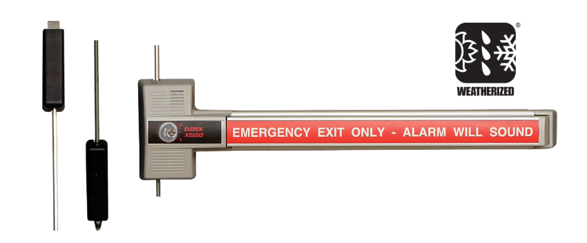
 

Detex ECL Internal Mechanism Parts

The internal mechanism is where most field failures originate on high-cycle ECL installations. The cam bridge converts lever motion into bolt retraction. The bolt assembly is the primary locking element. On installations operating several hundred cycles per day (healthcare corridors, stairwell exits), both wear before other components.


Replacement Mechanism Assembly: ECL-243PH

Detex ECL-243PH replacement mechanism assembly for ECL-230 exit control lock internal components

Detex ECL-243PH replacement mechanism assembly. View product page and order.


The ECL-243PH is the complete internal mechanism replacement for the ECL-230X and ECL-230D. It replaces the cam plate, cam bridge, detent assembly, and actuator components as a single kit. When a field diagnosis determines that multiple internal components have worn simultaneously, or when the failure mode is unclear, replacing the complete mechanism assembly is more cost-effective than sourcing individual components. This is the correct replacement for ECL-230X, ECL-230X-W, ECL-230X-TB, ECL-230X-TDB, and compatible ECL-230D configurations.


Individual Internal Components

When only one component has failed, individual replacement reduces cost and downtime. The most commonly replaced individual components are:

  • ECL-1576-15 cam bridge assembly kit: The bridge that transmits lever depression to the bolt. Fails under high-cycle use when the cam surface wears. Replace when the lever depresses but the bolt does not fully retract.
  • ECL-306-1 bolt assembly: The primary locking bolt. Replace when the bolt sticks in the engaged position or fails to return to the locked position after the delay cycle.
  • ECL-293A detent lever: Holds the bolt in the locked position until the delay cycle completes. Replace when the device fails to hold the 15-second delay and releases immediately on bar depression.
  • ECL-284 detent spring: Return spring for the detent lever. Replace when the detent lever returns sluggishly or not at all.
  • ECL-285A cam plate (bottom): Bottom cam plate in the locking assembly. Replace in conjunction with the cam bridge on multi-component failures.
  • ECL-1576-20 actuator and release lever kit: View the ECL-1576-20 product page. Replaces the actuator and release lever as a paired kit. Replace when the lever operates but the actuator does not engage the release mechanism correctly.
  • ECL-204 switch assembly: View the ECL-204 product page. The electrical switch that triggers the alarm and initiates the delay timer. Replace when the alarm does not sound on bar depression.


Bar, Paddle, and Plate Components

The bar assembly is the highest-wear external component on ECL installations, particularly in applications with repeated unauthorized attempts or high foot traffic. Sixteen bar, paddle, and plate components are stocked across standard, long, and double-door configurations.


Paddle Bar Components

Detex ECL-2109-1 long paddle bar push plate replacement for ECL-230 exit control lock

Detex ECL-2109-1 long paddle bar push plate. View product page and order.

  • ECL-2109-1 long paddle bar push plate: The extended push plate for long-bar ECL configurations. Replace when the push surface is damaged, bent, or when the bar fails to engage the mechanism consistently.
  • ECL-2109 exit bar plate: View the ECL-2109 product page. Standard exit bar plate for ECL-230X base configurations.
  • ECL-2105 long arm bar: Extended arm bar for wide-door or double-door applications.
  • ECL-332 short arm bar: Short arm bar for narrow-door or restricted-clearance applications.
  • ECL-236 bar pin: The pivot pin for the bar assembly. Replace when the bar has excessive lateral play or wobble at the pivot point.


Exit Bar Plates by Language

The ECL-8220 series provides exit bar plates with multilingual "Push Until Alarm Sounds" instructions. Plates are stocked in English (ECL-8220-1), French-Canadian (ECL-8220-7), Spanish (ECL-8220-8), Chinese (ECL-8220-6 and ECL-8220-9). Replace when the instruction text has worn or when a building's occupant language profile requires a change from the installed plate.


Strike Kits and Hardware

Strike selection determines whether the bolt engages the frame correctly on each cycle. Incorrect or worn strikes are a common cause of incomplete bolt engagement on ECL installations.

  • ECL-437K adjustable surface strike: The primary field-adjustable surface strike for ECL-230X and ECL-230D installations. Adjustable to accommodate minor frame misalignment without shimming.
  • ECL-435K adjustable strike bracket: The mounting bracket for the ECL-437K strike. Replace when the bracket is bent or when frame clearance prevents correct strike positioning.
  • ECL-439K mortise strike plate kit for ECL-230D: Mortise-style strike for ECL-230D double-door applications where a surface strike is not appropriate.


Cover, Shield, and Backplate Components

  • ECL-355 cover: The protective cover over the ECL mechanism housing. Replace when damaged or when the cover no longer seats correctly after servicing.
  • ECL-354AR back plate: The back plate that mounts the ECL to the door face. Replace when the back plate is bent or when the mounting holes are damaged.
  • ECL-419 shield: Anti-vandalism shield for the bar and mechanism housing. Install on applications with documented vandalism risk.
  • ECL-405-X cover lock key: The key for the cover lock that prevents unauthorized access to the mechanism housing. Order as the ECL-405-KIT for the complete cover lock key kit.
  • ECL-354AR back plate: Rear mounting plate for ECL body-to-door attachment.


Outside Trim and Cylinder Components

  • ECL-620 outside lever trim: The outside lever handle for ECL installations where outside entry is required. The ECL-620 provides lever-controlled outside entry without compromising the delayed egress function from inside.
  • ECL-1595 standard cylinder collar: The cylinder collar for key cylinder integration. Replace when the collar is damaged or when a cylinder is being replaced on an existing installation.
  • ECL-445K-7 keyed-alike rim cylinder: Seven-pack keyed-alike rim cylinders for installations where multiple ECL devices must be keyed to the same key.


Accessory Kits

  • ECL-2111K siren/battery conversion kit: Converts an existing ECL installation to the current siren/battery configuration. Use when replacing the alarm module or upgrading an older device to current battery specifications.
  • ECL-498K outside pull and warning sign kit: Combines an outside pull handle with a warning sign for applications where outside approach needs to communicate the delayed egress status to incoming users.
  • ECL-475K decorative back plate kit: Trim kit for architectural applications where a finished appearance is required around the ECL body.
  • ECL-2100K bar guard kit: Protective guard for the bar assembly. Install on applications with documented bar damage or vandalism risk.
  • ECL-436K panic bar plate guard kit: Guard kit for the panic bar plate. Protects the push plate instruction text from wear and damage on high-cycle installations.


Delayed Egress Door Signs: Code Requirement, Not Accessory

The ECL-395 series of delayed egress door signs is a code requirement under IBC Section 1010.2.9 and NFPA 101 Section 7.2.1.6. Both codes require that a sign be posted on the door or the adjacent wall at delayed egress devices, informing occupants that the door will open in 15 seconds when the bar is pushed and the alarm is sounding.

Failure to post the required sign is a code violation independent of whether the device itself is functioning correctly. During NFPA 80 annual fire door inspections and local AHJ inspections, missing or damaged delayed egress signs are cited as a deficiency requiring immediate correction. For annual inspection requirements, see the NFPA 80 inspection guide.


Delayed egress signs are stocked in seven language versions:

Part NumberLanguageFormat
ECL-395-1EnglishStandard delayed egress door sign
ECL-395EnglishAlternate format
ECL-395-2 / ECL-395-3French-CanadianTwo format options
ECL-395-4SpanishDelayed egress door sign
ECL-395-6 / ECL-395-7FrenchTwo format options
ECL-395-8 / ECL-395-9GermanTwo format options
ECL-395-10 / ECL-395-11ChineseTwo format options
ECL-395-12 / ECL-395-13English/EuropeanTwo format options


When to Replace vs When to Replace the Complete Device

Most field failures on ECL-230X installations can be resolved with individual or mechanism assembly replacement rather than a full device swap. The decision depends on which components have failed and the age of the installation.

  • Replace individual components when the failure is isolated to a single part (detent spring, bolt assembly, cam bridge, switch assembly) and the device is within its service life.
  • Replace the mechanism assembly (ECL-243PH) when multiple internal components have worn simultaneously or when the failure mode is ambiguous after inspecting individual parts.
  • Replace the complete device when the housing is damaged beyond cosmetic repair, when the device is more than 15 years old with no service history, when the locking configuration needs to change (single-point to 3-point), or when weatherized status is being added to a previously interior-rated installation.

For guidance on OEM versus aftermarket parts compatibility on exit control locks, see the OEM vs aftermarket commercial door hardware guide. For a broader maintenance and inspection schedule, see the commercial door hardware maintenance checklist.


Applications by Building Type

The Detex ECL is most commonly specified in the following building types. Each application has specific configuration requirements that determine which parts are needed:

Building TypeTypical ECL ApplicationConfiguration Note
HealthcareMemory care and behavioral health stairwells, elopement preventionInterior ECL-230X, high-cycle mechanism parts
Government buildingsRestricted stairwell access, utility exitsECL-600 where fire-rated; ECL-445K-7 keyed-alike cylinders
Parking garagesPedestrian exits from parking structure to streetWeatherized ECL-230X-W configurations required
Warehouses and industrialLoading dock personnel exits, restricted accessWeatherized where exposed; bar guard kit for forklift proximity
UniversitiesDormitory secondary exits, restricted building accessECL-8220 exit bar plates in multilingual buildings


Source Detex ECL Parts at Security Parts

Security Parts stocks all 59 Detex ECL parts across the ECL-230X, ECL-230D, ECL-600, and ECL-230X-W families. The catalog includes complete replacement devices, the ECL-243PH mechanism assembly kit, all individual internal components, bar and paddle assemblies, strike kits, delayed egress signs in seven languages, cylinder and trim options, and accessory kits for vandalism protection and alarm conversion.

For the full exit control lock and exit alarm parts catalog, see the exit alarms parts and diagrams guide. For broader exit device parts coverage, see the exit devices parts guide and the commercial exit device parts guide.

For life safety hardware guidance by building type, see the guides for healthcare, government buildings, parking garages, warehouses and industrial, and universities and colleges.

For access control integration with delayed egress devices, see the access control and commercial door hardware integration guide.

Same-day shipping on stocked components. Call 845-935-0301 for pre-order compatibility support on Detex ECL parts before your order is placed.


About the Author

This guide was written by the Security Parts team, a commercial door hardware specialist serving locksmiths, facilities managers, general contractors, and access control integrators since 2001. Security Parts stocks the complete Detex ECL parts catalog across all ECL-230X, ECL-230D, ECL-600, and weatherized configurations, with same-day shipping on stocked components and pre-order compatibility support at 845-935-0301.

Schlage L283 Trim Parts Guide: Lock Cases, Spring Cages, Mounting Plates, and L583 Components

Quick Answer

The Schlage L Series mortise lock uses two separate part families for replacement:

  • L283 covers the outside trim assembly: lock cases (function-specific), spring cages, spindles, mounting plates, rose trim, latchbolts, deadbolts, coin turns, electrified chassis, and VandlGard cases.
  • L583 covers the internal mortise lock body: mounting posts (by door thickness), retractor assembly, hub and spring components, fire door fuse and catch, and internal mechanism parts.
  • Lock cases are function-specific and must match your L9xxx function code exactly. Using the wrong case prevents the lock from operating.
  • VandlGard locks (LV-prefix function codes) need VandlGard-specific L283 cases and are not interchangeable with standard L283 cases.
  • L583 mounting posts must match door thickness exactly, from 1-3/4 inches to 3-1/2 inches. Ordering the wrong length is the most common parts error on L Series installations.
  • L583-748 retractor hub replaces the discontinued L583-019. Two required per lock.

Security Parts stocks all 195 L283 and L583 components. Call 845-935-0301 for pre-order compatibility support. Browse the full Schlage parts catalog or navigate directly to the mortise lock parts catalog.


What L283 and L583 Mean in the Schlage L Series

When ordering replacement parts for a Schlage L Series mortise lock, two part number prefixes appear repeatedly: L283 and L583. Understanding what each covers before searching for a part saves significant time and prevents wrong-part orders.

L283 is the Schlage designator for the outside trim assembly of the L Series. This includes everything that interacts with the user on the exterior of the door: the lock case mechanism that determines how the lever and deadbolt function, the spring cage that returns the lever, the spindle that connects the lever to the lock case, the mounting plate that secures the trim to the door face, the rose trim that covers the escutcheon hole, latchbolts, deadbolts, and coin turns.

L583 is the Schlage designator for the internal mortise lock body components. These are the parts inside the mortise case itself: the mounting posts that hold the trim to the door at the correct thickness, the retractor assembly that drives the latch, the hub and spring components, the fire door fuse and catch required on fire-rated assemblies, and the internal mechanism parts including links, springs, and cams.

When a problem appears at the outside trim level: a lever that does not return, a spring cage that is worn, a rose trim that has been damaged: the replacement comes from the L283 family. When the problem is internal to the mortise case: a latch that does not retract fully, a deadbolt that does not throw, a mechanism that binds: the replacement comes from the L583 family.

For a broader overview of the Schlage L Series mortise lock system, see the Schlage L Series mortise lock parts guide and the Schlage L Series parts and diagrams guide. For function code reference across all L9000 models, see the commercial lock function codes guide.


L283 Lock Cases: Matching the Case to the Function Code

The lock case is the single most important Schlage L283 trim part to order correctly. It determines the mechanical behavior of the lock, whether the lever is always free, key-controlled, thumbturn-controlled, or electrified. Because lock cases are function-specific, the function code stamped on the existing mortise case must be confirmed before ordering a replacement.

Schlage L283-112 basic lock case for L9000 series mortise lock L Series trim parts

Schlage L283-112 basic lock case for the L9000 series. View product page and order.


Standard L283 Mortise Lock Cases

The standard L283 lock case range covers 22 function-specific configurations. Each is matched to one or more L9xxx function codes. The most commonly replaced cases include:

Part NumberCompatible Function CodesLock Function
L283-112L9010 (passage)Passage: lever free at all times
L283-131L9010Passage with inside thumbturn
L283-133L9050, L9060, L9070, L9071Storeroom / office / entrance
L283-062L9044, L9040Classroom / security
L283-039L9076, L9077Communicating / dormitory
L283-126L9056Entrance / vestibule
L283-137L9453Storeroom with dead bolt
L283-138L9456, L9457, L9796Office with dead bolt
L283-310L9458Entrance with dead bolt
L283-139L9460, L9462, L9463, L9464Entrance / exit with dead bolt
L283-140L9465, L9466, L9473Communicating with dead bolt
L283-146L9082, L9082EUEntrance / privacy
L283-141L9412, L9480, L9485, L9486Storeroom / classroom with dead bolt
L283-750L9025Passage with dead bolt

The function code is always the correct starting point for a lock case order. Do not attempt to substitute a case from a nearby function code without confirming compatibility. The internal mechanism geometry is specific to the function, and a mismatched case will not operate the lever and latch correctly.

For the complete list of L Series function codes and their mechanical behaviors, see the commercial lock function codes guide.


VandlGard L283 Lock Cases

VandlGard is the Schlage high-security variant of the L Series, designed to resist forced entry and vandalism at the trim assembly. VandlGard locks use LV-prefix function codes: LV9050, LV9056, LV9076, LV9077, LV9080, LV9082, LV9040, LV9044, LV9453, LV9456, LV9458, LV9460, LV9462, LV9480, LV9482, LV9484, LV9485, LV9486.

VandlGard locks require VandlGard-specific L283 lock cases. These are not interchangeable with standard L283 cases even when the function code base number is the same. A standard L283 case ordered for an LV9082 installation will not fit correctly. Twelve VandlGard L283 lock cases are stocked, covering all current LV-series function code configurations.

If your lock has an LV function code, confirm the VandlGard designation before placing any L283 parts order.


LM9300 Lock Cases

The LM9300 is a Schlage small-case mortise lock within the L Series family. It uses a separate set of L283 lock cases (L283-314, L283-316, L283-614) that are not compatible with standard L Series mortise cases. The LM9300 is frequently specified for interior applications where the full L9000 case size is not required. Three LM9300-specific lock cases are stocked.


L283 Electrified Chassis Parts

Electrified L Series mortise locks use L283 electrified chassis in place of standard lock cases. The chassis integrates the electrical components that allow the lock to respond to access control signals. Twenty-six electrified chassis configurations are stocked, covering the full range of Schlage EL, EU, LV, and LM9300 electrified function combinations.

Electrified chassis are organized by function code group and monitoring option:

  • L9090 and L9092 series: Eight chassis variants covering base, RX (request-to-exit monitoring), LX (latch monitoring), RX+LX combined, and DPS (door position sensor) configurations.
  • L9091, L9093, and L9095 series: Eight chassis variants covering the same RX, LX, and DPS monitoring combinations.
  • L9492 and L9494 series: Four chassis variants for electrified entry functions with RX, LX, and DPS options.
  • L9493 and L9495 series: Four chassis variants for electrified entry with monitoring combinations.
  • LV9090, LV9092 (VandlGard electrified): Two chassis variants for the electrified VandlGard configurations.
  • LV9091, LV9093, LV9095 (VandlGard electrified): Two chassis variants.
  • LM9300 electrified (L9350/L9370/L9180): One RX module chassis, part L283-452.

For guidance on integrating the L Series electrified mortise lock into an access control system, see the access control and commercial door hardware integration guide. For a comparison of electrified mortise locks versus electric strike configurations, see the electrified mortise lock vs electric strike guide.


L283 Trim Components: Spring Cages, Spindles, Mounting Plates, and Rose Trim

Spring Cages: L283-040 and L283-341

Schlage L283-040 spring cage replacement for L Series mortise lock trim assembly

Schlage L283-040 spring cage. View product page and order.


Two spring cage options are stocked for the L Series trim assembly:

  • L283-040 spring cage: The standard spring cage for most L Series trim applications. This is the correct replacement when the lever is failing to return to the neutral position after operation, when the return spring is visibly broken or worn, or when the trim assembly is disassembled for a general overhaul.
  • L283-341 LT springcage: The low-torque version of the spring cage, specified when the installation requires reduced lever operating force. The LT springcage is used on ADA-compliant openings where operating force must stay within the 5-pound maximum requirement, or on any application where lighter lever return is specifically called for in the hardware specification.

The spring cage is one of the highest-turnover L Series trim components on high-cycle openings. On doors that operate several hundred cycles per day, the spring cage typically shows wear before other trim components. Replacing the spring cage during routine maintenance is more cost-effective than waiting for full lever failure.


Spindles and Springs

Six spindle and spring configurations are stocked for the L Series trim. The spindle connects the outside lever to the lock case mechanism. Spindle failure typically presents as a lever that turns freely without operating the latch, or a lever with excessive rotational play.

Spindle configurations include standard through-spindle options (L283-060, L283-061, L283-064) and half-dummy application spindles (L283-065). Two spindle and spring kit configurations (L283-198, L283-199) bundle the spindle with the matching return spring for a complete replacement. The correct spindle depends on the door thickness and trim configuration in the existing installation.


Mounting Plates

Schlage L283-378 outside mounting plate assembly for L Series mortise lock trim

Schlage L283-378 outside mounting plate assembly. View product page and order.


Four mounting plate configurations are stocked:

  • L283-378 outside mounting plate assembly: The primary outside mounting plate for L Series trim. Secures the outside trim to the door face and provides the base for the spindle and rose trim.
  • L283-340 outside mounting plate assembly: Alternate outside mounting plate configuration for specific L Series trim arrangements.
  • L283-031 inside lever mounting plate: The mounting plate for the inside lever assembly. Required when the inside lever is removed or when the inside trim is being refitted.
  • L283-150 mounting plate for inside rose: The mounting plate that carries the inside rose trim. Required when the inside rose is damaged or when the inside trim is being replaced on its own.


Rose Trim and Escutcheons

Four rose trim and escutcheon configurations are stocked for the L Series:

  • L283-121: Rose trim without thumbturn, for lever-only outside trim functions.
  • L283-122: Rose trim with thumbturn, for functions where the inside thumbturn controls the outside lever.
  • L283-123: L escutcheon for 1-3/4-inch doors: the full escutcheon plate for standard commercial door thicknesses.
  • L283-101: L escutcheon thru-bolts, screws, and posts for 1-3/4-inch doors: the complete fastener kit for escutcheon installation.


L283 Latchbolts, Deadbolts, and Coin Turns

Schlage L283-049 latchbolt assembly replacement part for L Series mortise lock

Schlage L283-049 latchbolt assembly. View product page and order.


Latchbolts

The L283-049 latchbolt assembly is the primary latchbolt replacement for the L Series mortise lock. It is the spring-loaded bolt that extends and retracts as the lever is operated and that holds the door in the closed position. The L283-008 and L283-006 auxiliary latchbolt assemblies provide the anti-shim deadlatch function that prevents the latchbolt from being pushed back with a credit card or shim. On ANSI A156.13 compliant mortise locks, the auxiliary latchbolt is a required safety feature.


Deadbolts

Five deadbolt configurations are stocked: L283-075, L283-676, L283-003, L283-004, and L283-099. The correct deadbolt depends on the backset and function of the specific lock. L283-075 is the standard deadbolt for most L Series mortise configurations with a deadlocking function. L283-003 and L283-004 are 2-3/4-inch backset deadbolt options. L283-099 is the small-case mortise deadbolt for L Series locks with the L4606/L4608/L4640/L4660/L4680 and L4096 functions.


Coin Turns

Fourteen coin turn configurations are stocked in seven sizes: 19mm, 23mm, 25mm, 31mm, 37mm, 43mm, and 48mm. Each size is available in two versions: standard (L283-124 series) and Torx-fastener (L283-056 series). The coin turn is the small rotary button on the inside trim that controls the deadbolt or privacy function. Coin turn size is matched to the existing installation. When replacing a coin turn, measure the existing button diameter before ordering.


L583 Mortise Lock Body Parts

Mounting Posts by Door Thickness

Seventeen L583 mounting post configurations are stocked, covering door thicknesses from 1-3/4 inches to 3-1/2 inches. Two mounting post series are available: the L583-200 series (L583-211 through L583-219) and the L583-500 series (L583-497 through L583-504). Both series cover the same door thickness range.

Door ThicknessL583-200 SeriesL583-500 Series
1-3/8"L583-211Not available
1-3/4"L583-212L583-497
2"L583-213L583-498
2-1/4"L583-214L583-499
2-1/2"L583-215L583-500
2-3/4"L583-216L583-501
3"L583-217L583-502
3-1/4"L583-218L583-503
3-1/2"L583-219L583-504

Measure the door thickness before ordering mounting posts. If the posts are too short, the trim will not seat correctly and the lever will have excessive play. If too long, the trim will not pull tight against the door face.


Retractor Assembly Components

The retractor assembly is the internal mechanism that draws the latchbolt back when the lever is operated. Eight L583 retractor components are stocked:

  • L583-748 retractor hub: Replaces the discontinued L583-019. Two required per lock. This is the most commonly replaced retractor component on older L Series installations. If the latch is slow to retract or does not fully engage the retractor, this is the first component to inspect.
  • L583-025 retractor crank: The crank that converts lever rotation into linear latch retraction force.
  • L583-022 retractor rocker: The rocker arm that transfers motion from the retractor crank to the latch.
  • L583-024 retractor link: The connecting link between the retractor rocker and the latch assembly.
  • L583-021 retractor lever: The internal lever that drives the retractor assembly.
  • L583-058 simultaneous retractor: Used on simultaneous retraction functions where both latch and deadbolt retract together.
  • L583-053 simultaneous retractor (alternate): Alternate simultaneous retraction configuration.
  • L583-020 retractor hub spacer: Spacer component within the retractor hub assembly.


Hub and Spring Components

Four hub and spring components handle the rotation of the inside and outside lever mechanisms:

  • L583-029 turn hub: The hub that transmits thumbturn rotation to the deadbolt mechanism.
  • L583-030 entrance hub: The hub for the entrance function that allows the outside lever to operate when the lock is in the unlocked state.
  • L583-035 turn hub spring: The return spring for the turn hub assembly.
  • L583-026 hub spring: The return spring for the entrance hub. Replace when the thumbturn or entrance hub fails to return to its neutral position after operation.


Fire Door Components

Two fire door components are stocked for L Series mortise locks installed on fire-rated door assemblies:

  • L583-027 fire door fuse: A heat-sensitive fusible link inside the mortise case. When exposed to fire temperatures, it releases and allows the door to latch and fully close. Required on all NFPA 80 compliant fire door assemblies using the L Series mortise lock. The fire door fuse must be inspected during annual NFPA 80 inspections and replaced if the fusible link is compromised.
  • L583-027 fire door catch: Holds the latch in the correct position during normal door operation on fire-rated assemblies. Works in conjunction with the fire door fuse to maintain fire door compliance.

For annual NFPA 80 inspection requirements covering fire door hardware including mortise locks, see the NFPA 80 inspection guide and the commercial door fire rating guide.
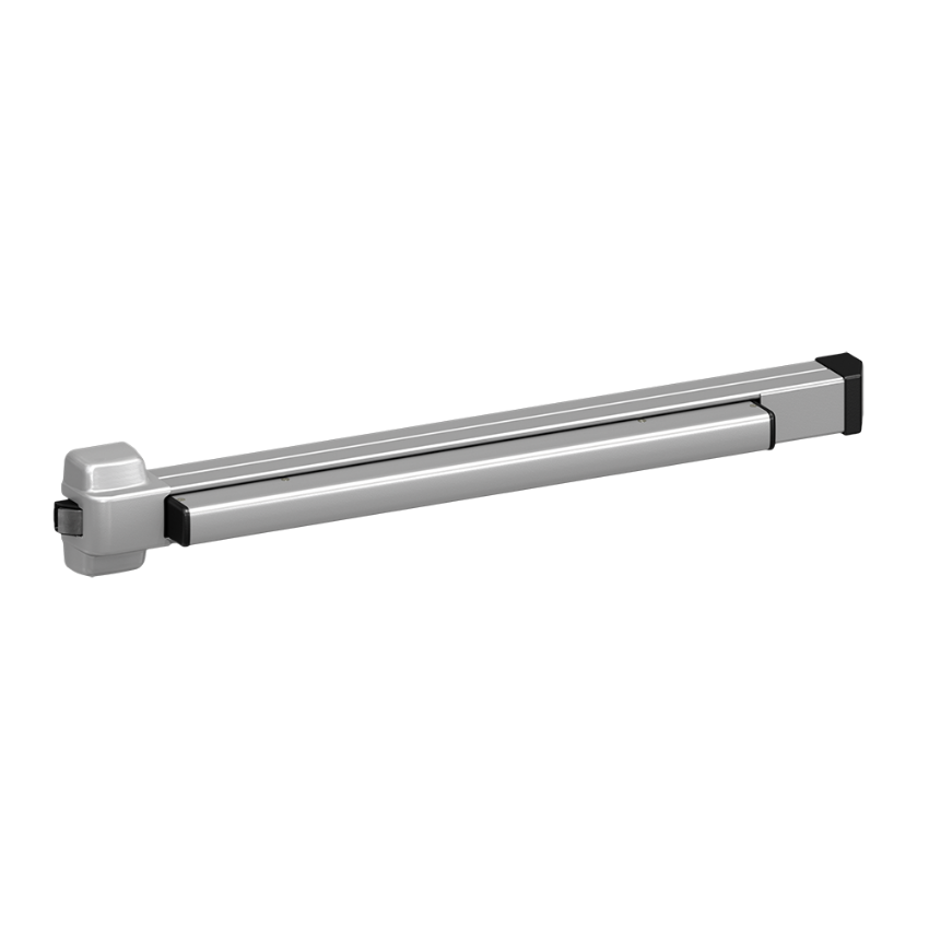
 

Additional Internal Mechanism Parts

The complete L583 internal mechanism parts catalog includes 32 additional components covering the full range of links, springs, pins, cams, catches, and guides that make up the mortise lock body. Key stocked components include:

  • L583-051 transfer lever and L583-156 transfer lifter: Transfer motion from the hub assembly to the retractor in specific function configurations.
  • L583-049 entrance link and L583-048 locking link: Link components within the entrance and locking functions.
  • L583-045 locking catch and L583-047 catch spring: Catch and spring for locking function retention.
  • L583-174 holdback dog and L583-192 dog spring: Holdback components for functions with a holdback or classroom mode.
  • L583-031 cam follower: Follower component within the cam-operated mechanism functions.
  • L583-254 L Series classic standard: The base standard configuration assembly for the L583 mortise lock body.
  • L583-004 standoff post: Standoff post for use with L Series trim configurations requiring additional door face clearance.


How to Identify the Right L283 or L583 Part Before Ordering

  1. Read the function code from the lock body. The function code is stamped or labeled on the mortise lock case: format L9xxx or LVxxx. This code determines which specific L283 lock case applies to the installation.
  2. Confirm standard, VandlGard, or electrified. Standard L Series locks use L283 part numbers. VandlGard versions use LV-prefix function codes and require VandlGard-specific L283 lock cases. Electrified locks need L283 electrified chassis with EL, EU, RX, LX, or DPS designations.
  3. Identify whether the failure is in the trim or the mechanism. Outside trim issues point to L283. Internal mechanism failures point to L583.
  4. Measure door thickness before ordering L583 mounting posts. Posts range from 1-3/8 inches to 3-1/2 inches. The wrong length causes trim misalignment and lever play.
  5. Confirm the correct retractor hub. If the lock was manufactured before the L583-019 was discontinued, the L583-748 is the current replacement. Order two per lock.
  6. Use the Security Parts L Series catalog. Part diagrams on each model page allow visual confirmation of the component before the order is placed.

For the complete Schlage L Series parts and diagrams reference, see the Schlage L Series parts and diagrams guide. For guidance on OEM versus aftermarket compatibility, see the OEM vs aftermarket commercial door hardware guide.


Source Schlage L283 Trim Parts at Security Parts

Security Parts stocks the complete Schlage L283 trim parts and L583 mortise lock body catalog: 109 L283 components and 86 L583 components across all standard, VandlGard, electrified, and LM9300 configurations. The catalog is organized by model with interactive parts diagrams on every model page, allowing visual confirmation of the component before the order is placed.

Browse the Schlage parts catalog or navigate directly to the mortise lock parts catalog. For series-specific reference across all Schlage L Series models and functions, see:

For general mortise lock reference:

Same-day shipping on stocked components. Pre-order part identification and compatibility support at 845-935-0301.


About the Author

This guide was written by the Security Parts team, a commercial door hardware specialist serving locksmiths, facilities managers, general contractors, and access control integrators since 2001. Security Parts stocks the complete Schlage L283 trim parts and L583 mortise lock body catalog across all standard, VandlGard, electrified, and LM9300 configurations, with same-day shipping on stocked components and pre-order compatibility support at 845-935-0301.

LCN 1450 Door Closer Parts Guide: Arms, Tracks, Cylinders, and Covers

Quick Answer

The LCN 1450 is a parallel arm surface door closer available in two configurations: the standard 1450 (arm-and-shoe system) and the 1450T (track arm system). Replacement parts are not interchangeable between the two. Here is what to know before ordering:

  • 1450 arms: Six types: regular (3077/62A), EDA extra duty (3077EDA), spring cushion (3077CNS/3077SCNS), PA parallel arm (3077PA), and long arm (3077L). Hold-open variants use 3049 in place of 3077.
  • 1450T tracks: Four options: 3038 standard, 3038H hold-open, 3038B bumper, 3038HB both. Track roller (3034H) and hold-open clip (3054) are the highest-wear components.
  • PA shoe (62PA) is handed : specify Left or Right when ordering. (Remove em dash replacement below) specify Left or Right when ordering. The 62A auxiliary shoe is not handed.
  • Spring cush block (3080) is replaceable without replacing the full arm.
  • Cylinders: 3071 standard, 3071DEL delay action.

Security Parts carries the complete LCN 1450 parts catalog with same-day shipping on stocked items. Call 845-935-0301 for pre-order part identification support. Browse the full LCN parts catalog or navigate directly to the LCN 1450 model page.


What the LCN 1450 Is and Where It Is Installed

LCN 1450 door closer parts guide model overview parallel arm surface closer

LCN 1450 parallel arm door closer. View model page and parts diagrams.


The LCN 1450 is a parallel arm surface door closer designed for applications where a standard arm swing would create a clearance problem. On a standard door closer, the arm sweeps outward as the door opens. On an aluminum storefront, a narrow corridor, or a door swinging into a stairwell, that arm arc can strike a wall, trim, or obstruction. The parallel arm geometry on the 1450 keeps the arm close to the door face throughout the swing, eliminating the clearance issue.

The 1450T variant uses a track arm system instead of a conventional arm-and-shoe setup. The track arm's roller travels inside a channel mounted on the door face, providing a smooth, linear closing force that many specifiers prefer on high-cycle aluminum storefront doors. The 1450 and 1450T share the same closer body but use entirely different arm and track hardware. Parts do not interchange between the two configurations.

For a broader reference on LCN door closer selection by application, see the LCN commercial door closer selection guide and the commercial door closers types guide. For sizing requirements, see the LCN door closer sizing guide.


LCN 1450 Arm System: All Types Explained

The arm system is the most frequently replaced component group on the LCN 1450. Arm selection determines the mounting geometry, the closing force distribution, and whether hold-open function is included. Every arm type is available in a standard (non-hold-open) version and a hold-open version.

The part number convention is straightforward: 3077 = standard arm (no hold-open), 3049 = hold-open arm. Add the arm type suffix and the result is the complete arm part number.


Regular Arm: 1450-307762A and 1450-304962A

The regular arm is the baseline configuration for the 1450 when the application requires a parallel arm geometry without any special closing characteristics. It pairs with the 62A auxiliary shoe. The 62A shoe is not handed and fits either side of the installation. The hold-open version is designated 1450-304962A.

LCN 1450-3077EDA extra duty arm replacement part for 1450 door closer

LCN 1450-3077EDA extra duty arm. View product page and order.


Extra Duty Arm: 1450-3077EDA and 1450-3049EDA

The EDA (extra duty arm) is a heavier-gauge arm specified for high-cycle openings, institutional applications, or any door that receives heavier-than-normal traffic. It uses the same 62A shoe as the regular arm but is built to a higher structural tolerance. On openings where regular arms are showing premature wear or bending, the EDA is the correct replacement choice. The hold-open EDA is the 1450-3049EDA.

EDA versions with the 62G shoe are also available: 1450-3077EDAG and 1450-3049EDAG.


Spring Cushion Arm: 1450-3077CNS, 1450-3077SCNS, and Hold-Open Variants

The spring cushion arm incorporates a spring cush block (3080) within the arm assembly. The spring cushion function absorbs the initial closing force, providing a gentler door pull at the beginning of the closing cycle. This is specified on doors where a hard initial pull is a problem, such as glass doors where rapid closing can cause frame stress or where ADA opening force requirements are being approached.

The 3077CNS is the standard spring cushion arm. The 3077SCNS adds a spring within the cush block for a stronger cushion effect. Hold-open versions are the 1450-3049CNS and 1450-3049SCNS respectively.

The spring cush block (1450-3080) is a replaceable component. If the cushion function has degraded but the arm structure is intact, replacing the 3080 block restores the spring cushion without requiring a full arm replacement.


PA Parallel Arm: 1450-3077PA and 1450-3049PA

The PA arm pairs with the 62PA parallel arm shoe rather than the standard 62A auxiliary shoe. The 62PA shoe is handed and must be specified as Left or Right when ordering. Confirm the handing of the existing installation before placing the order: Left is correct when the hinge is on the left side facing the pull side of the door, Right when the hinge is on the right side.

The hold-open version is the 1450-3049PA. Browse the 1450-3077PA parallel arm with 62PA shoe on the product page.


Long Arm: 1450-3077L and 1450-3049L

The long arm provides additional reach where the standard arm geometry does not produce the correct geometry relative to the door width and frame dimensions. It uses the 62A shoe and follows the same hold-open designation pattern: 1450-3049L for the hold-open version.


LCN 1450T Track System: Tracks, Rollers, and Clips

LCN 1450T-3038 standard track replacement part for 1450T door closer

LCN 1450T-3038 standard track. View product page and order.


The 1450T track system uses a single arm type (the 1450T-3077T standard arm) paired with a track assembly selected to match the required closing function. The track roller and hold-open clip are the components most subject to wear on high-cycle 1450T installations.


Track Variants: Standard, Hold-Open, Bumper, and Combined

Part NumberTrack TypeHold-OpenBumperPrimary Application
1450T-3038StandardNoNoStandard commercial, no hold-open needed
1450T-3038HHold-openYesNoOpenings requiring door to hold at 80-110 degrees
1450T-3038BBumperNoYesProtects wall or stop at full swing position
1450T-3038HBHold-open + bumperYesYesHigh-traffic, hold-open with wall protection


Wear Components: Track Roller and Hold-Open Clip

On high-cycle 1450T installations, the track roller (1450T-3034H) and hold-open clip (1450T-3054) are the first components to show wear. The track roller develops flat spots after extended cycling. The hold-open clip loses tension and fails to hold the door at the correct position. Both are replaceable without removing the closer body from the door. These components should be inspected during any scheduled maintenance visit on a 1450T installation. For a full maintenance schedule reference, see the commercial door hardware maintenance checklist.


LCN 1450 Cylinder Assemblies

LCN 1450-3071 cylinder assembly replacement part for 1450 door closer

LCN 1450-3071 cylinder assembly. View product page and order.


Two cylinder assemblies are available for the LCN 1450 and 1450T series.

Standard Cylinder: 1450-3071 and 1450T-3071

The 1450-3071 is the standard cylinder assembly for the 1450 closer body. The 1450T-3071 is the corresponding standard cylinder for the 1450T track arm variant. Both provide conventional spring-tension closing without any delayed action function. The 1450-3071 cylinder assembly is available with same-day shipping when stocked.


Delay Action Cylinder: 1450-3071DEL

The delay action cylinder holds the door at its fully open position for an adjustable interval before the closer spring begins pulling the door shut. It is specified on high-traffic openings where users need time to pass through without manually holding the door.

Common applications include loading dock entries, accessible entrances where users need extra time to clear the doorway, and healthcare corridor doors where staff frequently pass through carrying equipment. The delay interval is field-adjustable.

The 3071DEL replaces the standard 3071 cylinder directly. No other hardware changes are required when upgrading from a standard cylinder to a delay action cylinder.


Covers, Mounting Plates, and Accessory Components

Cover Options for the LCN 1450

Four cover options are available:

Part NumberCover TypeBest For
1450-72Standard slim coverMost commercial applications, clean profile
1450-72FCFull plastic coverModerate-duty protection, economy option
1450-72MCFull metal coverInstitutional, high-abuse, heavy-duty applications
1450-72ALTAlternate coverNon-standard profile or replacement fit requirements


Mounting Plates

The mounting plate connects the closer body to the door face. Four mounting plate options are available:

  • 1450-18: Standard mounting plate, most common configuration.
  • 1450-18FC: Standard mounting plate for use with full cover installation.
  • 1450-18PA: PA mounting plate for parallel arm installations.
  • 1450-18PAFC: PA mounting plate configured for use with the full cover.

Select the mounting plate that matches both the arm configuration (standard vs PA) and whether a full cover is being installed. The cover type determines which plate variant applies.


Additional Accessory Parts

Several additional components are stocked for the LCN 1450 series:

  • 1450-3080 spring cush block: Replacement cush block within the CUSH arm assembly. Replaceable without full arm disassembly. The spring cush block is the correct first replacement on any CUSH arm showing degraded cushion performance before the full arm is condemned.
  • 1450-146 pinion cap: Cap at the pinion end of the closer body. Replace if cracked, missing, or showing fluid seepage around the pinion end.
  • 1450-30 cush shoe support: Support component within the spring cushion arm assembly. Inspect when the CUSH arm shows lateral instability.
  • 1450-61 blade stop spacer: Spacer component for blade stop configurations. Required for correct stop positioning on blade stop mount applications.
  • 1450-419 flush panel adapter: Adapter for flush panel mounting applications where the door surface does not accommodate standard mounting geometry.
  • 1450-31 cover screw: Replacement cover mounting screw. Rebox kits (1450-Rebox-Kit and 1450T-Rebox-Kit) include replacement boxes and instruction sheets for models that have lost their original documentation.


How to Identify the Right LCN 1450 Part

The fastest identification path starts with the model label on the closer body, which confirms whether the closer is a 1450 or 1450T. From there, the arm or track currently installed determines which replacement parts apply.

  1. Confirm 1450 vs 1450T. Check the model label on the body. If a track channel is present on the door face and the arm runs into it, the closer is a 1450T. If a conventional arm connects to a shoe on the door frame, it is a standard 1450.
  2. Identify the arm type. On the 1450: look at the arm geometry and any markings on the arm body. The EDA arm has a heavier cross-section than the regular arm. The CUSH arm has a visible spring block at the body connection point. The PA arm attaches directly to the door face without a frame shoe. On the 1450T, the arm type is always 1450T-3077T; the variable is the track assembly.
  3. Check the shoe. If a 62A shoe is installed, the arm is a regular, EDA, or long arm. If a 62PA shoe is installed, the arm is a PA configuration. Note the handing before ordering the 62PA.
  4. Match the track (1450T only). Inspect the track channel. A notch or detent near the open position indicates a hold-open track (3038H or 3038HB). A bumper pad at the end of the channel indicates a bumper track (3038B or 3038HB). No notch or bumper: standard 3038 track.
  5. Order by part number. Use the component number from the LCN 1450 model page parts diagram to confirm the exact part number before ordering.

For help interpreting parts diagrams, see the door closer parts diagram guide. For questions about whether a component is OEM or aftermarket compatible, see the OEM vs aftermarket guide.


Source LCN 1450 Door Closer Parts at Security Parts

Security Parts carries the complete LCN 1450 parts catalog, including all arm types, the full 1450T track system, cylinders, covers, mounting plates, and accessory components. Browse the door closers parts catalog or navigate directly to the LCN 1450 model page for interactive parts diagrams organized by component.

For coverage of the full LCN door closer parts catalog across all series:

For installation and adjustment references, see the how to install a commercial door closer guide and the how to adjust a commercial door closer guide. For fire door compliance requirements relevant to closer selection, see the commercial door fire rating guide. For ANSI/BHMA grade requirements, see the ANSI/BHMA door hardware standards guide.
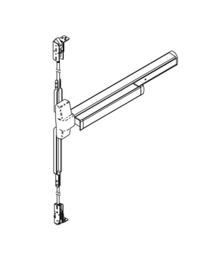
Same-day shipping is available on stocked components. Pre-order part identification support is available at 845-935-0301. For repair and replacement guidance beyond parts identification, see the commercial door hardware replacement and repair guide.


About the Author

This guide was written by the Security Parts team, a commercial door hardware specialist serving locksmiths, facilities managers, general contractors, and access control integrators since 2001. Security Parts carries the complete LCN 1450 door closer parts catalog across all arm, track, cylinder, and cover configurations, with same-day shipping on stocked components and pre-order part identification support at 845-935-0301.

How to Install an Electric Strike: Frame Prep, Wiring, and Alignment

Quick Answer

Installing an electric strike correctly comes down to four decisions made in the right order: mode first, voltage second, frame prep third, wiring fourth. Here is the short version:

  • Choose fail-safe or fail-secure before ordering. Fire-rated assemblies require fail-secure. This determines your power supply type and fire compliance path.
  • Verify voltage before connecting anything. Use a multimeter at the power supply output. Exceeding rated voltage by 10 percent damages the solenoid permanently.
  • Fire-rated frames require factory cutouts. Field-cutting a fire-rated frame voids the fire label. Specify the electric strike prep when you order the frame, not after it arrives.
  • Install the back EMF suppression diode. It protects the access control panel from voltage spikes every time the solenoid de-energizes.

Security Parts carries the full Von Duprin electric strike catalog for the 5100 Series, 6100 Series, and 6300 Series with same-day shipping on stocked components. Call 845-935-0301 for pre-installation compatibility support. For a broader reference on commercial door hardware selection, see the commercial security hardware guide.


Before You Touch the Frame: The Two Decisions That Come First

Most electric strike installation problems trace back to a decision made too late in the process. Frame cutouts, power supply specifications, and fire compliance paths all depend on two choices that need to happen before the frame is ordered and before a multimeter is picked up.


Decision 1: Fail-Safe or Fail-Secure?

Von Duprin 5100 Series electric strike installation fail-safe fail-secure field selectable commercial door

Von Duprin 5100 Series electric strikes. Browse 5100 Series models.


Fail-secure means the strike stays locked when power is cut. Fail-safe means it releases. This is the most consequential decision in the installation because it determines the power supply type, the fire rating eligibility, and the NEC compliance path.

Use fail-secure when:

  • The door is on a fire-rated assembly. Fire doors must positively latch during a power outage. Fail-safe operation on a fire door fails this requirement.
  • The door is a secured perimeter entry that must remain locked if the access control system loses power.
  • The local Authority Having Jurisdiction (AHJ) has not specifically approved fail-safe for the application.

Use fail-safe when:

  • The door is on a non-fire-rated egress path where free egress during a power outage is required by code.
  • The application is a stairwell or emergency egress corridor that must remain accessible if the system fails.
  • The access control specification explicitly calls for fail-safe and the AHJ has approved it.

Most Von Duprin 5100 and 6100 Series electric strikes ship from the factory in fail-secure mode. Field reversal to fail-safe is available on select models. For a detailed comparison of how fail-safe and fail-secure interact with fire door hardware, see the electric strikes complete guide and the commercial door fire rating guide.
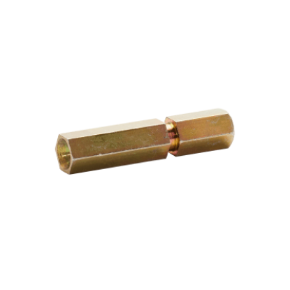
 

Decision 2: What Voltage Does the Strike Require?

Most commercial electric strikes operate on 12VDC, 24VDC, or both. Some models accept AC voltage with an external rectifier. Confirm the voltage requirement of the specific strike model before specifying the power supply. The power supply must be sized for both the inrush current (higher, momentary) and the holding current (lower, continuous) of the strike, not just the holding current shown in most marketing specs.

Voltage mismatch is the single most common cause of solenoid failure in the field. Do not rely on a power supply's label alone. Verify actual output voltage with a multimeter before connecting the strike.


Frame Preparation: Requirements by Door and Frame Type

An electric strike requires a larger frame cutout than a standard strike plate. The cutout dimensions vary by strike model and faceplate selection. The frame must also include a wire access point for routing low-voltage wiring from the back of the frame cavity to the strike location.


Hollow Metal Frames

Hollow metal frames are the most common installation type for commercial electric strikes. The standard process:

  1. Mark the strike centerline based on the latchbolt height when the door is closed.
  2. Use the cutout template included with the strike to mark the frame cutout dimensions.
  3. Cut the frame using an appropriate metal cutting tool. Verify the cut is clean and burr-free before mounting.
  4. If the frame does not have factory-installed mounting tabs, install the no-weld mounting tab kit before inserting the strike body.
  5. Confirm a wire access point exists in the frame. If not, add a wire access hole in the back of the frame channel before the strike is inserted.


Fire-Rated Frames: Factory Prep Is Mandatory

This is the most frequently violated rule in electric strike installation. The electric strike cutout in a fire-rated frame must be factory-prepared as part of the original frame fabrication order. Field-cutting a fire-rated frame voids the UL fire label on the frame, which voids the fire rating of the entire door assembly.

The factory prep requirement means the electric strike model must be selected and specified before the frame is ordered. At minimum, specify:

  • The strike model and faceplate option (which determines the cutout dimensions)
  • The wire access point location
  • The conduit knockout or channel pathway for routing low-voltage wiring

For compliance requirements on fire door assembly hardware, see the commercial door fire rating guide, the NFPA 80 inspection guide, and the ANSI/BHMA door hardware standards guide.


Wood Door Frames

Electric strikes in wood door frames use wood screws instead of mounting tabs. The frame cutout follows the same template as hollow metal, but wood frames do not require a factory prep for fire-rated applications because rated wood frames use different construction and listing requirements. Confirm fire rating status of the specific wood frame before proceeding without factory prep.


Aluminum Storefront Frames

Aluminum storefront frames require a no-weld mounting bracket kit. Standard hollow metal mounting tabs cannot be welded to aluminum. The no-weld bracket system uses adhesive shims and mechanical fasteners to secure the strike in the aluminum frame cutout. Confirm the strike model is compatible with aluminum frame installation before ordering.


Wiring the Electric Strike: Voltage, Wire Gauge, and Power Connection

Von Duprin 050034 solenoid kit 12VDC 24VDC for 5100 Series electric strike wiring installation

Von Duprin 050034 solenoid kit for 5100 Series. View product page.


Step 1: Verify Voltage at the Source Before Connecting

Before connecting any wiring to the electric strike, use a multimeter to measure actual output voltage at the power supply terminals. Power supplies and low-voltage transformers frequently operate above their stated rating. Any input voltage exceeding the strike's rated voltage by more than 10 percent permanently damages the solenoid coil. This damage is not covered under warranty and is not visible until the solenoid fails under load.


Step 2: Select the Correct Pigtail Connector for the Voltage

Von Duprin 5100 and 6100 Series strikes ship with two pigtail connectors: one marked "12 VDC" and one marked "24 VDC." Connect the pigtail that matches your power supply output, not the strike's rated voltage range.

  • For 12VAC, 12VDC, or 16VAC: use the pigtail marked 12 VDC
  • For 24VAC or 24VDC: use the pigtail marked 24 VDC

Using the wrong pigtail with the correct voltage causes the solenoid to operate outside its optimized current range. Over time, this shortens solenoid life even if the strike appears to function normally.


Step 3: Wire Gauge Requirements by Run Length

Wire gauge requirements vary by run length from the power supply to the strike location. Undersized wire causes voltage drop that reduces the strike's holding force and can cause intermittent release failures.

Run Length12VDC Minimum Gauge24VDC Minimum Gauge
Up to 200 feet18 AWG20 AWG
200 to 300 feet16 AWG18 AWG
300 to 400 feet14 AWG16 AWG

All electric strike wiring installation must comply with NFPA 70 (National Electrical Code). Maintain required separation between low-voltage access control wiring and high-voltage electrical circuits. Terminate all connections inside the frame cavity or junction box, not in the wall cavity where connections cannot be accessed later.


Step 4: AC Power and the Rectifier Requirement

An electric strike connected to an AC power supply without a rectifier will buzz continuously. AC alternates direction at 60Hz, causing the solenoid to cycle at that frequency. The buzzing is not just a nuisance: it accelerates solenoid wear and is audible to occupants.

Install an AC rectifier between the AC transformer and the strike whenever the power source is AC. The rectifier converts AC to DC at the strike, eliminating the buzzing. For wiring diagrams covering the AC rectifier connection and latchbolt monitor wiring, see the electric strike schematic diagram guide.


Step 5: Install the Back EMF Suppression Diode

When the electric strike solenoid de-energizes (when power is cut to release or lock the strike), it generates a voltage spike called back EMF. This spike travels back through the wiring to the access control panel's output relay and degrades the relay contacts over time, eventually causing intermittent failures in the access control system.

Install a back EMF suppression diode across the strike terminals, observing polarity (cathode toward the positive terminal on DC-powered models). For AC-powered strikes, use a metal oxide varistor (MOV) instead of a diode. MOVs are not polarity sensitive. Some Von Duprin strike models include the suppression component. If not included, it is available as an accessory in the parts catalog.

For a full reference on access control wiring and signal protection, see the access control integration guide.


Installing the Strike in the Frame

Von Duprin PKGMTG1004 mounting package for 5100 Series electric strike installation

Von Duprin PKGMTG1004 mounting package for 5100 Series. View product page.


Select the Correct Faceplate First

The faceplate is not a cosmetic choice. It determines which lock type the strike is compatible with (cylindrical, mortise, or exit device) and which frame cutout template applies. Selecting the wrong faceplate produces a strike that physically fits the frame but does not properly engage the latch, which causes release failures and return damage.

Von Duprin 5100 and 6100 Series faceplate options cover:

  • Standard cylindrical latchbolts
  • Mortise latchbolts with and without deadlatches
  • Exit device latches (narrow and wide configurations)
  • Hookbolt configurations for non-latchbolt applications

Select the faceplate based on the latch type and backset of the lock installed on the door. For parts reference by strike model, see the electric strike parts guide.


Route Wiring Before Inserting the Strike

Route all wiring through the frame channel and leave a sufficient service loop at the strike location before the strike body goes into the frame. Once the strike is mounted, access to the wiring connection point is limited. Pinched wiring between the strike body and the frame is a common installation defect that causes intermittent failures weeks after installation.


Mount the Strike and Confirm Alignment

  1. Insert the strike body into the frame cutout with all wiring routed clear of the strike housing.
  2. Secure using the mounting tabs and provided screws. On hollow metal frames with factory-installed tabs, thread the screws into the tabs finger-tight first.
  3. Close the door and verify the latchbolt enters the keeper cleanly without resistance. Resistance indicates a misaligned centerline.
  4. Tighten the mounting screws fully once alignment is confirmed.


Post-Installation Alignment Adjustments

Horizontal Alignment

If the latchbolt binds or does not retract cleanly when the strike is energized, horizontal alignment is the first adjustment to make. Loosen the mounting screws slightly, shift the strike body horizontally behind the faceplate until latch engagement and release are smooth, then retighten. Most Von Duprin 5100 and 6100 Series strikes allow approximately 1/8-inch horizontal adjustment within the faceplate slot.

For excessive horizontal issues where the 1/8-inch adjustment is not sufficient, remove the shim filler bar from the keeper. This increases the keeper travel range to compensate for larger frame or door alignment problems.


Vertical Alignment (For Strikes With Internal Ramps)

The internal ramps in Von Duprin 6100 Series strikes must be aligned so the deadlatch passes between the two ramps without contacting either ramp. If the deadlatch contacts a ramp, the door will not latch properly when the strike is in the locked state.

  1. Mark the centerline of the deadlatch on the strike faceplate with the door closed.
  2. Remove the strike from the frame.
  3. Loosen the internal ramp screws and slide the ramp assembly until the groove between the ramps aligns with the mark.
  4. Retighten all screws, reinstall the strike, and verify alignment by closing the door.


Testing the Electric Strike After Installation

Von Duprin 6100 Series electric strike installation testing 12VDC 24VDC commercial door

Von Duprin 6100 Series electric strikes. Browse 6100 Series models.


Every electric strike installation requires testing in both the powered and unpowered states before the door is commissioned. Do not skip the unpowered test, especially on fire-rated assemblies.


Powered State Test

  • Apply power to the strike at the rated voltage.
  • Send an unlock signal from the access control panel or apply power directly to the strike terminals.
  • Confirm the keeper retracts and the latchbolt releases cleanly when the door is pulled.
  • Confirm the keeper returns to the locked position after the door closes and the latch re-engages.


Unpowered State Test (Fail-Secure or Fail-Safe Verification)

  • Fail-secure: Disconnect power to the strike. The door should remain locked. Confirm the latchbolt cannot retract manually when the strike is unpowered.
  • Fail-safe: Disconnect power to the strike. The door should open freely. Confirm there is no resistance on the latchbolt retraction.


Fire-Rated Assembly Final Check

On fire-rated door assemblies, perform one final check in both power states: release the door from the open position and confirm it self-closes and positively latches every time. The door must latch without manual assistance in both the powered and unpowered states. If the door fails to latch in either state, the assembly is not compliant and must be adjusted before sign-off.

For ongoing maintenance requirements after installation, including NFPA 80 annual inspection procedures, see the commercial door hardware maintenance checklist.


Common Electric Strike Installation Problems and Fixes

ProblemLikely CauseFix
Strike will not releaseNo power at the strike terminals; wrong pigtail connectorVerify voltage at strike terminals with multimeter; confirm correct pigtail is connected
Strike buzzing continuouslyAC power supply connected without rectifier; incorrect polarity on DC modelInstall AC rectifier; verify polarity if DC-powered
Latchbolt does not fully engage when lockedHorizontal misalignment; backpressure from door bindingAdjust horizontal alignment; check door-to-frame gap (minimum 1/8 inch)
Solenoid has burnt smell after installationIncorrect voltage; wrong pigtail connector for voltageReplace solenoid; verify power supply voltage output with multimeter before reconnecting
Access control panel intermittent failuresNo back EMF diode installed; relay contact degradationInstall suppression diode or MOV across strike terminals
Door fails to latch when strike is lockedVertical misalignment; deadlatch contacting internal rampRealign internal ramps using deadlatch centerline mark procedure


Sourcing Von Duprin Electric Strike Parts at Security Parts

Security Parts stocks the complete Von Duprin electric strike catalog for the 5100, 6100, and 6300 Series, including replacement solenoids, faceplate options, mounting packages, and accessory kits. Browse the complete electric strikes catalog or by series:

For access control integration design including REX switch placement, door position switch wiring, and latchbolt monitor connections, see the access control integration guide. For the choice between an electric strike and an electrified mortise lock for a specific opening, see the electrified mortise lock vs electric strike guide.

Same-day shipping is available on stocked components. Pre-installation compatibility support is available at 845-935-0301. For a parallel guide on mechanical door hardware installation, see how to install a commercial door closer.


About the Author

This guide was written by the Security Parts team, a commercial door hardware specialist serving locksmiths, facilities managers, general contractors, and access control integrators since 2001. Security Parts stocks the complete Von Duprin electric strike catalog for the 5100, 6100, and 6300 Series with same-day shipping on stocked components and pre-installation support at 845-935-0301.

LCN 4040XP Parts Guide: Arms, Tracks, Shoes and Replacement Components

Quick Answer

The LCN 4040XP uses a fixed shoe arm system. The 4040XPT uses a rolling track arm system. Parts are not interchangeable between the two. Before ordering any LCN 4040XP parts, confirm four things:

  • Model variant: 4040XP (arm and shoe) or 4040XPT (track and track arm). The two share the same closer body but use completely different arm hardware.
  • Arm type: Regular, EDA (Extra Duty), CUSH (spring cushion), or PA (parallel arm). Each is a different part number and serves a different application.
  • Hold-open or standard: Hold-open arms lock the door at the open position. Standard arms close freely from any point. The part number suffix distinguishes them.
  • Arm length: Standard, long (L), or extra long (XL), determined by the door reveal depth.

Security Parts stocks the full 4040XP and 4040XPT parts catalog with same-day shipping on stocked items. Browse the LCN 4040XP model page and the 4040XPT model page for the complete parts list. Call 845-935-0301 for pre-order compatibility support.


What the LCN 4040XP Is and Why the Arm System Matters for Parts

The LCN 4040XP SuperSmoothee is the institutional benchmark Grade 1 surface-mounted door closer from Allegion. It is the most widely installed heavy-duty commercial closer in the US market, specified across hospitals, universities, government buildings, and K-12 schools. When a 4040XP arm fails, the part number depends entirely on which arm configuration was originally installed. Ordering the wrong arm type is the most common sourcing mistake on this product.

The 4040XP uses a cast iron cylinder body with a four-function hydraulic valve, Fast Power Adjust spring power control, and Liquid-X all-weather hydraulic fluid. It carries Grade 1 ANSI/BHMA A156.4 certification and meets Buy American Act (BAA) requirements for government projects. All of that institutional hardware lives in the closer body, which rarely fails. What fails is the arm assembly, the shoe, or on track versions, the track and roller.

For a reference on installing and adjusting the 4040XP after arm replacement, see the LCN 4040XP installation template guide and the commercial door closer adjustment guide.


4040XP vs 4040XPT: Two Different Parts Systems

The 4040XP uses a fixed shoe mounted on the door frame. The arm connects the closer spindle to that shoe and drives the door through its arc. The 4040XPT replaces the shoe with an aluminum track, and the arm rides inside the track on a roller throughout the door's travel. The closer body is the same on both. Everything else (the arm, the shoe or track, the roller, the hardware) is different.

If the existing installation has a channel mounted horizontally on the frame with the arm riding inside it, the unit is a 4040XPT. If the existing installation has a fixed plate on the frame with a rod-and-shoe connecting to the arm tip, the unit is a 4040XP. Confirming this before ordering prevents the most common return on this product line.


LCN 4040XP Arm Types and Part Numbers

The 4040XP arm system organizes into four main arm families. Within each family, the arm is available in standard (no hold-open) and hold-open (HO) variants. Hold-open arms add a friction mechanism at the shoe that locks the door open at a user-set position when the door is pushed past approximately 70 degrees. Standard arms allow the closer to pull the door closed from any open position without locking.


Regular Arm

The regular arm is the standard 4040XP arm for pull-side and top jamb mounting with shallow reveal. It connects the closer spindle to the rod and shoe on the door frame. Available configurations:

  • 4040XP-3077 / 3077PA: Standard regular arm. Non-handed. Mounts pull side or top jamb. The 3077PA variant includes the 62PA parallel arm shoe for parallel mounting.
  • 4040XP-3077/62A: Regular arm with auxiliary shoe pre-installed. Saves ordering the 62A shoe separately when that configuration is required.
  • 4040XP-3077L: Long arm for deeper reveals. Order the 4040XP-3077L long arm when the standard rod and shoe does not reach the frame shoe mount.
  • 4040XP-3077XL: Extra long arm for the deepest reveal situations. Order the 4040XP-3077XL extra long arm when both standard and long arms fall short.

Hold-open variants for the regular arm: 4040XP-3049PA (with 62PA shoe), 4040XP-3049/PA, and 4040XP-3049L (long hold-open arm). The 4040XP-3049L hold-open long arm is the correct part for deep-reveal hold-open configurations.


EDA Arm (Extra Duty Arm)

LCN 4040XP-3077EDA extra duty arm replacement part for heavy duty commercial door closer

LCN 4040XP-3077EDA Extra Duty Arm. View product page and order.


The EDA (Extra Duty Arm) uses heavier stamped steel construction than the standard regular arm. It is specified for high-abuse applications where standard arms fail prematurely: institutional buildings, behavioral health facilities, high-traffic hospital corridors, and correctional environments. The EDA arm has a wider pivot design and higher cycle rating than the standard arm.

  • 4040XP-3077EDA: Standard EDA arm, no hold-open.
  • 4040XP-3049EDA: Hold-open EDA arm. Holds door open at set position.
  • 4040XP-3077EDA/G: EDA arm with 62G shoe pre-installed for 180-degree swing applications.

The EDA arm is non-handed and mounts pull side or top jamb with shallow reveal, the same as the regular arm. If the existing arm is marked "EDA" or shows the heavier stamped construction, order the EDA replacement rather than the standard arm.


CUSH Arm (Spring Cushion Arm)

LCN 4040XP-3077CNS cush arm with spring cushion for 4040XP door closer

LCN 4040XP-3077CNS Cush Arm. View product page and order.


The CUSH arm adds a spring-loaded contact block at the shoe end that absorbs impact energy when the door reaches its maximum open position. It is used on doors that frequently bang into stops or walls, where the impact shortens the life of the arm, the shoe, and the door frame hardware. The spring cushion absorbs and dissipates that impact energy before it reaches the frame.

The spring cush block assembly (4040XP-3080) is the primary wear component in the CUSH system. Order the 4040XP-3080 spring cush block assembly as a standalone replacement when the cushion block has worn but the arm itself is still functional. The cush shoe support (4040XP-30) and blade stop spacer (4040XP-61) are required accessories for CUSH installations on doors with 1/2-inch blade stops.


Parallel Arm Mounting and the PA Shoe

LCN 4040XP-62PA parallel arm shoe for parallel mounting configuration

LCN 4040XP-62PA Parallel Arm Shoe. View product page and order.


Parallel arm mounting places the closer on the push side of the door with the arm running along the door face. The frame-mounted shoe (62PA) is on the push side of the frame. This configuration is used when pull-side clearance is insufficient or when the door specification requires a push-side installation.

The 4040XP-62PA parallel arm shoe is a handed component. It must be specified for the correct door swing direction. The 62PA is included with PA arm packages (3077PA, 3049PA) and is available separately for replacement.

The auxiliary shoe (4040XP-62A) serves a different purpose: it provides an additional contact point on the frame for specific arm geometries. The 4040XP-62A auxiliary shoe is included pre-installed on the 3077/62A arm package and is available separately.


LCN 4040XP Rod and Shoe: Selecting the Right Length

The rod and shoe connects the main arm to the frame shoe and is the component most directly affected by door reveal depth. Reveal depth is the distance from the door face to the inside edge of the frame stop. Ordering the wrong rod and shoe length results in an arm that either cannot fully close the door or sits at an incorrect operating angle.

Part NumberDescriptionApproximate Reveal Range
4040XP-79Standard rod and shoeUp to 3-1/4 inches
4040XP-79LRLong rod and shoe (8-3/8 in.)Up to 5-3/4 inches
4040XP-79ELRExtra long rod and shoeDeeper reveals beyond 79LR range

Arm length (3077, 3077L, 3077XL) and rod-and-shoe length work together. A long arm (3077L) typically pairs with the long rod and shoe (79LR). An extra long arm (3077XL) typically pairs with the extra long rod and shoe (79ELR). Refer to the LCN 4040XP installation diagram, available on the 4040XP diagram page to confirm the correct combination for the specific reveal depth and mounting configuration.


LCN 4040XP Cylinder Assembly and Internal Components

The 4040XP uses a cast iron cylinder assembly (4040XP-3071) that is heavier duty than the standard 4000 Series cylinder. The cast iron construction distinguishes it from the lighter 4050A and 4030 Series cylinders and is part of why the 4040XP is the institutional specification standard rather than the lighter commercial alternatives.

The 4040XP-3071 cast iron cylinder assembly is available as a complete replacement when the internal hydraulic components have failed and the closer body needs to be rebuilt rather than replaced. The arm screw (4040XP-83H) secures the arm to the closer spindle and is a common replacement on doors where the arm has been removed multiple times.


LCN 4040XPT Track Parts

The 4040XPT track system replaces the fixed shoe with an aluminum track mounted horizontally on the frame. The arm connects to a rolling carriage that travels inside the track throughout the door's travel arc, which allows the door to open to a wider range of positions without the arm reaching mechanical limits.


Track Selection for the 4040XPT

LCN 4040XPT-3038 standard track for 4040XP through-bolt track closer

LCN 4040XPT-3038 Standard Track. View product page and order.


Four track configurations are available for the 4040XPT. The suffix indicates the features:

  • 4040XPT-3038: Standard track, no hold-open, no bumper.
  • 4040XPT-3038H: Track with hold-open. The track roller locks the door in the open position when pushed past the hold-open engagement point.
  • 4040XPT-3038B: Track with bumper. Adds a cushioned end-stop at the full-open position.
  • 4040XPT-3038HB: Track with hold-open and bumper. Combines both features.


Track Arm and Track Rollers for the 4040XPT

LCN 4040XPT-3077T standard track arm for 4040XPT track door closer

LCN 4040XPT-3077T Standard Track Arm. View product page and order.


The track arm (4040XPT-3077T) connects the closer spindle to the track roller carriage. It is handed and must be specified for the correct door swing. The 4040XPT-3077T standard track arm is the most commonly replaced component on the XPT system after the track itself.

Track rollers are the wear component that fails most frequently in high-cycle track installations:

  • 4040XPT-3034: Standard track roller. Replaces a worn or seized roller without replacing the full track.
  • 4040XPT-3034H: Hold-open track roller. Required on hold-open track configurations (3038H, 3038HB) to maintain the hold-open function.
  • 4040XPT-3054: Hold-open clip. Secondary hold-open component that works with the 3034H roller.
  • 4040XPT-425: Roller lock screw. Secures the track roller to the arm carriage. Replace when the roller shows lateral movement in the track.


LCN 4040XPT Track Parts Reference Table

Part NumberDescriptionNotes
4040XPT-3038Standard trackNo hold-open, no bumper
4040XPT-3038HTrack with hold-openLocks door open at set position
4040XPT-3038BTrack with bumperCushioned end-stop at full open
4040XPT-3038HBTrack with hold-open and bumperBoth features combined
4040XPT-3077TStandard track armHanded; most common replacement
4040XPT-3034Standard track rollerWear component; replace without full track
4040XPT-3034HHold-open track rollerRequired on 3038H and 3038HB tracks
4040XPT-3054Hold-open clipWorks with 3034H roller
4040XPT-425Roller lock screwSecures roller to arm carriage


LCN 4040XP Parts Reference Table

Part NumberDescriptionNotes
4040XP-3077EDAEDA arm, standardHeavy-duty, non-handed
4040XP-3049EDAEDA arm, hold-openHeavy-duty, with HO friction
4040XP-3077CNSCUSH arm, standardSpring cushion at shoe end
4040XP-3049CNSCUSH arm, hold-openHold-open with cushion
4040XP-3077SCNSSpring CUSH arm, standardHeavier spring for harder impacts
4040XP-3049SCNSSpring CUSH arm, hold-openHeavy spring with HO function
4040XP-3077PARegular arm with 62PA shoeFor parallel arm mounting; handed
4040XP-3049PAHold-open arm with 62PA shoeParallel arm, hold-open; handed
4040XP-3077LLong armDeeper reveals; pairs with 79LR
4040XP-3077XLExtra long armDeepest reveals; pairs with 79ELR
4040XP-62PAParallel arm shoeHanded; for parallel arm only
4040XP-62AAuxiliary shoeFor 3077/62A arm geometry
4040XP-79Standard rod and shoeReveals up to 3-1/4 in.
4040XP-79LRLong rod and shoe8-3/8 in.; reveals to 5-3/4 in.
4040XP-79ELRExtra long rod and shoeDeepest reveals
4040XP-3071Cast iron cylinder assemblyHeavy duty; 4040XP specific
4040XP-3080Spring cush block assemblyWear component for CUSH arms
4040XP-83HH arm screwSecures arm to closer spindle


Where LCN 4040XP Parts Are Sourced at Security Parts

Security Parts stocks the full LCN 4040XP and 4040XPT parts catalog. The LCN 4040XP model page lists all available 4040XP arm and hardware parts by category. The 4040XPT model page covers the full track system catalog. Interactive diagrams are available on the 4040XP diagram pages for visual part identification before placing an order.

The 4040XP is specified across the most demanding commercial applications: healthcare facilities where the closer faces thousands of daily cycles, government buildings requiring BAA compliance, and universities where institutional durability is the primary specification driver. For the hardware context of those applications, see the healthcare door hardware guide, the government buildings guide, and the Division 8 specification guide.

For broader LCN door closer selection across the full 4000 Series and 2210 concealed closer, see the LCN 4000 Series and 2210 parts guide and the LCN commercial door closer selection guide. For fire door closer compliance including NFPA 80 inspection requirements, see the fire door closer adjustment guide and the commercial door fire rating guide.
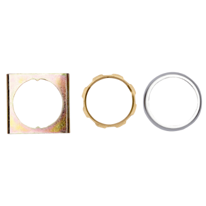
Same-day shipping is available on stocked 4040XP components. Call 845-935-0301 for pre-order compatibility support when the arm configuration or reveal dimension needs verification before the order ships.


About the Author

This guide was written by the Security Parts team, a commercial door hardware specialist serving locksmiths, facilities managers, general contractors, and access control integrators since 2001. Security Parts stocks the full LCN 4040XP and 4040XPT replacement parts catalog with same-day shipping on stocked components and pre-order compatibility support at 845-935-0301.

LCN 8310 Series Parts Guide: Actuators, Sensors and Accessories for Automatic Door Operators

Quick Answer

The LCN 8310 Series is the complete line of actuators, sensors, switches, relays, wireless kits, and accessories for LCN automatic door operators. The series works with the Senior Swing 9500/2800 and IQ series, the Benchmark 9130/9140/9150, and the Auto Equalizer 4630/4640. Three things to know before ordering:

  • Actuator type: Touchless (hand-wave) actuators come in standard IP54, stainless steel IP65 for high-abuse, and battery-powered wireless versions. Pick based on environment and wiring access.
  • Switches: The 8310-806R (rocker) and 8310-806K (key) are three-position On/Off/Hold Open switches. The 806K restricts mode changes to keyed personnel only.
  • Safety packages vs individual parts: Pre-kitted packages (8310-3883 for single door, 8310-3891 for simultaneous pair) include all sensors and relay components for a complete installation. Individual parts are available for single-component replacement.

Security Parts stocks the full LCN 8310 Series parts catalog with same-day shipping on stocked components. Call 845-935-0301 for pre-order compatibility support.


What the LCN 8310 Series Does

Every LCN automatic door operator needs two things to function as an accessible commercial entry: something to tell it when to open, and something to detect obstructions while it moves. The LCN 8310 Series provides both, plus the switches, relays, harnesses, and wireless accessories that complete the full installation.

The 8310 Series is not a standalone door operator. It is the activation and safety layer that connects to LCN's automatic operator lines, primarily the Senior Swing, Benchmark, and Auto Equalizer series. When one of those operators behaves incorrectly, or when a new installation requires activation hardware, the 8310 Series catalog is where the parts come from.

The full 8310 product family divides into six functional categories, each covered in this guide:

  • Touchless actuators (hand-wave, push-plate, and wireless)
  • Safety sensors (door mount, header mount, and sensor packages)
  • Operator control switches (rocker and key)
  • Relay modules and door sequencers
  • Wiring harnesses and accessories
  • Wireless conversion kits and remote transmitters

For the LCN automatic door operator lines that these accessories connect to, see the LCN Benchmark and Senior Swing automatic door operator parts guide, the LCN Senior Swing IQ parts guide, and the commercial door operators guide.


LCN 8310 Series Operator Compatibility

The 8310 Series is compatible with the following LCN automatic door operator families:

Operator FamilyModels8310 Compatibility
Senior Swing (9500/2800)9500, 9530, 9540, 9550, 9560, 2810, 2850, 2860Full compatibility: all 8310 accessories apply; Senior Swing-specific packages available
Benchmark (9130/9140/9150)9130 (pull side), 9140 (push side), 9150 (top jamb, double door)Full compatibility: all 8310 switches, sensors, actuators, and relay modules apply
Auto Equalizer (4630/4640)4630, 4640 (with CS option)8310-806R and 8310-806K switches apply when CS option is specified
Pneumatic operators (7900 series control box)2610, 4810, 4820, 48408310-3888 safety module harness and 8310-3889 safety module kit apply

When using 8310 actuators supplied by third parties (card readers, fob readers, PIN pads) to confirm compatibility with the operator's actuation input before ordering. Most 8310 actuators provide normally open dry contacts, which is the standard input requirement for LCN automatic operators. For access control integration specifics, see the access control integration guide.


LCN 8310 Touchless Actuators: Selecting the Right Type

Touchless actuators are the most frequently replaced component in the 8310 Series. They detect hand movement using microwave motion sensing and send a dry contact signal to the operator's activation input. No physical contact with a push plate, door handle, or exit bar is required, which is the primary reason they are specified on accessible commercial entries, healthcare corridors, and infection-control environments.

The 8310 touchless actuator line is organized by form factor, environment rating, and wiring type. Choosing the wrong variant is the most common ordering error.


Standard Touchless Actuators (8310-813 Series)

The 8310-813 is the standard medium-duty touchless actuator, rated IP54 for protection against dust and water splashing from any direction. It uses microwave motion sensing at 24.125 GHz with an adjustable detection range of 4 to 24 inches. Operating voltage is 12 to 24 VAC/DC. Available in multiple form factors:

  • 8310-813: Single and double gang, black, wave icon and text
  • 8310-813J: Jamb mount, black, wave icon and text
  • 8310-813R: Round, black, wave icon and text
  • 8310-813WH / 813JWH / 813RWH: White versions of the above

The 8310-810 series covers heavy-duty stainless steel versions in single gang (810S), double gang (810D), and round (810R) formats, with accessibility (wheelchair) icon options available on the 810SA, 810DA, and 810RA variants.


High-Abuse and Harsh Environment Actuators (8310-815)

The 8310-815 is rated IP65 and NEMA 4, making it appropriate for exterior installations, high-abuse institutional environments, and facilities exposed to cleaning chemicals or pressure washing. The IP65 rating means the actuator is fully dust-tight and protected against directed water jets, a significant step up from the IP54 standard rating. It uses the same microwave detection technology as the 813 series but in a sealed stainless steel enclosure.


Battery-Powered and Wireless Actuators

Battery-powered touchless actuators eliminate the need to run low-voltage wiring to the actuation point. The 8310-2210 is a pre-kitted package that includes all necessary RF hardware pre-programmed. Individual battery-powered faceplate options in the 8310-2310, 2320, 2330, and 2340 are AA-battery-powered and compatible with existing LCN transmitters and receivers.

Wall-mount and jamb-mount wireless actuator packages in the 8310-38xx series include all mounting hardware and can be specified in surface (WS suffix) or flush (WF suffix) mounting configurations. The bollard-mounted wireless actuator (8310-3853TWB) is available for exterior installations where wall mounting is not practical.


LCN 8310 Operator Control Switches

LCN 8310-806R rocker switch three-position on off hold open for automatic door operators

LCN 8310-806R rocker switch. View product page and order.

The LCN 8310-806R and 8310-806K are three-position control switches used with Senior Swing, Benchmark, and 4630/4640 operators that include the Control Switch (CS) option. Both switches provide the same three positions: Off, Auto, and Hold Open.

  • 8310-806R Rocker Switch: Toggle-action switch. Suitable for facility management applications where trained staff control the door mode throughout the day. The rocker action makes the current position visually identifiable at a glance.
  • 8310-806K Key Switch: Key-operated switch. Restricts mode changes to personnel with the appropriate key. Specified on applications where unauthorized mode switching (such as leaving the door in Hold Open in a secure area) is a security risk.

LCN 8310-806K key switch three-position for Senior Swing Benchmark and Auto Equalizer operators

LCN 8310-806K key switch. View product page and order.

A note on switch installation: The 8310-806K and 8310-806R are optional accessories, and not all operator installations include them. On operators with the CS option, the switch allows management of door mode at the entry point without requiring access to the operator's control box. On installations without the CS option, mode adjustments are made at the control box directly.


LCN 8310-845 Relay and Door Sequencer

LCN 8310-845 programmable relay and door sequencer for automatic door operator wiring

LCN 8310-845 relay and door sequencer. View product page and order.


The 8310-845 programmable relay module sequences door operation in Senior Swing and Benchmark operators for hardwired applications. It is the component that coordinates the timing relationship between the activation signal, the door motion, and the safety sensors.

The 8310-845 is specifically required when the door mount safety sensor (8310-804-1 or 8310-804-2) is installed in conjunction with the door position switch (8310-805 or 8310-805C) on electrohydraulic, pneumatic, or Benchmark operators. The relay module ensures the approach-side sensor is disabled when the door is in the closed position, preventing false activation from pedestrian traffic passing near a closed door.

If a door is cycling erratically, activating when no pedestrian is present, or failing to hold open correctly after the activation sensor triggers, the 8310-845 is the first relay component to inspect. The 8310-845 is also included in the 8310-3883 Senior Swing Single Door Package and the 8310-3878/3879 safety packages.


LCN 8310 Door Position Switches

LCN 8310-805 door position switch surface mount for automatic operator approach sensor disabling

LCN 8310-805 door position switch. View product page and order.


Two door position switch variants are available:

  • 8310-805: Surface mount. Mounts on the frame or door surface. Used when a concealed installation is not required or not possible.
  • 8310-805C: Concealed mount. Preferred for interior applications where the switch should not be visible. Included in the 8310-3883 Senior Swing Single Door Package.

Both switches work with the door mount safety sensors (8310-804-1 or 8310-804-2) and the 8310-845 relay module. The switch changes state when the door reaches the fully closed position, telling the relay to disable the approach-side sensor. Without it, an activation sensor facing a high-traffic corridor will trigger the door to open every time someone walks past, even when no one intends to enter.


LCN 8310 Safety Sensors and Sensor Packages

The LCN 8310 Series includes two categories of safety sensors: header mount sensors that detect objects approaching or in the door's path, and door mount sensors that detect obstructions on the leading edge or full face of the door during the open and close cycle.


Header Mount Safety Sensor (8310-877)

The 8310-877 header mount safety sensor uses diffused infrared technology to detect obstructions during the door's open and close positions. It has nine selectable detection patterns, programmed using the 8310-859 handheld remote control. The 8310-877S spacer is a required accessory when the 8310-877 is used with the 8310-804-1 or 8310-804-2 door mount sensors on Senior Swing installations. The 8310-846 header mount harness is included with the 8310-877.


Door Mount Safety Sensors

Two door mount sensor configurations are available:

  • 8310-804-1: Contains one active sensor module. Detects obstructions on the leading edge of the door. Lighter-duty installations where only the door edge needs monitoring.
  • 8310-804-2: Contains two active sensor modules. Detects obstructions across the full face of the door. Specified for high-traffic applications and code-compliant installations where ANSI A156.10 pedestrian door safety requirements apply.


Pre-Kitted Safety Sensor Packages

For complete new installations, pre-kitted sensor packages eliminate the risk of ordering individual components that do not work together. All packages include the necessary sensors, harnesses, and spacers:

PackageApplicationKey Contents
8310-3881Single door, full sensor coverage8310-854 (x2), 8310-877, 8310-877S, 8310-804-2
8310-3882Double door, full sensor coverage (not double egress)8310-854 (x2), 8310-877, 8310-877S, 8310-847 (x2), 8310-804-2 (x2)
8310-3883Senior Swing single door, low-energy convenience8310-804-1, 8310-805C, 8310-845
8310-3891Senior Swing simultaneous pair (Healthcare I)8310-877, 8310-877S, 8310-804-2 (x4), 8310-847 (x2)
8310-3892Senior Swing independent pairFull sensor package for independent pair door configuration
8310-3888 / 3889Pneumatic control box (7901, 7902, 7981, 7982)Safety module harness (3888) and safety module kit (3889) for pneumatic operators


LCN 8310 Wireless Conversion Kits and Remote Transmitters

One of the most practical 8310 Series applications is upgrading an existing hardwired operator installation to wireless activation without replacing the operator itself. Two wireless conversion kits handle this use case:

  • 8310-3803: Jamb mount wireless conversion kit, 3V. Converts a standard jamb-mount actuator to wireless. Includes the 8310-865 receiver and 8310-844J jamb-mounted transmitters. Requires the 8310-819S or 8310-819F jamb box.
  • 8310-3809: Wall mount wireless conversion kit, 9V. Converts a standard wall-mount actuator to wireless. Includes the 8310-865 receiver and 8310-844 wall-mount transmitters. Requires a surface or flush box and weather ring.

For longer-range wireless applications, the 8310-859 handheld remote control can program the 8310-854 activation sensor and 8310-877 safety sensor from a distance. The 8310-880 900 MHz receiver provides extended transmission range for larger facilities. The 433 MHz portfolio (8310-865 receiver and compatible transmitters) is an alternative for barrier-penetration applications where 900 MHz signal path is impractical.


LCN 8310 Wiring Accessories: Harnesses, Transformers, and Line Filters

Three wiring accessories complete the 8310 Series parts catalog:

  • 8310-846 Header Mount Harness: Supplied with the 8310-877 header mount safety sensor. Provides the wiring connection between the header-mounted sensor and the operator control board.
  • 8310-847 Door Mount Harness: Used with the 8310-804-1 or 8310-804-2 door mount safety sensor on Senior Swing installations. Must be ordered separately from the sensor.
  • 8310-824 Transformer: 24V hardwired transformer. Used to remotely power any 24V sensor or wireless receiver in the 8310 Series when local power at the actuation point is not available from the operator power supply.
  • 8310-807 Line Filter: 120V AC filter used with Senior Swing operators in facilities with electrical interference on the AC circuit. Erratic door behavior (cycling without a clear trigger, false activations, or intermittent hold-open failures) in an otherwise correctly installed system often points to AC line noise. The line filter is the first diagnostic step before replacing sensors or control components.


Where LCN 8310 Series Parts Are Specified

The 8310 Series is installed wherever LCN automatic door operators are used. The most common environments include:

  • Healthcare facilities: Infection-control corridors, pharmacy entries, and patient room doorways where touchless, hands-free activation is a clinical requirement. Healthcare I simultaneous pair packages (8310-3891) are specifically designated for this application. See the healthcare door hardware guide.
  • Retail storefronts: High-traffic customer entries where touchless convenience and ADA compliance both apply. See the retail storefront door hardware guide.
  • University and campus buildings: Library entries, administration buildings, and dining halls with ANSI A156.10 pedestrian door compliance requirements. See the university door hardware guide.
  • Government buildings: BAA-compliant installations where Buy American Act sourcing requirements apply alongside accessibility mandates. See the government buildings door hardware guide.

For compliance considerations on fire-rated door assemblies where 8310-equipped operators are specified, see the commercial door fire rating guide. For ANSI/BHMA grade references relevant to automatic door operator specification, see the ANSI/BHMA door hardware standards guide.
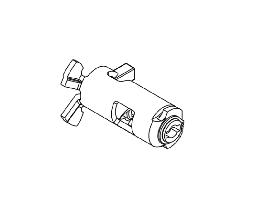
 

Sourcing LCN 8310 Series Parts at Security Parts

Security Parts stocks the full LCN 8310 Series parts catalog, organized by product type. For operator-specific parts by model, browse the operator series pages:

For the complete LCN automatic door operator and parts context, see the door operators parts guide.

Same-day shipping is available on stocked 8310 components. For pre-order compatibility support, wireless upgrade consultation, or package configuration assistance, call 845-935-0301. Pre-order compatibility checks take two minutes and prevent the wrong-configuration return cycle on time-sensitive projects.


About the Author

This guide was written by the Security Parts team, a commercial door hardware specialist serving locksmiths, facilities managers, general contractors, and access control integrators since 2001. Security Parts stocks the full LCN 8310 Series parts catalog including actuators, sensors, switches, relays, wireless kits, and safety packages, with same-day shipping on stocked items and pre-order compatibility support at 845-935-0301.

LCN Senior Swing IQ Parts Guide: 2810IQ, 2850IQ and 2860IQ Replacement Components

Quick Answer

The LCN Senior Swing IQ is the current-generation low-energy electromechanical swing door operator from LCN. It comes in three overhead concealed models and four surface-applied variants. Before ordering any replacement part, three things must be confirmed:

  • Model series: 2810IQ (single door concealed), 2850IQ (simultaneous pair concealed), 2860IQ (independent pair concealed), or 9530IQ/9540IQ/9550IQ/9560IQ (surface-applied).
  • Controller and motor gearbox rule: The IQ controller (3462) and IQ motor gearbox (3454) must always be replaced together. They are not individually backward-compatible with each other or with legacy 9500/2800 hardware.
  • Legacy upgrade: If upgrading from a 9500 or 2800 Senior Swing to the IQ generation, the SSIQUPGRADE kit is the correct order, not individual parts.

Security Parts stocks LCN Senior Swing IQ parts across all models with same-day shipping on stocked components. Call 845-935-0301 for pre-order compatibility support. Browse the complete catalog on the Senior Swing series page.


What the LCN Senior Swing IQ Is and Why the IQ Generation Matters for Parts

The LCN Senior Swing IQ is the current generation of LCN's heavy-duty low-energy electromechanical swing door operator. It is rated for doors up to 600 pounds and carries certifications including Grade 1 ANSI/BHMA A156.19, UL325, UL228, UL10C, ADA compliance, and CSFM listing. It meets the Buy American Act requirement, which is a common specification requirement on government and federally funded projects.

The distinction between the IQ generation and the previous 9500/2800 Senior Swing matters most when ordering parts. The two generations are not parts-compatible at the component level. The IQ controller and motor gearbox use an updated communication architecture called AdaptIQ that the previous controller and gearbox do not support. Parts look similar, but part numbers are different and the assemblies are not interchangeable.

For a full overview of the legacy 9500/2800 Senior Swing and the LCN Benchmark 9130/9140/9150 operators, including their parts and how they differ from the IQ generation, see the LCN Benchmark and Senior Swing automatic door operator parts guide.


What AdaptIQ Technology Does and Why It Matters

AdaptIQ is the self-calibrating control system built into the Senior Swing IQ controller. After installation or after a new controller is fitted, the operator runs a calibration cycle through the LCD menu. During calibration, the door opens slowly to its full open position and then closes. The controller uses this cycle to estimate the door weight, opening resistance, and physical constraints, then sets default operating parameters automatically.

This is why the IQ controller requires no seasonal adjustments for wind, carpet pressure, or HVAC stack pressure. The Smart Power Boost feature within AdaptIQ monitors the closing cycle and adds motor force when environmental resistance increases, keeping the door latching reliably across different seasonal conditions without manual adjustment. Every time a new controller is installed, this calibration must be run before the door will operate on its normal cycle.


Senior Swing IQ Model Families: Concealed vs Surface Applied

The Senior Swing IQ is available in two mounting families:

  • 2800 Series (concealed overhead): 2810IQ for single doors, 2850IQ for simultaneous pairs, 2860IQ for independent pairs. The operator mounts inside a concealed header above the door opening.
  • 9500 Series (surface applied): 9530IQ and 9540IQ for single doors (pull-side and push-side respectively), 9550IQ for simultaneous pairs, 9560IQ for independent pairs. The operator body is visible on the door frame face.

The controller (3462) and motor gearbox (3454) part numbers are the same across concealed and surface-applied models. Headers, arms, and mounting hardware differ between the two families.

For the broader context of how automatic door operators fit into a commercial access control specification, see the access control integration guide and the commercial door operators guide.


LCN Senior Swing IQ Parts: The Two Components That Always Replace Together

The most important ordering rule on the Senior Swing IQ is this: when the controller fails, both the controller and the motor gearbox must be replaced at the same time. When the motor gearbox fails, same rule applies. The two components communicate through a proprietary protocol and are not individually backward-compatible, either with each other or with the previous generation of hardware.


Controller: 2810IQ-3462

LCN 2810IQ-3462 controller replacement part for Senior Swing IQ single door operator

LCN 2810IQ-3462 controller. View product page and order.


The controller is the brain of the Senior Swing IQ system. It houses the LCD display, the 23 programmable settings, the AdaptIQ calibration system, the fire/breakaway relay interface, and the accessory power output for connected sensors and actuators. The controller outputs 48VDC to the motor gearbox and accepts 120VAC or 240VAC building power input.

The controller part number for all 2810IQ, 2850IQ, and 2860IQ overhead concealed models is 2810IQ-3462. The 2850IQ uses the same controller to drive both motor gearboxes in a simultaneous pair through a single control board.

When a controller is replaced, the fire/breakaway jumper (part number 47955791) must remain in the terminal block connector (J18) on the chassis board unless a physical breakaway switch is wired in its place. If the jumper is removed and no switch is wired in, the controller will treat the circuit as an open breakaway condition and will not operate the door.


Motor Gearbox: 2810IQ-3454

LCN 2810IQ-3454 motor gearbox replacement for Senior Swing IQ overhead concealed operator

LCN 2810IQ-3454 motor gearbox. View product page and order.


The motor gearbox drives the spindle that the pivot arm connects to. It physically opens and holds the door. A motor gearbox failure typically presents as the door failing to open, opening only partway, or the controller reporting a motor encoder error on the LCD display.

The motor gearbox part number for 2810IQ, 2850IQ, and 2860IQ installations is 2810IQ-3454. For the 2850IQ simultaneous pair, two motor gearboxes are required: one per door. The companion cable (982) connects the second motor gearbox back to the single controller.

When the motor gearbox is replaced, the arm must be removed and re-installed after the new gearbox is mounted. The arm set screw must be torqued correctly to the spindle, and a full AdaptIQ calibration cycle must be run after re-installation to re-establish correct operating parameters.


LCN Senior Swing IQ Arms: Center Pivot vs Offset/Butt Arm

LCN 2810IQ-3077CP center pivot arm for Senior Swing IQ center-pivoted door installations

LCN 2810IQ-3077CP center pivot arm. View product page and order.


The Senior Swing IQ uses two distinct arm types depending on how the door is hung. Ordering the wrong arm is one of the most common parts return reasons on this product.

  • Center pivot arm (3077CP): Used when the door has a center pivot at the floor and the header. The arm connects directly from the motor gearbox spindle to a slide channel in the door. This is the standard concealed-header arm for center-pivoted commercial entries. Order: 2810IQ-3077CP.
  • Offset/butt arm (3077OP): Used for doors hung on standard butt hinges or offset pivots, where no floor pivot exists. This arm accommodates the geometry of a butt-hung door swinging on its hinge point rather than a center pivot. Order: 2810IQ-3077OP.

To confirm which arm a device uses, look at the bottom of the door at the threshold. A center pivot installation has a visible pivot point at the floor; a butt hinge installation has standard hinges on the door frame edge. Do not attempt to fit a center pivot arm on a butt-hung door. The geometry is incompatible and the arm will not seat correctly on the spindle or door slide.


LCN Senior Swing IQ Stops: Breakaway and Positive

Two types of door stops are available for the Senior Swing IQ. Each serves a different function and applies to different installation configurations.


Breakaway Stop

The breakaway stop is a safety device that allows a center-pivoted inswing door to break outward in an emergency, even when the operator is powered on and holding the door in the closed position. In breakaway mode, the stop releases the pivot mechanism and the door can swing outward freely. The operator is automatically disabled in breakaway mode.

The breakaway stop part number depends on the model:

The breakaway stop applies to center pivot installations only. It is not used on butt hinge or offset pivot installations.


Positive Fixed Stop

The positive fixed stop prevents an outswing door from swinging back inward past the closed position. It is the appropriate stop for outswing door configurations on center pivot installations where inward movement must be blocked. Order: 2810IQ-384F for the 2810IQ, with equivalent variants for the 2850IQ and 2860IQ.


2850IQ and 2860IQ: Double Door Configuration Parts

LCN 2850IQ-3462 controller for simultaneous double door Senior Swing IQ installations

LCN 2850IQ-3462 controller for simultaneous pair installations. View product page and order.


The 2850IQ and 2860IQ handle double door openings, but they operate differently.

  • 2850IQ (simultaneous pair): One controller drives two motor gearboxes. Both doors open and close together in a synchronized cycle. The second motor gearbox connects back to the controller via the companion cable (2850IQ-982). For the 2850IQ, two motor gearboxes plus one controller plus one companion cable is the complete drive assembly.
  • 2860IQ (independent pair): Each door operates on its own cycle. Both doors share a header but can open and close independently. The wiring and control architecture differs from the 2850IQ, even though the component part numbers are identical.

A common ordering mistake on the 2850IQ is ordering only one motor gearbox for a simultaneous pair replacement. Both motor gearboxes must be replaced together, along with the controller, when a drive assembly failure occurs on the 2850IQ. The companion cable should also be inspected and replaced if there is any sign of pinching, damage, or connector wear.


LCN Senior Swing IQ Header and Structural Parts

The header is the concealed channel installed above the door opening that houses the operator components. On the Senior Swing IQ, the header comes in single-door and double-door configurations and in variants with or without the stop preparation cutout.

Key header and structural parts include:

  • Header extrusion (572): The aluminum extrusion only, without end caps or assembly hardware. Ordered when the extrusion is damaged but mounting hardware is intact. Order: 2810IQ-572.
  • Header assembly (3572HL): The complete single-door header assembly including all components. Order: 2810IQ-3572HL.
  • Bottom pivot assembly (3107): The floor-level pivot assembly for center pivot installations. The pivot assembly carries the weight of the door at the threshold and is subject to wear on high-traffic openings. Order: 2810IQ-3107.
  • Cable/parts bag (518): Includes the wiring harnesses, mounting hardware, and installation components supplied with the operator. Available as a replacement when original installation hardware is lost or damaged. Order: 2810IQ-518.


How to Upgrade from Legacy 9500 or 2800 Senior Swing to the IQ Generation

If the existing installation uses the previous-generation 9500 (surface) or 2800 (concealed) Senior Swing, the IQ controller and motor gearbox can be installed in the existing header without replacing the header itself. Both components must be replaced together.

LCN provides the SSIQUPGRADE kit specifically for this upgrade path:

  • SSIQUPGRADE-SD: Upgrade kit for single door installations (2810IQ/9530IQ/9540IQ).
  • SSIQUPGRADE-DD: Upgrade kit for simultaneous pair installations (2850IQ/9550IQ).

The upgrade kit includes the new IQ motor gearbox, the new IQ controller, a plastic filler plate for the control box location, and all required wiring and hardware. Legacy key/rocker switches can be connected using the legacy adapter harness (part number 48179392) included with the upgrade kit. After installation, the AdaptIQ calibration cycle must be run from the controller LCD menu before the door will operate on its standard automatic cycle.

Call 845-935-0301 before placing the upgrade order to confirm the correct kit for the specific installation and to verify header compatibility.


LCN Senior Swing IQ Parts Reference Table

Component2810IQ Part2850IQ Part2860IQ Part
Controller2810IQ-34622850IQ-34622860IQ-3462
Motor Gearbox2810IQ-34542850IQ-34542860IQ-3454
Bottom Pivot Assembly2810IQ-31072850IQ-31072860IQ-3107
Center Pivot Arm2810IQ-3077CP2850IQ-3077CP2860IQ-3077CP
Offset/Butt Arm2810IQ-3077OP2850IQ-3077OP2860IQ-3077OP
Breakaway Stop2810IQ-384B2850IQ-384BK2860IQ-384BK
Positive Fixed Stop2810IQ-384F2850IQ-384F2860IQ-384F
Cable/Parts Bag2810IQ-5182850IQ-5182860IQ-518
Companion CableN/A (single door)2850IQ-9822860IQ-982
Header Assembly2810IQ-3572HL2850IQ header2860IQ header
Header Extrusion2810IQ-5722850IQ-5722860IQ-572


Where LCN Senior Swing IQ Operators Are Specified

The Senior Swing IQ serves any opening on an accessible route where a low-energy automatic operator is required. The most common installation environments include:

  • Healthcare: Patient room corridors, pharmacy entries, and outpatient clinic entrances where ADA force requirements and hands-free passage are mandatory. See the healthcare door hardware guide.
  • Retail storefronts: High-traffic customer entries on aluminum storefront frames where the concealed overhead profile keeps the door entrance uncluttered. See the retail storefront door hardware guide.
  • Universities and colleges: Library entries, administration building corridors, and student union entrances where accessibility is required alongside high pedestrian volume. See the university door hardware guide.
  • Government and institutional buildings: Where the Buy American Act specification is required in addition to ADA compliance.

The ANSI/BHMA A156.19 standard governs the force, cycle, and obstruction reversal requirements for all low-energy operators including the Senior Swing IQ. For a full reference on ANSI/BHMA hardware standards relevant to commercial door specifications, see the ANSI/BHMA door hardware standards guide. For fire door compliance considerations when specifying automatic operators on fire-rated assemblies, see the commercial door fire rating guide.
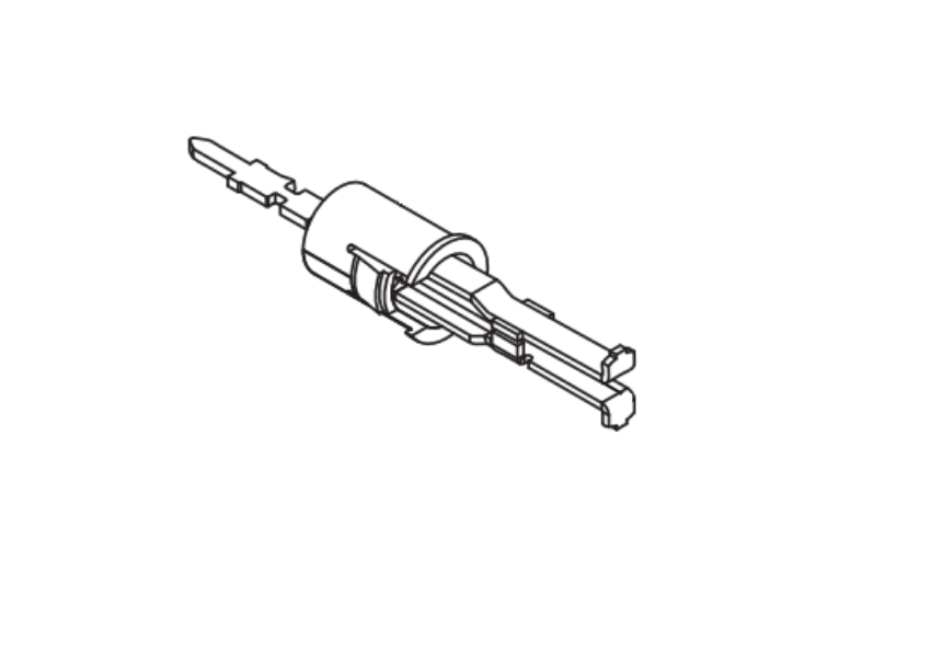
 

Sourcing LCN Senior Swing IQ Parts at Security Parts

Security Parts stocks LCN Senior Swing IQ parts across the full 2810IQ, 2850IQ, and 2860IQ families, organized by model. Browse the complete parts list for each series:

For interactive parts diagrams, use the diagram pages: 2810 diagram 1 and 2850 diagram 1 provide exploded views of the full assembly with component callouts to confirm the failing part before ordering.

Same-day shipping is available on stocked components. Pre-order compatibility support is available at 845-935-0301 before the order is placed. For the full LCN automatic door operator catalog including parts for the Benchmark 9130/9140/9150 and the legacy 9500/2800 Senior Swing, see the door operators parts guide.


About the Author

This guide was written by the Security Parts team, a commercial door hardware specialist serving locksmiths, facilities managers, general contractors, and access control integrators since 2001. Security Parts stocks LCN Senior Swing IQ parts across the full 2810IQ, 2850IQ, and 2860IQ families, with same-day shipping on stocked items and pre-order compatibility support at 845-935-0301.

Von Duprin QEL Conversion Kit: Complete Ordering Guide

Quick Answer

The Von Duprin QEL conversion kit upgrades an existing mechanical or EL-equipped exit device to quiet electric latch retraction. Before you order, you need to answer four questions:

  • Which series is your device? 22 Series uses a completely separate kit family. All other series (33A/35A, 75/78, 94/95, 98/99) share the same modular and baseplate kit catalog.
  • Mechanical or EL upgrade? Mechanical devices use the modular kit. EL solenoid devices require the baseplate kit.
  • Do you need AX, CON, or HD options? AX is for ADA force compliance, CON is the Allegion Connect wiring adapter, and HD adds hex dogging (panic devices only).
  • Is the device fire-rated? If yes, HD-QEL and HD-QELX kits are prohibited. Use standard QEL or QELX only.

Security Parts stocks all Von Duprin QEL conversion kit variants with same-day shipping on stocked components. Call 845-935-0301 before ordering if the application is a 94/95 INPACT Series device. Those require a configured part number.


What the Von Duprin QEL Conversion Kit Does

The QEL (Quiet Electric Latch) is Von Duprin's motor-driven electric latch retraction option for commercial exit devices. When an electric signal is sent from an access control system, keypad, or key switch, the QEL motor retracts the latch bolt, allowing the door to be pulled open from the outside without pressing the push bar.

The word "quiet" distinguishes it from the older EL (Electric Latch) option, which uses a solenoid that produces an audible click during latch retraction. The QEL motor is significantly quieter, making it the preferred specification for hospitals, libraries, museums, theaters, and any environment where operational noise is disruptive.

The conversion kit is the field-installable version. It upgrades an existing mechanical device or replaces a failed QEL motor without requiring a full exit device replacement. Two kit types exist: the modular kit and the baseplate kit. Understanding which one applies to your device is the first and most important step.

For background on how QEL compares to MEL and when to specify each, see the Von Duprin panic bar QEL vs MEL selection guide. For a complete overview of which series use the QEL, see the Von Duprin series guide.


Modular vs Baseplate: Which Von Duprin QEL Conversion Kit Do You Need?

This is the decision most technicians get wrong on the first order. The two kit types are not interchangeable and serve different upgrade scenarios.

Von Duprin 114317 QEL modular conversion kit for mechanical exit device upgrade

Von Duprin 114317 QEL modular conversion kit. View product page and order.


The Modular Kit: For Mechanical Device Upgrades and Motor Replacement

The modular kit is the recommended solution for most applications. It replaces only the motor assembly inside the existing baseplate. The baseplate itself stays on the door. Because the motor assembly fits both 3-foot and 4-foot devices, you do not need to specify device size when ordering. This flexibility is why the modular kit has become the standard upgrade path for mechanical devices.

Use the modular kit when:

  • You are upgrading a mechanical exit device to QEL for the first time
  • You are replacing a failed QEL motor on an existing QEL device
  • The existing device is not an EL solenoid device

The primary modular kit part number for 33A/35A and 98/99 Series devices is 114317. HD-QEL modular (with hex dogging, panic devices only) is 958002.


The Baseplate Kit: For EL Solenoid Device Conversions

Von Duprin 958003 QEL baseplate conversion kit for EL solenoid device upgrade to QEL

Von Duprin 958003 QEL baseplate conversion kit (3-foot). View product page and order.


The baseplate kit replaces the full baseplate assembly, replacing the entire back plate of the exit device, not just the motor. This is required when the existing device uses an EL solenoid, because the solenoid is mounted to the baseplate and cannot simply be removed and replaced with a motor.

Use the baseplate kit when:

  • Your existing device is an EL (Electric Latch) solenoid device
  • You need to convert from solenoid-driven to motor-driven latch retraction

The baseplate kit requires device size specification at order time. The 3-foot kit is 958003 and the 4-foot kit is 040065. Baseplate kits are available for the 33A/35A and 98/99 Series only. They are not available for the 75/78 Series or the 22 Series.


Von Duprin QEL Conversion Kit Ordering Table

Use this table to identify your kit by series, option combination, and device type. All part numbers in the table are verified live on the Security Parts catalog.

SeriesAXCONHDModular KitBaseplate 3ft / 4ft
33A/35A, 98/99NNN114317958003 / 040065
33A/35A, 98/99NNY (panic only)958002958004 / 040067
33A/35A, 98/99NYN040061040063 / 040066
33A/35A, 98/99NYY (panic only)040062040064 / 040068
33A/35A, 98/99YNN041162041166 / 041167
33A/35A, 98/99YNY (panic only)041164041170 / 041171
33A/35A, 98/99YYN041163041168 / 041169
22 SeriesNNN47857518N/A (modular only)
22 SeriesNNY (panic only)47857519N/A (modular only)
22 SeriesYYN47857521N/A (modular only)
75/78 SeriesUse modular kit only. See the 75/78 Series guide.Same as 33A/35A modularN/A (no baseplate kit)
94/95 INPACTConfigured CONVERT.XXXX part number required. Call 845-935-0301.


Understanding the Von Duprin QEL Conversion Kit Options

Every QEL conversion kit is built around a base motor assembly. The three option designations modify that base. Understanding each option is what allows you to select the correct part number from the table above without calling in every time.


AX Option: ADA-Compliant Force Reduction (QELX)

The AX option, designated QELX, meets the 2010 ADA Standards for Accessible Design requirement that operable parts on accessible routes shall not require more than 5 pounds of force to activate. The QELX motor provides reduced activation force to meet this standard.

Specify QELX when the opening is on an accessible route required to comply with ADA force requirements. For a broader discussion of how ANSI/BHMA standards apply to commercial door hardware specification, see the ANSI/BHMA door hardware standards guide.


CON Option: Allegion Connect Wiring Adapter

The CON designation means the kit includes the Allegion Connect adapter harness, which provides a pre-wired connector for quick connection to compatible power sources without field wire termination. If your installation uses a standard PS900 Series power supply with field-terminated wiring, you do not need the CON version.

The CON adapter harness is also available as a standalone part if you need to add the Allegion Connect interface to an existing QEL installation: 106198 QEL CON Adapter Harness. The QEL motor cable for non-CON installations is 114320 QEL Motor Cable, and the combined cable with CON harness is 47269206 QEL/MEL Motor Cable with 6-inch harness.


HD Option: Hex Dogging (Panic Devices Only)

The HD (Hex Dogging) option allows the electric latch retraction device to be manually dogged using a 5/32-inch hex key, holding the latch bolt retracted so the door swings freely during business hours without requiring an electric signal. This is useful in high-traffic commercial applications.

HD-QEL and HD-QELX kits are available for panic exit hardware only. They cannot be used on fire-rated exit hardware. This is a code compliance requirement, not a mechanical limitation. If a fire-rated device requires QEL with an accessible option, order QELX without the HD designation.


22 Series QEL Conversion Kit: What Makes It Different

Von Duprin 47857518 22 Series QEL conversion kit for 22 Series exit device upgrade

Von Duprin 47857518 22 Series QEL conversion kit. View product page and order.

The 22 Series exit device uses a different mechanism case design from the 33A/35A and 98/99 Series, which means it requires its own dedicated QEL kit family. The 33A/35A and 98/99 modular kits will not fit a 22 Series device.

Three important restrictions apply to the 22 Series QEL kits:

  1. Modular kits only. No baseplate conversion kit exists for the 22 Series. If a 22 Series device needs to go from EL to QEL, a full device replacement is required.
  2. Manufacture date matters. 22 Series modular QEL kits are compatible only with devices manufactured after January 1, 2022. Devices with a seam visible on the mechanism case are pre-2022 units and require a full device replacement to achieve QEL capability.
  3. No 3-foot vs 4-foot designation needed. The 22 Series QEL kit is size-universal.

For 22 Series parts and configuration context, see the Von Duprin 22, 33A/35A, and 55 Series exit device parts guide.


QEL-L and QEL-B: Specialty Option Kits

QEL-L: Latch Retraction Only with Active Pushpad

Von Duprin 47897873 QEL-L modular latch retraction with CON adapter for active pushpad installations

Von Duprin 47897873 QEL-L modular latch retraction with CON. View product page and order.

The standard QEL retraction allows the door to be pushed open from the outside without depressing the push bar during an electric signal. The QEL-L changes that behavior: it retracts the latch bolt on signal, but the push bar must still be depressed to open the door.

This is used when the opening requires controlled latch retraction for access control purposes, but the push bar must remain active, for example, in a supervised egress application or a delayed-egress installation where residents must interact with the push bar even when the latch is retracted.

The QEL-L kit includes an RX switch for door status monitoring. Available kits:


QEL-B: Audible Notification Buzzer

Von Duprin 47856044 QEL-B modular buzzer kit for audible latch retraction notification

Von Duprin 47856044 QEL-B modular buzzer kit. View product page and order.


The QEL-B kit adds an audible buzzer that sounds during initial latch bolt retraction. This provides occupants with a clear signal that the door has been released and can be opened. It is specified when silent retraction would cause confusion or when the application requires an audible notification as part of the access protocol.

Part number: 47856044 QEL-B Modular Buzzer Kit.


Fire Door Restriction: The Rule That Cannot Be Overlooked

The single most critical restriction in the Von Duprin QEL conversion kit catalog is the fire door prohibition on HD and HD-X kits. This is not a preference or a recommendation. It is a code requirement.

Fire-rated exit hardware must latch on every closing cycle, without exception, to maintain the fire barrier. Hex dogging holds the latch bolt retracted. These two requirements are incompatible.

On fire-rated exit devices:

  • Order standard QEL or QELX kits only
  • Never order HD-QEL or HD-QELX kits
  • If the device has a fire label, the HD designation voids it
  • The QEL wiring on fire-rated devices must be connected to the fire alarm system so the latch retracts on alarm signal

For a complete reference on fire door hardware requirements and how they affect exit device specification, see the commercial door fire rating guide.
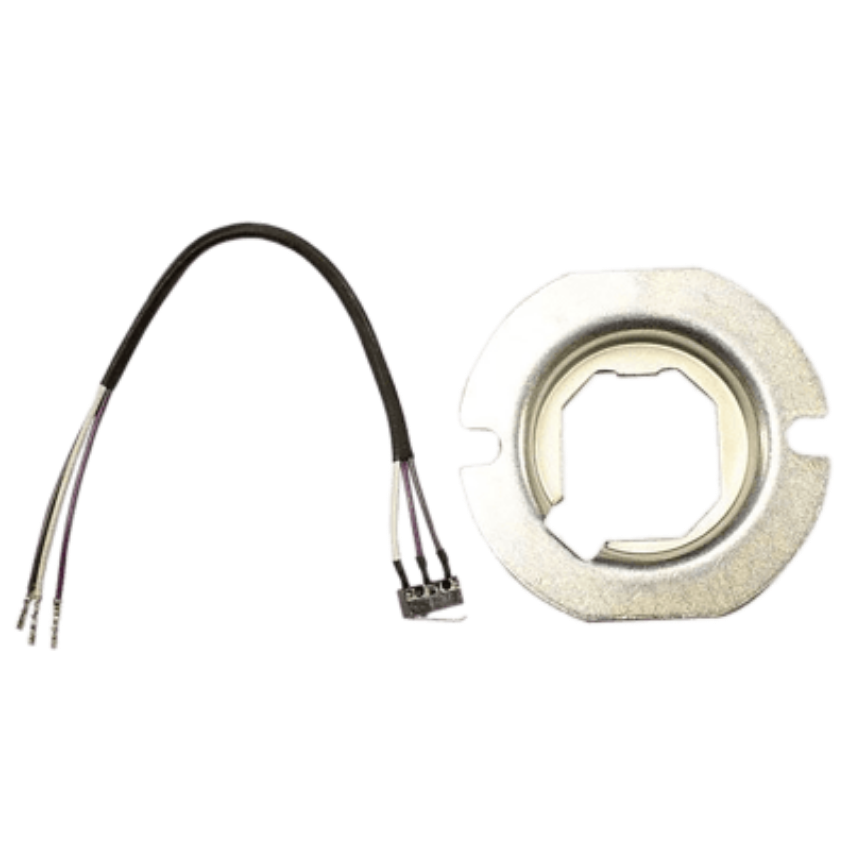
 

Power Supply Requirements for the Von Duprin QEL Conversion Kit

The QEL requires 24VDC from a compatible power supply. Using 12VDC will cause the LED on the QEL board to flash red and the latch bolt will not retract. The following power supplies and option boards are compatible:

Power SupplyRequired Option BoardOutput Setting
PS902, PS904, PS906, PS914900-2RS, 900-4R, or 900-4RL24VDC
PS873871-2, 871-2Q, or 873-4TD/AO24VDC

The QEL is also compatible with an existing 900-2Q option board if one is already installed in the power supply. Up to two sequenced QEL devices can share one 900-2RS board; the latch retraction of two sequenced devices requires more than one second to complete.

For guidance on how the QEL integrates with broader access control system architecture, see the access control integration guide.


How to Select and Order the Right Von Duprin QEL Conversion Kit

Work through these five questions in order. The answers map directly to the ordering table above.

  1. What series is the device? Confirm 22 Series, 33A/35A, 75/78, 94/95 INPACT, or 98/99. The 22 Series uses its own kit family. 94/95 INPACT requires a configured part number from Security Parts. 75/78 Series uses the same modular kits as 33A/35A and 98/99 but has no baseplate option.
  2. Mechanical device or EL solenoid? Mechanical devices use the modular kit. EL solenoid devices require the baseplate kit (33A/35A and 98/99 only).
  3. Device size (if baseplate or QEL-L)? Specify 3-foot (36-inch) or 4-foot (48-inch) for baseplate kits and QEL-L kits. Modular kits for mechanical upgrades are size-universal.
  4. Options needed? Select AX (QELX) for ADA force compliance, CON for Allegion Connect wiring, and HD for hex dogging on panic devices only. These can be combined (example: HD-QELX with CON is 041165).
  5. Fire-rated device? If the device has a fire label, remove HD from the selection immediately and confirm you are ordering a standard QEL or QELX kit.

Security Parts stocks Von Duprin QEL conversion kit variants across all series with same-day shipping on stocked components. Pre-order compatibility support is available at 845-935-0301 before the order is placed. Browse the full exit devices catalog and the Von Duprin parts hub for complete series coverage with model-specific diagrams. For exit device parts guides organized by series, see the Von Duprin parts guide and the Von Duprin exit device series comparison


About the Author

This guide was written by the Security Parts team, a commercial door hardware specialist serving locksmiths, facility managers, general contractors, and access control integrators since 2001. Security Parts stocks Von Duprin QEL conversion kits across all active series and options, with same-day shipping on stocked items and pre-order compatibility support at 845-935-0301.

Schlage NDE Wireless Lock Parts: Complete Replacement Guide

Quick Answer

The Schlage NDE is a Grade 1 wireless cylindrical lock that integrates an RFID/Bluetooth credential reader, motorized latch chassis, door position sensor, and access control interface into a standard cylindrical lock form factor. When servicing one, here are the parts ordered most often:

  • Inside escutcheon assembly with PCBA: 47278749 (the primary NDEB component, also used for NDE80 upgrades)
  • Motorized chassis: N223-007
  • Battery holder kit: N223-044
  • Outside spring cage: N523-218
  • Inside spring cage (post-Feb 2017 devices): N523-221
  • Main wire harness: N223-019
  • Mounting kit: N223-049
  • Battery cover: N623-007


Critical note before ordering: After replacing the inside escutcheon assembly or the motorized chassis on any NDEB device, the lock must be re-commissioned through ENGAGE. Skipping this step produces a lock that will not connect to the access control system. Also confirm whether your device is a pre-February 2017 unit before ordering spring cages, as spring cage part numbers differ by manufacture date.


What the Schlage NDE Wireless Lock Is and Why It Requires Different Parts

The Schlage NDE is not a mechanical lock with an electronic add-on. It is a purpose-built wireless electronic access control device in a cylindrical lock form factor. Identifying this distinction matters because NDE parts are not compatible with the standard Schlage ND Series mechanical cylindrical lock, even though both products mount on the same door preparation and use similar lever hardware.

The NDE combines several systems into a single unit: a Grade 1 cylindrical lock chassis, an RF credential reader, a motorized latch retraction assembly, a door position sensor, a Bluetooth module for ENGAGE communication, and a battery power system. Each of those systems has its own serviceable components. When one fails, you need to identify the right assembly before ordering, because the NDE's internal architecture is substantially different from any mechanical cylindrical lock.

The NDE product line spans three generations. The NDE80 was the original model. It has been discontinued and NDE80-specific parts are no longer available from the manufacturer. The NDEB is the current production standard and is the model you are most likely to encounter on doors installed after 2014. The NDEBSi adds HID secure sector credential compatibility with a visual indicator button. If you have an NDE80 in the field, Security Parts carries the NDEB conversion kit to bring it to current specification.

For context on how the NDE fits into the broader Schlage product lineup and how it differs from the mechanical ND Series, see the Schlage ND Series cylindrical lock parts guide. For a broader look at how wireless locks integrate with commercial door access control systems, see the access control integration guide.


Schlage NDE Wireless Lock Parts: Every Assembly and Component

The NDE parts catalog divides into six functional assemblies. Understanding which assembly you are servicing before ordering prevents wrong-part returns and callback visits. Security Parts stocks NDE components across all six of these categories.


Inside Escutcheon Assembly: The Core Electronic Module

Schlage 47278749 NDEB inside escutcheon assembly with main PCBA for NDE wireless lock replacement

Schlage 47278749 NDEB inside escutcheon assembly with main PCBA. View product page and order.


The 47278749 NDEB inside escutcheon assembly is the single most important component in the NDE parts catalog. It contains the inside escutcheon housing, the RF window, the door position sensor, the main PCB module with Bluetooth radio, and the inside label. When the lock fails to communicate with ENGAGE, fails to read credentials, or produces electrical fault codes, this assembly is the first component to evaluate.

The 47278749 also serves as the NDE80-to-NDEB upgrade kit. If you have an NDE80 in the field, ordering this assembly and following the NDEB retrofit installation instructions brings the unit to the current NDEB specification. After installation, the device must be deleted from ENGAGE, factory default reset, and re-commissioned. This step is required without exception.

The inside escutcheon assembly is also the component that determines whether the lock can support the NDEBSi credential format. If an NDEBSi-capable lock is needed, a new complete lock unit must be ordered. Upgrading an existing NDEB to NDEBSi through parts replacement is not possible.


Motorized Chassis: The Mechanical-Electronic Interface

Schlage NDE N223-007 motorized chassis assembly replacement for wireless cylindrical lock

Schlage NDE N223-007 motorized chassis assembly. View product page and order.


The N223-007 motorized chassis assembly is what translates the electronic credential signal into physical latch retraction. When a valid credential is presented, the motorized chassis retracts the latch bolt. When an invalid credential is presented, or when no signal is received, the chassis holds the latch in the extended position.

The most common symptom of a failing motorized chassis is a latch that retracts slowly or inconsistently, or a device that produces grinding sounds during a valid credential event. Physical impacts and door abuse can damage the chassis alignment. High-cycle environments such as hospital corridors or university residence halls also produce accelerated wear on this component.

Replacing the motorized chassis requires ENGAGE re-commissioning. The replacement chassis does not inherit the previous device's credential programming. Delete the device from ENGAGE, factory reset the chassis, and re-commission before returning the door to service.


Battery System Components

Schlage NDE N223-044 battery holder kit for wireless cylindrical lock replacement

Schlage NDE N223-044 battery holder kit. View product page and order.


The NDE is battery-powered. The battery system involves three serviceable components: the battery holder kit, the battery cover, and the inside baseplate that anchors both.

  • N223-044 Battery Holder Kit: The primary battery housing assembly. Replaced during routine maintenance cycles when battery contacts corrode or when the physical holder cracks from door cycling stress. The kit contains the holder and retaining hardware.
  • N623-007 Inside Battery Cover: The cover plate that protects the battery compartment. Replaced when damaged from repeated access or when the battery cover screw strips. Order the battery cover screw separately using the N223-049 mounting kit.
  • N623-000 Inside Baseplate: The mounting plate behind the inside escutcheon that anchors the battery and spring cage components to the door. Replaced when the baseplate warps from door stress or when mounting threads strip.


Spring Cages: Confirm Manufacture Date Before Ordering

Schlage NDE N523-218 outside spring cage and lever catch assembly replacement

Schlage NDE N523-218 outside spring cage and lever catch assembly. View product page and order.


Spring cage ordering on the NDE requires one piece of information before you place the order: the manufacture date of the device. Devices manufactured after February 1, 2017 use a different inside spring cage than those manufactured before that date. Using the wrong spring cage produces a lever that will not seat correctly or will not hold under use.

  • N523-218 Outside Spring Cage and Lever Catch Assembly: Applies to all NDE devices regardless of manufacture date. The outside spring cage is universal. Replace when the outside lever droops, fails to return to position after each use, or when the catch mechanism no longer holds the lever in place.
  • N523-221 Inside Spring Cage and Lever Catch Assembly: Applies to devices manufactured after February 1, 2017. Confirm the manufacture date on the label inside the device before ordering. If your device was manufactured before that date, contact Security Parts at 845-935-0301 to confirm the correct alternative spring cage for your specific unit.

For full-size interchangeable core configurations that use specific non-Schlage IC cores, the outside spring cage changes to N523-224. Confirm with the NDE service manual whether N523-224 applies to your core specification. All other cylinder configurations use N523-218 for the outside position.


Wire Harness, Reader PCBA, and Electronic Accessories

The electronic components between the credential reader and the chassis are the second most common source of NDE service calls after the inside escutcheon assembly. These include:

  • N223-019 Main Wire Harness: Connects the inside escutcheon PCBA to the motorized chassis. When physical or environmental damage breaks a wire, credential reads produce no mechanical response. Inspect the harness routing before replacing the escutcheon or chassis, since a harness fault can mimic either failure.
  • N223-046 Reader PCBA: The credential reading board inside the outside escutcheon. Replaced when the lock stops reading credentials altogether but the ENGAGE connection remains active and the motor still functions on a manual test.
  • N223-045 Outside Escutcheon Subassembly: The complete outside housing assembly without the reader PCBA. The escutcheon without reader is specified for installations where the credential reader is not required but the physical outside trim must be replaced. Specify finish when ordering.
  • N623-030 Motor Assembly: The motor sub-assembly within the motorized chassis. In some service scenarios the motor itself fails while the chassis body remains intact. Confirm with the manufacturer service manual whether your specific failure mode calls for the motor assembly alone or the full motorized chassis N223-007.


Mounting Hardware and Installation Tools

Schlage 40-286 Universal Clamp for NDE NDEB door preparation template installation

Schlage 40-286 Universal Clamp for NDE/NDEB door preparation template. View product page and order.


Any installation that involves the full inside escutcheon replacement or an NDE80 upgrade requires the correct installation tools. These are not optional:

  • 40-286 Universal Clamp: Required for use with the NDEB door preparation template. The template cannot be used accurately without the clamp. Works across the NDE, LE, AD, and CO Series installation templates.
  • 47286225 NDEB Door Preparation Template: Required for new door prep and for NDE80-to-NDEB upgrades, which require additional door position sensor holes that the original NDE80 installation did not create. Must be used with the 40-286 clamp.
  • 40-292 Door Position Sensor Fixture and Mounting Hardware: Required for accurate door position sensor (DPS) hole placement. The 47286225 template is required to use the 40-292 fixture.
  • N223-049 Mounting Kit Screw: The standard mounting hardware kit for NDE installations. Contains combination screws, mounting screws, machine screws, battery cover screws, pan head screws, and a pin wrench.


Cylinder and Tailpiece Options for the Schlage NDE

The NDE supports three cylinder configurations. Each uses a different tailpiece. When ordering levers that include a cylinder, you must specify which core configuration is required, because each lever comes factory-configured for a specific cylinder type.

Cylinder TypeTailpiece Part NumberNotes
Schlage KIL (key-in-lever)N523-022High security Schlage proprietary core
Full-size IC (FSIC)N523-127Schlage FSIC core driver
Small format IC (SFIC)N523-091Schlage SFIC core driver

If you are uncertain which cylinder type is installed in your specific NDE device, the core type is identified on the label inside the battery compartment. For guidance on how master key systems and interchangeable core cylinder programs integrate with commercial door hardware at the facility level, see the master key system design guide and the Schlage key systems guide.


NDE Wireless Lock Parts Quick Reference Table

Part NumberDescriptionNotes
47278749NDEB Inside Escutcheon Assembly with PCBANDE80-to-NDEB upgrade; ENGAGE re-commission required
N223-007Motorized Chassis AssemblyENGAGE re-commission required after replacement
N223-044Battery Holder KitContains holder and retaining hardware
N223-019Main Wire HarnessInspect before replacing escutcheon or chassis
N223-045Outside Escutcheon SubassemblyWithout reader PCBA; specify finish
N223-046Reader PCBAReplace when credentials stop reading but motor still functions
N523-218Outside Spring Cage and Lever Catch AssemblyUniversal; all NDE manufacture dates
N523-221Inside Spring Cage and Lever Catch AssemblyDevices manufactured after February 1, 2017 only
N223-049Mounting KitContains all screws plus pin wrench
N623-000Inside BaseplateAnchors spring cage and battery components
N623-007Inside Battery CoverOrder N223-049 for replacement cover screw
N623-030Motor AssemblySub-assembly within N223-007 chassis
47286225NDEB Door Preparation TemplateRequired with 40-286 universal clamp
40-286Universal ClampRequired for use with door prep template
40-292Door Position Sensor FixtureRequired with 47286225 template
47269850TKE TransponderWireless gateway transponder for ENGAGE network


Ordering Schlage NDE Wireless Lock Parts: What to Confirm Before You Call

NDE parts ordering has more variables than mechanical lock parts because the electronic configuration affects which components are compatible. Confirm these five items before placing any order:

  1. NDE80 or NDEB? Look for a label inside the battery compartment. The model designation tells you which inside escutcheon assembly applies and whether an upgrade kit is needed.
  2. Manufacture date. The date is stamped on the label inside the battery compartment. This determines which inside spring cage applies. Pre- and post-February 2017 devices use different spring cage part numbers.
  3. Cylinder type. KIL, FSIC, or SFIC. This determines which tailpiece applies and which lever part numbers are valid for your configuration.
  4. Finish. Specify finish for levers, escutcheons, strikes, and latches. Not specifying finish results in a shipment in the manufacturer's default finish, which may not match the door hardware.
  5. ENGAGE version. Before replacing the inside escutcheon or motorized chassis, confirm you have access to the current ENGAGE app for re-commissioning. Part replacement without re-commissioning produces a non-functional installation.

Security Parts stocks Schlage NDE wireless lock parts with same-day shipping on available components. Pre-order compatibility support is available at 845-935-0301. For OEM versus aftermarket part considerations on electronic access control hardware, see the OEM vs aftermarket commercial door hardware guide.


Schlage NDE in Context: How It Differs from Other Schlage Cylindrical Locks

The NDE shares its door preparation (the 61 Series prep with minor modifications) and lever form factor with the mechanical ND Series and the ALX Series. This means it can be installed on the same door as a mechanical lock replacement with minimal door modification. However, the internal components are completely different and do not cross between the product lines.

The mechanical Schlage ND Series cylindrical lock parts guide covers the ND, NDT, and NDB mechanical cylindrical line. If you are servicing a cylindrical lock that does not have a Bluetooth indicator or battery compartment on the inside trim, you have a mechanical ND Series device, not an NDE. The Schlage ALX Series guide covers the ALX10 through ALX80 mechanical cylindrical line, which uses similar lever hardware but entirely different internal mechanisms.

For facilities managing a mix of NDE wireless locks and other access control hardware, the access control integration guide covers how ENGAGE-platform devices communicate with third-party access control systems, credential formats, and door position sensor wiring. Understanding the integration architecture before servicing an NDE device prevents credential programming loss and unnecessary service calls.

The NDE is commonly specified in the same facilities as electric strikes and electrified mortise locks. For electric strike parts, see the electric strike parts guide. For function code selection guidance that applies across all commercial cylindrical lock types, see the commercial lock function codes guide.

The NDE is particularly common in healthcare and government facilities. For door hardware specification requirements in those environments, see the healthcare door hardware guide and the government buildings door hardware guide. For a complete picture of ANSI/BHMA Grade 1 certification requirements that the NDE meets, see the ANSI/BHMA door hardware standards guide.


About the Author

This guide was written by the Security Parts team, a commercial door hardware specialist serving locksmiths, facility managers, general contractors, and access control integrators since 2001. Security Parts stocks OEM and aftermarket replacement components for Schlage and other leading commercial hardware manufacturers, with same-day shipping on stocked items and pre-order parts identification support at 845-935-0301.

Von Duprin 9927 Surface Vertical Rod Parts: Complete Ordering Guide


Von Duprin 98/9927 surface vertical rod exit device for double door openings

Von Duprin 98/9927 surface vertical rod exit device. Browse all 9927 SVR parts.


Quick Answer

The Von Duprin 9927 is the grooved-case surface vertical rod (SVR) configuration of the 99 Series exit device. It uses exposed top and bottom rods to provide three-point locking on double doors without a center post. The key parts you will order most often are:

  • Top rod kit: 050512 (for standard doors up to 7'1")
  • Bottom rod kit: 050514
  • Top latch kit: 050400 (post-October 1998 devices) or 050091 (pre-1998 retrofit)
  • Bottom latch kit: 050401 (post-October 1998) or 050090 (pre-1998 retrofit)
  • Center case: 109358 (SVR configuration, both panic and fire)
  • Rod guide package: 112063

The 9927 uses a grooved case. The 9827 has a smooth case. They are not interchangeable. Always verify your model number before ordering any part.


What the Von Duprin 9927 SVR Actually Does

The 9927 is the surface vertical rod configuration of the Von Duprin 99 Series, one of the most widely installed institutional exit device families in North America. It is designed for double door openings where there is no center mullion or fixed door post to mount a strike.

When someone presses the push bar, the center case mechanism simultaneously retracts a top latch bolt into a strike at the door head and a bottom latch bolt into a floor or threshold strike. This three-point engagement is what gives the SVR device its holding strength and is why it is specified on high-traffic egress doors in schools, healthcare facilities, government buildings, and commercial properties.

The rods run on the surface of the door face, which is what distinguishes the SVR from the concealed vertical rod (CVR) device. If you are working on a device where the rods are hidden inside the door stile, you have a CVR, not an SVR. See the Von Duprin 9947 CVR exit device parts guide for that configuration.

For a complete overview of how the 9927 fits within the broader Von Duprin product family, see the Von Duprin series guide.


9927 vs 9827: How to Tell Them Apart Before You Order

This is the most common ordering mistake on the 98/99 Series SVR device. The 9827 and 9927 look nearly identical in the field, but their rod kits and some center case components are not interchangeable.

Feature9827 (98 Series)9927 (99 Series)
Mechanism caseSmoothGrooved
Top rod kit050513050512
Bottom rod kit050515050514
Center case (SVR)109358109358
Latch kits (post-1998)050400 / 050401050400 / 050401
Rod kits interchangeable?NoNo

The model number is stamped on the mechanism case, which sits in the center of the push bar channel. On the 9927, the grooved finish on the case surface is visible under good lighting even with the cover in place. If you are still unsure which device you have, call Security Parts at 845-935-0301 before ordering.


Von Duprin 9927 Surface Vertical Rod Parts: Every Category Explained

The parts catalog for the 9927 SVR divides into eight functional categories. Each one covers a specific area of the device and requires careful attention to configuration before ordering. Browse the full Von Duprin 98/9927 SVR parts catalog for the complete part listing with diagrams.


Vertical Rod Kits and Extension Rods

Von Duprin 98/9927 vertical rods and latches parts diagram showing top and bottom rod assemblies

Von Duprin 98/9927 vertical rods and latches diagram. View all rod and latch parts.


The vertical rods are the most frequently replaced components on an SVR device. They wear at the latch engagement points and bend from impacts by carts, gurneys, and high-traffic door cycling.

  • 050512 Top Rod Kit: Standard top rod for the 9927, handles doors up to 7 feet 1 inch. The rod is 34 and 15/16 inches long. Field adjustable for doors shorter than the standard height.
  • 050513 Top Rod Kit: This is the 9827 top rod. Not for the 9927.
  • 050514 Bottom Rod Kit: Standard bottom rod for the 9927. Rod length is 31 and a half inches, standardized by building code requirements that set the device centerline height at 39 and 5/8 inches from the finished floor.
  • 050515 Bottom Rod Kit: This is the 9827 bottom rod. Not for the 9927.
  • ER-60 Extension Rod (60"): Required when the door height exceeds 7 feet 1 inch. Available in 12-inch and 36-inch extension lengths. Extension rod kits include the rod and the rod-to-rod connector hardware.

When replacing rods, also check the rod roll pins (090054), rod connectors (090067 for latch side, 090068 for center case side), and the rod extension connector package (090075). These small components wear alongside the rods and are cheap insurance against a callback.


Latch Kits: Confirm Your Manufacture Date First

Von Duprin changed the latch design in October 1998. The pre-1998 latches are not compatible with the post-1998 kits. Using the wrong latch kit is one of the most common service errors on older 9927 devices.


For devices manufactured after October 1998:

  • 050400: Top latch kit, less cover. Used on the 2227, 3327A, and 9927 SVR devices shipped after October 1998. Includes the top latch assembly and mounting screws.
  • 050401: Bottom latch kit, less cover. Same post-1998 application. The bottom latch on the 9927 interfaces with the floor or threshold strike.
  • 050546: Latch mounting bracket kit. Used with 050400 and 050401 on post-1998 devices.
  • 050566: Latch case cover kit for the 98/9927 and 9927-F. Covers both top and bottom latch cases.


For devices manufactured before October 1998:

  • 050091: Top latch retrofit kit. Replaces and updates the pre-1998 top latch to the current design. If the bottom rod is dragging on the floor on an older device, a worn or failed latch is almost always the cause.
  • 050090: Bottom latch retrofit kit. Same pre-1998 retrofit application.

Supporting latch hardware that wears alongside the latch assemblies includes the latch mounting package (900589), latch case cover screws (900850 in packs of two), and the rod guide mounting package (900919).


Rod Guide Package

The rod guide keeps the surface rods from bowing, deflecting, or bending under lateral impact from carts and equipment that pass through high-traffic doorways. On an SVR device, the rod guides are one of the first components to show wear.

  • 112063: Rod guide package for the 98/9927. Sold in pairs. The current version of this guide includes a metal strap and a nylon bushing that the rod slides through, which is a significant improvement over the original spring-and-cover design.
  • 900919: Rod guide mounting package. Includes the mounting hardware for the 112063 guides.

Check the rod guides whenever you are replacing rods. A bent rod on a properly maintained device usually means the guides have failed first.


Baseplate Assembly

Von Duprin 98/9927 and 9927-F baseplate assembly parts diagram

Von Duprin 98/9927 baseplate assembly. View baseplate parts.


The baseplate is the mounting plate that secures the device to the door face. Baseplate hardware includes the sex bolt package (034902, pack of two), the mounting screw packages, and the baseplate itself. The sex bolt package uses the 325 hex head bolts and is required at both the top and bottom latch positions.

The baseplate assembly applies to both the panic 9927 and the fire-rated 9927-F. Confirm door thickness before ordering mounting hardware, as screw lengths differ between 1-3/4 inch and 2-1/4 inch door applications.


Center Case Assembly

Von Duprin 98/9927 center case assembly and 9927-F LBR fire latch kit parts diagram

Von Duprin 98/9927 center case assembly and LBR fire latch kit. View center case parts.


The center case is the heart of the SVR device. It houses the push bar mechanism, the dogging assembly, and the control link that operates both the top and bottom rods simultaneously.

The 9927 SVR uses center case 109358. This is a critical distinction: the rim device (98/99) uses center case 109012, and these two are completely different. Ordering the rim center case for an SVR device will result in a non-functional installation.

The center case for the double door configuration uses part number 109358 for both the panic and fire versions. If you have a double cylinder device (model 9927-2), you will also need the CC-CVR-2-98/9927 center case cover kit.

Internal center case components that can be serviced separately include:

  • 090056: Top latch compression spring (pack of 10)
  • 090057: Pullman latch spring (pack of 10), used when the device is equipped with a Pullman latch option
  • 090058: Bottom latch case spring (pack of 10)
  • 090065: Bolt return spring (pack of 10)
  • 090076: Auxiliary bolt spring (pack of 10)


Dogging Assembly: Panic vs Fire Configuration

Von Duprin 98/9927 dogging diagrams for hex dogging and cylinder dogging configurations

Von Duprin 98/9927 dogging configuration diagrams. View dogging diagrams.

Dogging allows the push bar to be held in the depressed position, effectively converting the exit device into a free-swinging door. This is used in high-traffic situations during business hours. The 9927 supports two types of dogging:

Hex dogging (HD) is the standard option. It uses a 5/32-inch hex key inserted into a socket on the cover plate to dog the push bar in the depressed position. The hex dogging shaft (090040) is the most commonly replaced dogging component. It strips when a misaligned hex key is forced into the socket or when the socket wears from repeated use.

Cylinder dogging (CD) replaces the hex key with a key cylinder. The technician turns the key to dog and undog the device. Cylinder dogging is used in applications where key control over the dogged state is needed. The CD option requires the specific cylinder dogging housing and actuator components found in the CD center case assembly.

The fire-rated 9927-F does not support dogging of any kind. A fire exit hardware device must latch every time the door closes, without exception. If you have a -F suffix on your model number, do not attempt to add dogging hardware.

For devices shipped before August 1997, old-style dogging parts apply. The old-style hex dogging replacement kit is 050153. See the service replacement items section in the 98/99 Series parts manual for the complete old-style parts list.


Fire Exit Hardware: The 9927-F and LBR Configuration

The 9927-F is the fire exit hardware version of the 9927 SVR. It carries UL listing for fire exit hardware and is certified to ANSI/BHMA A156.3 Grade 1. Understanding the differences between the panic and fire versions prevents ordering errors that result in non-compliant installations.

Feature9927 (Panic)9927-F (Fire)
Dogging permittedYes (HD and CD)No
LBR (Less Bottom Rod) availableNoYes
UL fire exit listingNoYes
Center case109358109358
Top strike299299F
Bottom strike (standard)304L304L
Bottom strike (panic-rated)248L-4248L-4

The LBR (Less Bottom Rod) configuration on the 9927-F removes the bottom vertical rod and substitutes a spring-loaded bottom latch. This is used in applications where a threshold or floor obstruction prevents a standard bottom rod and strike installation, or where ADA-compliant accessible thresholds are required. The LBR requires its own fire latch kit: 050171.

For a complete explanation of fire rating categories and what they mean for exit device selection, see the commercial door fire rating guide.
 

Strikes: Matching the Right Strike to Your Configuration

The 9927 SVR uses separate top and bottom strikes. Strike selection depends on whether you have a panic or fire device and whether you need a panic-rated bottom strike for high-security applications.

  • 299: Standard top strike for the 9927 panic device. Mounts at the door header.
  • 299F: Fire-rated top strike for the 9927-F.
  • 304L: Standard vertical rod bottom strike. Used at the floor or threshold for both the panic 9927 and the fire 9927-F in most installations.
  • 248L-4: Panic-rated vertical rod bottom strike for high-security applications. Provides additional holding strength compared to the standard 304L.

On wood doors, a wood door screw pack (964291) is required for the strikes. For doors where the strike cannot be recessed, an optional surface strike is available.


Electrified Options: EL, QEL, ALK, and RX

The 9927 panic device supports several electrified and monitoring upgrade options. These are specified when the opening requires access control integration, alarm monitoring, or electric latch retraction. None of these options are available on the fire-rated 9927-F.


Electric Latch Retraction (EL)

The EL option adds a solenoid to the push bar mechanism that retracts the latch bolt on an electric signal, allowing the door to be opened from the outside without pressing the push bar. The EL solenoid replacement kit is available for devices that have an existing EL installation. For devices shipped before January 1987, the old-style EL solenoid parts apply (050218 replacement kit).

The HD-EL combination option (hex dogging with electric latch retraction) is also available as a factory-installed configuration on the panic device.


ALK Exit Alarm Kit

The ALK kit adds a battery-powered local alarm to the 9927 push bar. When the push bar is depressed without authorization, the alarm sounds. The ALK is used in applications that require door monitoring without a full access control system. The ALK kit diagram and part numbers are available in the 9927 SVR parts catalog.


RX and LX Monitoring Options

The RX (Request to Exit) option adds a switch to the push bar that signals an access control system when the bar is pressed. The LX option (Latch Bolt Monitor) adds a switch that monitors the position of the latch bolt. Both provide real-time door status signals for building security systems. The RX and LX options apply to the panic device only.

For guidance on how these electrified options integrate with commercial door access control systems, see the exit devices parts guide.


Double Cylinder Configuration: The 9927-2 and 9927-2SI

Von Duprin 98/9927-2 double cylinder surface vertical rod exit device model diagram

Von Duprin 98/9927-2 double cylinder model. View double cylinder parts.


The double cylinder option (designated with the -2 suffix) adds a key cylinder to the outside of the device. This allows the latch bolt to be operated from the outside by key, in addition to the standard push bar operation from the inside.

The -2SI variant (Security Indicator) adds a visual flag that shows whether the device is in a secured or unsecured state. This is used in applications where supervisory verification of the lock status is needed.

Conversion kits are available for upgrading an existing 9927 to the double cylinder or security indicator configuration:

  • 2SIKIT-2-98/9927: Double cylinder conversion kit for the 9927 series.
  • 2SIKIT-2SI-98/9927: Security indicator conversion kit for the 9927 series.
  • CC-CVR-2-98/9927: Center case cover kit for the double cylinder configuration.


9927 SVR Parts Quick Reference by Part Number

Part NumberDescriptionNotes
0505129927 Top Rod KitDoors up to 7'1"
0505149927 Bottom Rod KitStandard length, 31.5 inches
050400Top Latch Kit (post-Oct 1998)Also fits 2227, 3327A
050401Bottom Latch Kit (post-Oct 1998)Also fits 2227, 3327A
050091Top Latch Retrofit Kit (pre-Oct 1998)Updates old-style latch
050090Bottom Latch Retrofit Kit (pre-Oct 1998)Updates old-style latch
112063Rod Guide PackageSold in pairs
109358Center Case (SVR, panic and fire)Not interchangeable with 109012 (rim)
034902325 Sex Bolt Package (Pkg of 2)Top and bottom latch mounting
050566Latch Case Cover KitCovers top and bottom latch cases
050171LBR Fire Latch Kit9927-F only, Less Bottom Rod config
ER-6060" Extension Rod KitDoors above 7'1"
299 / 299FTop Strike (panic / fire)Mounts at door header
304LStandard Vertical Rod Bottom StrikeMounts at floor or threshold
248L-4Panic-Rated Vertical Rod Bottom StrikeHigher security applications


How the 9927 SVR Fits in the 98/99 Series Family

The 98/99 Series spans three primary physical configurations that cover different door types and architectural requirements. Understanding where the 9927 sits helps you navigate the catalog correctly when you are managing a facility with mixed device types.

  • Rim device (98/99): Single-point latch at the frame strike. Used on single doors. Center case 109012.
  • Surface vertical rod (9827/9927): Three-point locking on double doors without a center post. Rods visible on door surface. Center case 109358. That is what this guide covers.
  • Concealed vertical rod (9847/9947): Three-point locking on double doors where concealed hardware is required. Rods run inside the door stile. See the Von Duprin 9947 CVR exit device parts guide for that configuration.

For a complete side-by-side breakdown of all 98/99 Series configurations, see the Von Duprin 98/99 Series exit device parts guide. For configuration selection guidance across the entire Von Duprin product line, see the Von Duprin exit device series comparison.


Ordering the Right 9927 SVR Parts: What to Confirm Before You Place the Order

Getting the right parts the first time on a 9927 SVR comes down to five questions. Have the answers ready before you call or click.


  1. Is the mechanism case smooth or grooved? Smooth is the 9827. Grooved is the 9927. This determines your rod kit part numbers.
  2. Is there an -F suffix on the model number? If yes, you have fire exit hardware. Dogging parts do not apply. LBR may apply.
  3. When was the device manufactured? Pre-October 1998 devices need retrofit latch kits (050090/050091). Post-October 1998 devices use the standard kits (050400/050401).
  4. What is the door height? Standard rods handle up to 7 feet 1 inch. Taller doors need an extension rod kit.
  5. Does the device have any options? Double cylinder (-2), security indicator (-2SI), electric latch retraction (EL or QEL), cylinder dogging (CD), and ALK alarm all require specific additional components.


Security Parts stocks OEM and aftermarket replacement components for the full Von Duprin 98/9927 SVR catalog. Same-day shipping on stocked components from US warehouses. Free shipping on orders over $450. If you need help confirming the right part for your specific device, call 845-935-0301 before the order goes through. Browse the complete Von Duprin 98/9927 SVR parts catalog or the Von Duprin parts hub for every other active series.

For context on the broader 98/99 Series service history and the part number changes that affect older devices, see the Von Duprin 98/99 Series parts manual. For guidance on selecting the right exit device configuration for a new or replacement installation, see the Von Duprin panic bar selection guide.


About the Author

This guide was written by the Security Parts team, a commercial door hardware specialist serving locksmiths, facility managers, general contractors, and service technicians since 2001. Security Parts stocks OEM and aftermarket replacement components for Von Duprin and other leading commercial door hardware manufacturers, with same-day shipping on stocked items and pre-order parts identification support at 845-935-0301.

Von Duprin 9927 Surface Vertical Rod Parts: Complete Ordering Guide


Von Duprin 98/9927 surface vertical rod exit device for double door openings

Von Duprin 98/9927 surface vertical rod exit device. Browse all 9927 SVR parts.


Quick Answer

The Von Duprin 9927 is the grooved-case surface vertical rod (SVR) configuration of the 99 Series exit device. It uses exposed top and bottom rods to provide three-point locking on double doors without a center post. The key parts you will order most often are:

  • Top rod kit: 050512 (for standard doors up to 7'1")
  • Bottom rod kit: 050514
  • Top latch kit: 050400 (post-October 1998 devices) or 050091 (pre-1998 retrofit)
  • Bottom latch kit: 050401 (post-October 1998) or 050090 (pre-1998 retrofit)
  • Center case: 109358 (SVR configuration, both panic and fire)
  • Rod guide package: 112063

The 9927 uses a grooved case. The 9827 has a smooth case. They are not interchangeable. Always verify your model number before ordering any part.


What the Von Duprin 9927 SVR Actually Does

The 9927 is the surface vertical rod configuration of the Von Duprin 99 Series, one of the most widely installed institutional exit device families in North America. It is designed for double door openings where there is no center mullion or fixed door post to mount a strike.

When someone presses the push bar, the center case mechanism simultaneously retracts a top latch bolt into a strike at the door head and a bottom latch bolt into a floor or threshold strike. This three-point engagement is what gives the SVR device its holding strength and is why it is specified on high-traffic egress doors in schools, healthcare facilities, government buildings, and commercial properties.

The rods run on the surface of the door face, which is what distinguishes the SVR from the concealed vertical rod (CVR) device. If you are working on a device where the rods are hidden inside the door stile, you have a CVR, not an SVR. See the Von Duprin 9947 CVR exit device parts guide for that configuration.

For a complete overview of how the 9927 fits within the broader Von Duprin product family, see the Von Duprin series guide.


9927 vs 9827: How to Tell Them Apart Before You Order

This is the most common ordering mistake on the 98/99 Series SVR device. The 9827 and 9927 look nearly identical in the field, but their rod kits and some center case components are not interchangeable.

Feature9827 (98 Series)9927 (99 Series)
Mechanism caseSmoothGrooved
Top rod kit050513050512
Bottom rod kit050515050514
Center case (SVR)109358109358
Latch kits (post-1998)050400 / 050401050400 / 050401
Rod kits interchangeable?NoNo

The model number is stamped on the mechanism case, which sits in the center of the push bar channel. On the 9927, the grooved finish on the case surface is visible under good lighting even with the cover in place. If you are still unsure which device you have, call Security Parts at 845-935-0301 before ordering.


Von Duprin 9927 Surface Vertical Rod Parts: Every Category Explained

The parts catalog for the 9927 SVR divides into eight functional categories. Each one covers a specific area of the device and requires careful attention to configuration before ordering. Browse the full Von Duprin 98/9927 SVR parts catalog for the complete part listing with diagrams.


Vertical Rod Kits and Extension Rods

Von Duprin 98/9927 vertical rods and latches parts diagram showing top and bottom rod assemblies

Von Duprin 98/9927 vertical rods and latches diagram. View all rod and latch parts.


The vertical rods are the most frequently replaced components on an SVR device. They wear at the latch engagement points and bend from impacts by carts, gurneys, and high-traffic door cycling.

  • 050512 Top Rod Kit: Standard top rod for the 9927, handles doors up to 7 feet 1 inch. The rod is 34 and 15/16 inches long. Field adjustable for doors shorter than the standard height.
  • 050513 Top Rod Kit: This is the 9827 top rod. Not for the 9927.
  • 050514 Bottom Rod Kit: Standard bottom rod for the 9927. Rod length is 31 and a half inches, standardized by building code requirements that set the device centerline height at 39 and 5/8 inches from the finished floor.
  • 050515 Bottom Rod Kit: This is the 9827 bottom rod. Not for the 9927.
  • ER-60 Extension Rod (60"): Required when the door height exceeds 7 feet 1 inch. Available in 12-inch and 36-inch extension lengths. Extension rod kits include the rod and the rod-to-rod connector hardware.

When replacing rods, also check the rod roll pins (090054), rod connectors (090067 for latch side, 090068 for center case side), and the rod extension connector package (090075). These small components wear alongside the rods and are cheap insurance against a callback.


Latch Kits: Confirm Your Manufacture Date First

Von Duprin changed the latch design in October 1998. The pre-1998 latches are not compatible with the post-1998 kits. Using the wrong latch kit is one of the most common service errors on older 9927 devices.


For devices manufactured after October 1998:

  • 050400: Top latch kit, less cover. Used on the 2227, 3327A, and 9927 SVR devices shipped after October 1998. Includes the top latch assembly and mounting screws.
  • 050401: Bottom latch kit, less cover. Same post-1998 application. The bottom latch on the 9927 interfaces with the floor or threshold strike.
  • 050546: Latch mounting bracket kit. Used with 050400 and 050401 on post-1998 devices.
  • 050566: Latch case cover kit for the 98/9927 and 9927-F. Covers both top and bottom latch cases.


For devices manufactured before October 1998:

  • 050091: Top latch retrofit kit. Replaces and updates the pre-1998 top latch to the current design. If the bottom rod is dragging on the floor on an older device, a worn or failed latch is almost always the cause.
  • 050090: Bottom latch retrofit kit. Same pre-1998 retrofit application.

Supporting latch hardware that wears alongside the latch assemblies includes the latch mounting package (900589), latch case cover screws (900850 in packs of two), and the rod guide mounting package (900919).


Rod Guide Package

The rod guide keeps the surface rods from bowing, deflecting, or bending under lateral impact from carts and equipment that pass through high-traffic doorways. On an SVR device, the rod guides are one of the first components to show wear.

  • 112063: Rod guide package for the 98/9927. Sold in pairs. The current version of this guide includes a metal strap and a nylon bushing that the rod slides through, which is a significant improvement over the original spring-and-cover design.
  • 900919: Rod guide mounting package. Includes the mounting hardware for the 112063 guides.

Check the rod guides whenever you are replacing rods. A bent rod on a properly maintained device usually means the guides have failed first.


Baseplate Assembly

Von Duprin 98/9927 and 9927-F baseplate assembly parts diagram

Von Duprin 98/9927 baseplate assembly. View baseplate parts.


The baseplate is the mounting plate that secures the device to the door face. Baseplate hardware includes the sex bolt package (034902, pack of two), the mounting screw packages, and the baseplate itself. The sex bolt package uses the 325 hex head bolts and is required at both the top and bottom latch positions.

The baseplate assembly applies to both the panic 9927 and the fire-rated 9927-F. Confirm door thickness before ordering mounting hardware, as screw lengths differ between 1-3/4 inch and 2-1/4 inch door applications.


Center Case Assembly

Von Duprin 98/9927 center case assembly and 9927-F LBR fire latch kit parts diagram

Von Duprin 98/9927 center case assembly and LBR fire latch kit. View center case parts.


The center case is the heart of the SVR device. It houses the push bar mechanism, the dogging assembly, and the control link that operates both the top and bottom rods simultaneously.

The 9927 SVR uses center case 109358. This is a critical distinction: the rim device (98/99) uses center case 109012, and these two are completely different. Ordering the rim center case for an SVR device will result in a non-functional installation.

The center case for the double door configuration uses part number 109358 for both the panic and fire versions. If you have a double cylinder device (model 9927-2), you will also need the CC-CVR-2-98/9927 center case cover kit.

Internal center case components that can be serviced separately include:

  • 090056: Top latch compression spring (pack of 10)
  • 090057: Pullman latch spring (pack of 10), used when the device is equipped with a Pullman latch option
  • 090058: Bottom latch case spring (pack of 10)
  • 090065: Bolt return spring (pack of 10)
  • 090076: Auxiliary bolt spring (pack of 10)


Dogging Assembly: Panic vs Fire Configuration

Von Duprin 98/9927 dogging diagrams for hex dogging and cylinder dogging configurations

Von Duprin 98/9927 dogging configuration diagrams. View dogging diagrams.

Dogging allows the push bar to be held in the depressed position, effectively converting the exit device into a free-swinging door. This is used in high-traffic situations during business hours. The 9927 supports two types of dogging:

Hex dogging (HD) is the standard option. It uses a 5/32-inch hex key inserted into a socket on the cover plate to dog the push bar in the depressed position. The hex dogging shaft (090040) is the most commonly replaced dogging component. It strips when a misaligned hex key is forced into the socket or when the socket wears from repeated use.

Cylinder dogging (CD) replaces the hex key with a key cylinder. The technician turns the key to dog and undog the device. Cylinder dogging is used in applications where key control over the dogged state is needed. The CD option requires the specific cylinder dogging housing and actuator components found in the CD center case assembly.

The fire-rated 9927-F does not support dogging of any kind. A fire exit hardware device must latch every time the door closes, without exception. If you have a -F suffix on your model number, do not attempt to add dogging hardware.

For devices shipped before August 1997, old-style dogging parts apply. The old-style hex dogging replacement kit is 050153. See the service replacement items section in the 98/99 Series parts manual for the complete old-style parts list.


Fire Exit Hardware: The 9927-F and LBR Configuration

The 9927-F is the fire exit hardware version of the 9927 SVR. It carries UL listing for fire exit hardware and is certified to ANSI/BHMA A156.3 Grade 1. Understanding the differences between the panic and fire versions prevents ordering errors that result in non-compliant installations.

Feature9927 (Panic)9927-F (Fire)
Dogging permittedYes (HD and CD)No
LBR (Less Bottom Rod) availableNoYes
UL fire exit listingNoYes
Center case109358109358
Top strike299299F
Bottom strike (standard)304L304L
Bottom strike (panic-rated)248L-4248L-4

The LBR (Less Bottom Rod) configuration on the 9927-F removes the bottom vertical rod and substitutes a spring-loaded bottom latch. This is used in applications where a threshold or floor obstruction prevents a standard bottom rod and strike installation, or where ADA-compliant accessible thresholds are required. The LBR requires its own fire latch kit: 050171.

For a complete explanation of fire rating categories and what they mean for exit device selection, see the commercial door fire rating guide.
 

Strikes: Matching the Right Strike to Your Configuration

The 9927 SVR uses separate top and bottom strikes. Strike selection depends on whether you have a panic or fire device and whether you need a panic-rated bottom strike for high-security applications.

  • 299: Standard top strike for the 9927 panic device. Mounts at the door header.
  • 299F: Fire-rated top strike for the 9927-F.
  • 304L: Standard vertical rod bottom strike. Used at the floor or threshold for both the panic 9927 and the fire 9927-F in most installations.
  • 248L-4: Panic-rated vertical rod bottom strike for high-security applications. Provides additional holding strength compared to the standard 304L.

On wood doors, a wood door screw pack (964291) is required for the strikes. For doors where the strike cannot be recessed, an optional surface strike is available.


Electrified Options: EL, QEL, ALK, and RX

The 9927 panic device supports several electrified and monitoring upgrade options. These are specified when the opening requires access control integration, alarm monitoring, or electric latch retraction. None of these options are available on the fire-rated 9927-F.


Electric Latch Retraction (EL)

The EL option adds a solenoid to the push bar mechanism that retracts the latch bolt on an electric signal, allowing the door to be opened from the outside without pressing the push bar. The EL solenoid replacement kit is available for devices that have an existing EL installation. For devices shipped before January 1987, the old-style EL solenoid parts apply (050218 replacement kit).

The HD-EL combination option (hex dogging with electric latch retraction) is also available as a factory-installed configuration on the panic device.


ALK Exit Alarm Kit

The ALK kit adds a battery-powered local alarm to the 9927 push bar. When the push bar is depressed without authorization, the alarm sounds. The ALK is used in applications that require door monitoring without a full access control system. The ALK kit diagram and part numbers are available in the 9927 SVR parts catalog.


RX and LX Monitoring Options

The RX (Request to Exit) option adds a switch to the push bar that signals an access control system when the bar is pressed. The LX option (Latch Bolt Monitor) adds a switch that monitors the position of the latch bolt. Both provide real-time door status signals for building security systems. The RX and LX options apply to the panic device only.

For guidance on how these electrified options integrate with commercial door access control systems, see the exit devices parts guide.


Double Cylinder Configuration: The 9927-2 and 9927-2SI

Von Duprin 98/9927-2 double cylinder surface vertical rod exit device model diagram

Von Duprin 98/9927-2 double cylinder model. View double cylinder parts.


The double cylinder option (designated with the -2 suffix) adds a key cylinder to the outside of the device. This allows the latch bolt to be operated from the outside by key, in addition to the standard push bar operation from the inside.

The -2SI variant (Security Indicator) adds a visual flag that shows whether the device is in a secured or unsecured state. This is used in applications where supervisory verification of the lock status is needed.

Conversion kits are available for upgrading an existing 9927 to the double cylinder or security indicator configuration:

  • 2SIKIT-2-98/9927: Double cylinder conversion kit for the 9927 series.
  • 2SIKIT-2SI-98/9927: Security indicator conversion kit for the 9927 series.
  • CC-CVR-2-98/9927: Center case cover kit for the double cylinder configuration.


9927 SVR Parts Quick Reference by Part Number

Part NumberDescriptionNotes
0505129927 Top Rod KitDoors up to 7'1"
0505149927 Bottom Rod KitStandard length, 31.5 inches
050400Top Latch Kit (post-Oct 1998)Also fits 2227, 3327A
050401Bottom Latch Kit (post-Oct 1998)Also fits 2227, 3327A
050091Top Latch Retrofit Kit (pre-Oct 1998)Updates old-style latch
050090Bottom Latch Retrofit Kit (pre-Oct 1998)Updates old-style latch
112063Rod Guide PackageSold in pairs
109358Center Case (SVR, panic and fire)Not interchangeable with 109012 (rim)
034902325 Sex Bolt Package (Pkg of 2)Top and bottom latch mounting
050566Latch Case Cover KitCovers top and bottom latch cases
050171LBR Fire Latch Kit9927-F only, Less Bottom Rod config
ER-6060" Extension Rod KitDoors above 7'1"
299 / 299FTop Strike (panic / fire)Mounts at door header
304LStandard Vertical Rod Bottom StrikeMounts at floor or threshold
248L-4Panic-Rated Vertical Rod Bottom StrikeHigher security applications


How the 9927 SVR Fits in the 98/99 Series Family

The 98/99 Series spans three primary physical configurations that cover different door types and architectural requirements. Understanding where the 9927 sits helps you navigate the catalog correctly when you are managing a facility with mixed device types.

  • Rim device (98/99): Single-point latch at the frame strike. Used on single doors. Center case 109012.
  • Surface vertical rod (9827/9927): Three-point locking on double doors without a center post. Rods visible on door surface. Center case 109358. That is what this guide covers.
  • Concealed vertical rod (9847/9947): Three-point locking on double doors where concealed hardware is required. Rods run inside the door stile. See the Von Duprin 9947 CVR exit device parts guide for that configuration.

For a complete side-by-side breakdown of all 98/99 Series configurations, see the Von Duprin 98/99 Series exit device parts guide. For configuration selection guidance across the entire Von Duprin product line, see the Von Duprin exit device series comparison.


Ordering the Right 9927 SVR Parts: What to Confirm Before You Place the Order

Getting the right parts the first time on a 9927 SVR comes down to five questions. Have the answers ready before you call or click.


  1. Is the mechanism case smooth or grooved? Smooth is the 9827. Grooved is the 9927. This determines your rod kit part numbers.
  2. Is there an -F suffix on the model number? If yes, you have fire exit hardware. Dogging parts do not apply. LBR may apply.
  3. When was the device manufactured? Pre-October 1998 devices need retrofit latch kits (050090/050091). Post-October 1998 devices use the standard kits (050400/050401).
  4. What is the door height? Standard rods handle up to 7 feet 1 inch. Taller doors need an extension rod kit.
  5. Does the device have any options? Double cylinder (-2), security indicator (-2SI), electric latch retraction (EL or QEL), cylinder dogging (CD), and ALK alarm all require specific additional components.


Security Parts stocks OEM and aftermarket replacement components for the full Von Duprin 98/9927 SVR catalog. Same-day shipping on stocked components from US warehouses. Free shipping on orders over $450. If you need help confirming the right part for your specific device, call 845-935-0301 before the order goes through. Browse the complete Von Duprin 98/9927 SVR parts catalog or the Von Duprin parts hub for every other active series.

For context on the broader 98/99 Series service history and the part number changes that affect older devices, see the Von Duprin 98/99 Series parts manual. For guidance on selecting the right exit device configuration for a new or replacement installation, see the Von Duprin panic bar selection guide.


About the Author

This guide was written by the Security Parts team, a commercial door hardware specialist serving locksmiths, facility managers, general contractors, and service technicians since 2001. Security Parts stocks OEM and aftermarket replacement components for Von Duprin and other leading commercial door hardware manufacturers, with same-day shipping on stocked items and pre-order parts identification support at 845-935-0301.

Electric Strikes Complete Guide: Fail-Safe vs Fail-Secure, Fire Doors, Lock Types and Troubleshooting

An electric strike replaces the fixed strike plate in a door frame with a motorized keeper that releases remotely on a credential signal. The lock on the door stays mechanical: the inside lever or push bar always provides free egress. The electric strike only controls entry from the outside. Getting the fail mode right (fail-safe vs fail-secure) and the lock type right (cylindrical vs mortise vs rim) is the entire specification decision. Everything else is installation detail.

Electric strikes are the access control component most often specified incorrectly on commercial door hardware projects. The mistakes fall into two categories: the wrong fail mode for the door's life safety function, and the wrong strike type for the lock installed on the door. Both errors are easily avoided with a clear understanding of how each selection is determined. This guide covers both.

Browse electric strike parts at SecurityParts.com: Von Duprin electric strike parts for commercial access control applications, Von Duprin exit device parts for rim electric strike applications, Schlage L Series mortise lock parts for mortise electric strike pairings, and the complete Allegion access control hardware catalog.

How an Electric Strike Works

A standard fixed strike plate is a passive piece of hardware bolted to the door frame. The latchbolt from the lock extends into the strike pocket and the door stays closed until someone operates the lever from inside or uses a key from outside. An electric strike replaces this fixed plate with an electromechanical device where the keeper (the curved piece that holds the latchbolt) is connected to a solenoid. When the solenoid is activated, the keeper pivots or retracts out of the way, allowing the latchbolt to pass through without being retracted mechanically. The door opens by being pulled or pushed, with the latch still extended, because the keeper is not blocking it.

When the door closes again, the latchbolt re-engages the keeper and the door is latched without any electrical input. The solenoid only needs to activate long enough for the door to be opened: a brief pulse (typically 1 to 5 seconds) is sufficient. This is why electric strikes are energy-efficient in fail-secure mode: they only draw power during the unlock event, not continuously.

The trigger for the solenoid comes from the access control system: a card reader credential event, a keypad code entry, a push-button release, a motion sensor, or a remote switch all send a signal to the access control panel which then applies or removes power from the strike.

Fail-Safe vs Fail-Secure: How Each Works and When Each Is Required

The fail mode is the single most important specification decision for any electric strike. It is determined entirely by the door's role in the building's life safety plan, not by preference, security level, or budget.

Fail-Secure (Fail-Locked)

In fail-secure mode, the strike remains locked when power is lost. Power must be applied to the solenoid to unlock the keeper. When power is removed (either as the normal locked state or during a power failure), a spring extends the keeper and the latchbolt is held positively in the strike. The door cannot be opened from outside without a credential or mechanical key. Free egress from inside is always available through the mechanical lever or push bar, which retracts the latchbolt directly regardless of the strike's electrical state.

Fail-secure is the correct specification for perimeter security doors, storeroom doors, server room doors, restricted area doors, and any door where unauthorized entry during a power failure would be a security breach. It is also the correct specification for fire-rated doors, for reasons explained below.

Fail-Safe (Fail-Open)

In fail-safe mode, the strike unlocks when power is lost. Power must be continuously applied to the solenoid to hold the keeper in the locked position. When power is removed, the keeper releases and the door can be pushed or pulled open without any credential or key. Fail-safe is required on doors that are on a required means of egress and where the door does not have a mechanical means of free egress from inside when the lock is energized.

The life safety code basis for fail-safe is clear: IBC and NFPA 101 require that all egress doors be operable without a key, tool, or special knowledge during emergency evacuation. A fail-secure lock on a required egress door that loses power during a fire leaves occupants unable to exit through that door. Fail-safe eliminates this risk by ensuring the door always unlocks on power loss.

The single question that determines the fail mode: Is this door on the building's required means of egress, AND does it lack a mechanical means of free egress from inside when energized? If yes to both: fail-safe. If no to either (the door is not on required egress, OR the inside lever/push bar always provides mechanical free egress regardless of the electrical state): fail-secure is acceptable. Most commercial electric strike applications pair a fail-secure strike with a mechanical lock that always allows free egress from inside, satisfying the life safety requirement while maintaining outside security on power loss.

Why Fire-Rated Doors Require Fail-Secure Electric Strikes

This is the most commonly misspecified aspect of electric strikes, and the one with the most significant life safety consequence. The misspecification goes in the direction you might not expect: people install fail-safe strikes on fire-rated doors thinking "fail-safe is safer," and they are wrong about fire doors specifically.

NFPA 80 requires that fire door assemblies be positively latching at all times when closed. The latchbolt must engage the strike and hold the door in the closed position. A fire on one side of a door creates pressure that can force the door open if the latch is not positively engaged. If a fail-safe electric strike is installed on a fire-rated door, the keeper retracts when power is lost. With the keeper retracted, only the spring-loaded latch is making contact with an open pocket in the strike. Under fire pressure, the latch can be pushed right through the open pocket, the door opens, and the fire separation is compromised.

A fail-secure strike keeps the keeper extended when power is lost, maintaining positive latching. The latchbolt is held in the keeper as firmly as it would be in a standard fixed strike plate. The fire door performs as designed. This is why NFPA 80 effectively requires fail-secure on fire-rated doors, and why Von Duprin fail-secure strikes carry UL listings for both fire and burglary, while fail-safe strikes carry UL listings for burglary only. The listing label difference is the physical documentation of this code requirement.

The 2003 Cook County Administration Building fire and the stairwell reentry requirement it created: On October 17, 2003, a fire started on the 12th floor of a 35-story building in Chicago's Loop. People evacuating were directed into a stairwell, encountered thick smoke, were told to go back up, and could not reenter floors as they climbed because the stairwell doors locked against reentry. Six people did not survive. Others were hospitalized. This event is the historical origin of the IBC stairwell reentry requirement: stairwell doors must allow reentry from the stair side on every floor in buildings over four stories. This requirement is documented in NFPA 101 and cited in IBC commentary. Electric strikes cannot satisfy both the fire door positive latching requirement (needs fail-secure) and the stairwell reentry requirement (needs fail-safe) on the same door. They simply cannot do both simultaneously. The correct hardware is fail-safe electrified trim on a fire exit hardware device.

Browse Von Duprin fail-secure electric strike parts for fire-rated door applications at SecurityParts.com.

Lock Type Compatibility: Cylindrical, Mortise, and Rim Exit Device

Electric strikes are not interchangeable between lock types. Each lock type presents a different latchbolt geometry, projection length, and mounting position that requires a specifically designed strike keeper. Installing the wrong strike type produces a latch that either cannot engage the keeper, binds against the frame, or provides insufficient security engagement.

Cylindrical Lock Electric Strikes

Cylindrical locks (Schlage ND Series, AL Series) use a spring-loaded latchbolt with a 1/2-inch to 5/8-inch throw. Standard ANSI electric strikes are designed for this geometry and are the most common commercial electric strike type. The ANSI prep in hollow metal frames (the standard cutout for the fixed strike plate) accommodates most ANSI electric strikes with minimal additional frame preparation. One critical installation detail: the deadlatch auxiliary plunger on a cylindrical lock must not contact the electric strike keeper edge. If the plunger falls behind the keeper when the door is closing, it can bind the strike and prevent the keeper from resetting after the door closes. Verify clearance between the deadlatch plunger and the strike keeper edge during installation.

Mortise Lock Electric Strikes

Mortise locks (Schlage L Series) have a latchbolt throw of up to 3/4 inches, which requires a deeper keeper pocket than a cylindrical strike provides. Mortise electric strikes have this deeper keeper pocket. An important limitation: mortise electric strikes only release the latchbolt. The separate deadbolt on a mortise lock is a true deadbolt with no spring return. The electric strike cannot capture and hold a deadbolt: if the deadbolt is extended when the door is opened, the deadbolt projects out and the door closes with the deadbolt extended into empty space. The deadbolt must be retracted before entry through a mortise electric strike, either by keying the deadbolt or with electrified mortise trim that controls the deadbolt electrically.

Rim Exit Device Electric Strikes

Rim exit devices use a Pullman-type latchbolt that is geometrically different from a cylindrical or mortise latch. Rim electric strikes are specifically designed for this geometry and are significantly larger and heavier-duty than cylindrical strikes. They semi-surface mount rather than recess fully into the frame. For double doors with surface vertical rod (SVR) exit devices, the bottom rod is typically deactivated and locking occurs only at the top of the door with a single rim electric strike. The top rod latch type (Pullman, carriage, pin) must be confirmed before selecting the keeper style in the rim electric strike.

Browse Von Duprin electric strike parts for cylindrical, mortise, and rim applications at SecurityParts.com.

Power: 12V vs 24V DC, AC Buzzing, and Wire Run Sizing

DC vs AC: Why Buzzing Happens and How to Fix It

AC-powered electric strikes buzz. The solenoid vibrates at the frequency of the alternating current (60 Hz), producing the characteristic noise. DC-powered strikes operate quietly: the solenoid activates with a soft click and holds silently. For any commercial installation where the electric strike is in a lobby, office entry, or anywhere occupants can hear it, DC power is the correct specification. AC is acceptable only in industrial or mechanical areas where ambient noise masks the buzzing.

If an existing installation is buzzing, add a rectifier between the transformer and the strike to convert AC to DC without replacing the power supply. A rectifier converts the AC waveform to pulsing DC, which significantly reduces solenoid vibration. For the quietest operation on a retrofit, replace the AC supply with a dedicated DC power supply.

12V vs 24V: Voltage Drop on Long Wire Runs

Both 12VDC and 24VDC are standard for electric strikes. For new installations, 24VDC is the better specification: at equal current draw, 24V delivers twice the power, and voltage drop over long wire runs is half as significant as at 12V. For wire runs over 200 feet, a 12V system may not deliver sufficient voltage at the strike to reliably actuate the solenoid. Check the manufacturer's voltage drop tables before finalizing wire gauge and run length. If an existing 12V installation shows intermittent strike release (works sometimes but not others), check the voltage at the strike terminals under load (when the access control panel triggers the release). If the voltage has dropped below the strike's minimum operating voltage, increase the wire gauge or switch to 24V.

Power Supply Sizing: Inrush Current, Not Holding Current

Sizing the power supply to the steady-state holding current is the most common power supply error in electric strike installations. Electric strikes have a momentary inrush current when the solenoid first activates that is significantly higher than the holding current. Size the power supply at 150 percent of the peak inrush current of all strikes that could activate simultaneously. A power supply sized only to holding current may actuate one strike reliably but fail to actuate multiple strikes when they trigger at the same time.

Common Electric Strike Troubleshooting

Strike Not Releasing When Triggered

Check voltage at the strike terminals under load (while the access control panel is sending the unlock signal). Use a multimeter. If voltage is present but the strike does not release, the solenoid may be failed and the strike needs replacement. If voltage is low or absent, check the power supply output, wire connections at the panel, and wire continuity. Voltage drop over long runs is the most common field failure cause.

Strike Releases But Door Does Not Open

The keeper has released but the latch is still engaged in the keeper pocket under door preload pressure. Door preload occurs when the door is pressing against the frame (from air pressure, tight weather stripping, or a slight warp). The latch presses against the keeper even when it retracts. The fix: check door gap at the strike side, adjust the door stop if it is pulling the door too tightly against the frame, and verify that the strike lip is aligned correctly. Some strikes have adjustable lip length to accommodate door gap variation.

Deadlatch Plunger Binding the Keeper

On cylindrical lock installations, the auxiliary deadlatch plunger sits beside the main latchbolt. If the strike keeper geometry allows the plunger to fall behind the keeper edge rather than riding over it, the plunger binds the keeper in the retracted position and the keeper cannot reset after the door closes. This prevents the door from latching on the next closure. The fix: verify that the strike is the correct model for the lock, check the plunger clearance in the strike pocket, and if necessary use a strike with a guard plate or plunger deflector.

Strike Buzzing on DC Power

If a strike that should be DC-powered is buzzing, check whether the power supply output is truly DC or actually AC using a multimeter on the AC voltage setting. Some inexpensive power supplies labeled as DC output deliver unfiltered rectified AC that still contains significant AC ripple. Replace with a filtered, regulated DC power supply.

For electric strike troubleshooting support and OEM replacement parts, contact SecurityParts.com at 845-935-0301 or the SecurityParts.com contact page.

Why Choose SecurityParts.com for Electric Strike Parts

We document the specific NFPA 80 reason fail-safe electric strikes cannot be used on fire-rated doors: keeper retraction on power loss removes positive latching, allowing fire pressure to push the door open. We document the Cook County Administration Building fire as the origin of IBC stairwell reentry requirements and the specific reason electric strikes cannot solve both fire door latching and stairwell reentry simultaneously. We document the deadlatch plunger binding failure mode that is the most common field installation problem on cylindrical lock electric strike applications. We document the 150 percent inrush current rule for power supply sizing and the 200-foot wire run threshold for 12V vs 24V selection.

Browse Von Duprin electric strike replacement parts, Von Duprin exit device parts for rim electric strike pairings, and Schlage L Series mortise lock parts for mortise electric strike applications. Free shipping on orders over $450. Same-day shipping from US warehouses. 30-plus years of commercial door hardware experience.

Frequently Asked Questions 

What is the difference between fail-safe and fail-secure electric strikes?

Fail-secure stays locked when power is lost: power is applied to unlock, spring holds keeper locked without power. Required where security must be maintained during power failure. Fail-safe unlocks when power is lost: power is applied to lock, keeper releases without power. Required on required egress paths where doors must always allow exit during emergencies. The correct fail mode is determined by the door's life safety role, not by security preference.

Why must electric strikes on fire-rated doors be fail-secure, not fail-safe?

NFPA 80 requires fire doors to be positively latching at all times when closed. A fail-safe electric strike retracts its keeper on power loss, leaving only a spring latch in an open pocket. Fire pressure can push the latch through and open the door, compromising the fire separation. A fail-secure strike keeps the keeper extended on power loss, maintaining positive latching. UL listings confirm this: Von Duprin fail-secure strikes carry UL fire and burglary listings; fail-safe strikes carry only a burglary listing.

Can electric strikes be used on stairwell doors that require reentry?

No. A fire-rated stairwell door needs fail-secure for positive latching (NFPA 80) and fail-safe for stairwell reentry (IBC over 4 stories). No single electric strike can satisfy both simultaneously. The correct hardware is fail-safe electrified trim on a fire exit hardware device: the trim unlocks the stair-side lever for reentry while the fire exit hardware maintains latch engagement for fire door compliance. The origin of the reentry requirement is the October 17, 2003 Cook County Administration Building fire in Chicago, where six people died after being unable to reenter floors from a smoke-filled stairwell.

What are the different electric strike types for cylindrical, mortise, and rim exit device locks?

Cylindrical: standard ANSI strikes for 1/2- to 5/8-inch latchbolt. Most common. Check deadlatch plunger clearance at keeper edge. Mortise: deeper keeper pocket for up to 3/4-inch latchbolt. Only releases latchbolt, not deadbolt. Rim exit device: Pullman-type geometry, larger and heavier-duty, semi-surface mounted. Not interchangeable with cylindrical or mortise strikes. Always verify compatibility with the specific lock model, not just the lock type.

Why does an electric strike buzz, and how do I fix it?

AC-powered strikes buzz because the solenoid vibrates at 60 Hz. Fix by adding a rectifier to convert AC to DC, or replacing the power supply with a filtered DC supply. If a DC strike is buzzing, the power supply may be unfiltered rectified AC with significant ripple. Test with a multimeter on AC voltage setting at the strike terminals: true DC should show near-zero on AC setting. Replace with a regulated DC supply.

What is the correct power supply voltage for electric strikes and how do I size the power supply?

Prefer 24VDC for new installations: half the current draw of 12V at equal power, better performance on long wire runs. For wire runs over 200 feet, 12V may not deliver sufficient voltage reliably. Size the power supply at 150 percent of the peak inrush current of all strikes that could activate simultaneously, not to the steady-state holding current. An undersized supply fails to actuate multiple strikes simultaneously even if it handles a single strike reliably.

Commercial Door Hardware for Parking Garages: Exit Devices, Stairwell Locks and Corrosion-Resistant Hardware Guide

Parking garages are one of the harshest environments for commercial door hardware. Road salt, moisture, vehicle exhaust, and extreme temperature swings destroy standard commercial hardware in a few years. Stairwell doors in structures over 4 stories have specific reentry requirements under the IBC. Exit devices on pedestrian doors need to be Grade 1 and, on exposed or semi-exposed openings, should carry the Von Duprin OUT outdoor-rated designation. This guide covers what you need, why the environment matters, and how to order the right parts.

A parking garage looks simple on paper: concrete, cars, and a handful of pedestrian doors. In practice, it is one of the most demanding hardware environments in commercial construction. The combination of road salt chlorides, condensation from temperature swings, vehicle exhaust, andonstant mechanical use from people who are often carrying items or moving quickly creates failure rates that surprise property managers who spec standard commercial hardware and expect the same service life they get from interior office building doors.

Browse parking garage hardware parts at SecurityParts.com: Von Duprin OUT outdoor-rated exit device parts for parking garage stairwell doors, LCN 4040XP EDA door closer parts for parking garage pedestrian entries, Schlage ND Series cylindrical lock parts for stairwell interior doors, and the complete Allegion hardware catalog.

Why Standard Door Hardware Fails in Parking Garages

The failure mechanism is not complicated: chloride ions from road salt eat through steel-based hardware finishes and reach the base metal. Once the base metal is exposed, corrosion accelerates. Standard commercial finishes like satin chrome over zinc die-cast or painted steel over carbon steel are not designed to resist the chloride concentration you get in a parking structure that serves a northern climate market for six months of the year.

There are four specific conditions that together create this environment. First, direct moisture from rain, snow, and wash-off from vehicles entering the structure. Open-sided garages have no wall protection from weather. Even enclosed garages see condensation on hardware surfaces from the temperature differential between outside air and interior air. Second, road salt tracked in on tires. Every vehicle that enters in winter months brings chloride-laden slush into the structure. It evaporates. The chloride stays. Third, vehicle exhaust. Combustion byproducts create slightly acidic condensation on surfaces, which accelerates the corrosion process on both finishes and lubricants inside hardware mechanisms. Fourth, temperature swings. A northern garage might see ambient temperatures ranging from negative ten degrees to positive ninety degrees Fahrenheit across a year. Hydraulic closer fluid viscosity changes with temperature, and hardware finish adhesion is stressed by this repeated thermal cycling.

The practical consequence: a standard commercial exit device or cylindrical lock installed in a parking garage stairwell that sees high salt exposure will typically show visible corrosion within two years and functional failure within three to five years. Hardware specified for the environment lasts a decade or more.

The corrosion that happens inside the mechanism, not just on the surface: Property managers who specify outdoor-rated finishes but standard internal mechanisms are partially solving the problem. The visible surface corrosion is arrested. But standard internal springs, cams, and latch components made from carbon steel still corrode when chloride-laden moisture enters the mechanism case through gaps in the housing. Von Duprin's OUT designation modifies both the external finish and the internal components and adds weep holes to drain water that enters the case. Hardware specified for outdoor exposure should carry the OUT designation throughout, not just a corrosion-resistant finish on standard internal parts.

Von Duprin OUT Option: Outdoor-Rated Exit Devices for Parking Structures

Von Duprin's OUT option is available on the 98/99 Series exit devices and designates a configuration specifically engineered for moisture, temperature variation, and corrosion resistance in exterior and semi-exposed applications. Von Duprin describes OUT as designed for courtyards, perimeter security, rooftops, and patios: the same environmental conditions present in open parking garage stairwells and pedestrian exit doors.

The OUT designation includes corrosion-resistant coatings on internal mechanism components, hardware selected for outdoor exposure throughout the device, and weep holes in the mechanism case that allow water to drain rather than pool and corrode internal parts. For parking garage stairwell exit doors that are open to exterior air and moisture, the OUT option is the correct specification for the 98/99 Series exit device.

The Von Duprin 22 Series is also worth considering for parking garage stairwell applications. Von Duprin specifically identifies the 22 Series as ideal for back-door employee entrances and parking garage stairwells. The 22 Series is a medium-duty touch bar device (not push pad) designed for medium to low traffic openings where aesthetics and cost are considerations. For low-traffic stairwell doors in smaller parking structures, the 22 Series provides a simpler, more economical alternative to the full 98/99 Series. Browse Von Duprin exit device parts for parking garage applications at SecurityParts.com.

Stairwell Requirements in Parking Garages Over 4 Stories

The IBC requires stairwell reentry on buildings and structures over four stories above grade. NFPA 101 includes similar provisions. The intent is to prevent occupants from being trapped in a stairwell during an emergency: if every stairwell door allows reentry from the stair side on every floor, a person who enters the stairwell can exit at any level if the stairwell becomes unusable and find an alternative means of egress.

In a parking garage context, this means that in a structure with more than four levels above grade, every stairwell door must be equipped with hardware that allows reentry from the stair side without a key. The stairwell doors are still self-closing and positively latching (fire exit hardware on fire-rated enclosures), and they can be secured against entry from the parking floors during after-hours periods using electrified access control. But the stair side must always allow exit.

Fail-Safe Electrified Trim for Stairwell Reentry

The most common hardware for parking garage stairwell reentry doors is fail-safe electrified trim on a Von Duprin exit device. The exit device provides the push-bar egress from the parking floor side and the fire exit hardware listing for the fire-rated stairwell enclosure. The electrified trim on the stair side is fail-safe: it unlocks automatically on power loss, ensuring that anyone in the stairwell can reenter a floor even during a power failure. During business hours, the trim is typically unlocked for free access. During after-hours periods, the access control system can require a credential on the parking floor side while maintaining free reentry from the stair side.

Browse Von Duprin exit device parts with fail-safe electrified trim for stairwell reentry at SecurityParts.com.

Door Closers for Parking Garage Pedestrian Entry Doors

Parking garage pedestrian entry doors see high cycle counts from commuters, shoppers, and building tenants moving quickly, often with hands full. The LCN 4040XP with Extra Duty Arm (EDA) is the correct specification for these openings. The EDA adds a forged steel main arm and forearm to the standard 4040XP aluminum arm, preventing the arm-bending deformation that eventually stops a lighter arm from fully closing a door under repeated high-force operation.

For exterior pedestrian entry doors exposed to wind, the 4040XP's backcheck valve should be set to limit the door travel and prevent the arm from being damaged if the door is caught by a gust. The hold-open position on these doors is typically not desired for security reasons: a pedestrian entry door held open allows unauthorized entry to the pedestrian circulation area from the parking level without passing through a controlled point.

In cold climates, specify the LCN 4040XP with Liquid X all-weather hydraulic fluid. Standard closer fluid thickens at low temperature and causes slower closing speeds, higher opening resistance, and in extreme cold, failure to latch. Liquid X maintains more consistent viscosity across a wider temperature range and is the correct specification for exterior parking garage doors in any market with below-freezing winter temperatures. Browse LCN 4040XP EDA door closer parts for parking garage pedestrian entry doors at SecurityParts.com.

Finish Selection for Parking Garage Hardware

Hardware finish selection in a parking garage environment should start from the harshest expected condition, not from the aesthetic preference. For most parking structures in markets with winter road salt use, US32D (satin stainless steel) is the correct specification for locksets, exit device trim, and any hardware directly exposed to moisture or chloride-laden air. Stainless steel does not rely on a plated surface over a steel or zinc base: the corrosion resistance is inherent in the material. A scratch on US32D stainless does not create a corrosion initiation point the way a scratch on US26D (satin chrome over brass) or US26 (bright chrome) does.

For hardware in enclosed interior stairwells with some air circulation but limited direct moisture exposure, US26D (satin chrome over brass) is generally adequate. The brass base provides better inherent corrosion resistance than steel, and the lacquer over chrome surface holds up reasonably well in indirect exposure environments. US26D on enclosed garage stairwell interior hardware is a common specification that provides good value without the cost premium of full stainless throughout.

The finish incompatibility that creates galvanic corrosion in parking garage hardware: When two dissimilar metals are in contact in the presence of moisture, the less noble metal corrodes preferentially. This is galvanic corrosion, and it is relevant to parking garage hardware because stainless steel (US32D) exit device trim mounted on a steel door with moisture between them will cause the steel door to corrode at the mounting points. The solution is to use isolation hardware (nylon washers, non-metallic spacers) between the stainless trim and the steel door where the two materials contact each other in a wet environment. This detail is specified on Von Duprin OUT devices and should be confirmed on any installation where stainless trim is mounted on non-stainless substrate in a corrosive environment.

Parking Garage Hardware Specification Summary

To keep it straightforward: for stairwell exit doors, use Von Duprin 98/99 Series with the OUT option and US32D stainless finish. For stairwells over 4 stories, add fail-safe electrified trim. For lower-traffic stairwells in smaller structures, the Von Duprin 22 Series is a simpler, adequate alternative. For pedestrian entry doors, use the LCN 4040XP EDA with Liquid X fluid in cold climates. For interior stairwell cylindrical locks, use Schlage ND Series in US26D finish with Grade 1 certification. For all exterior hardware, specify US32D stainless on any hardware in direct moisture or salt exposure.

Browse replacement parts for all these products at SecurityParts.com. Contact the team at 845-935-0301 or the SecurityParts.com contact page for parking garage hardware specification support and same-day OEM parts shipping.

Frequently Asked Questions 

Why does standard commercial door hardware fail faster in parking garages?

Road salt chlorides tracked in by vehicles, moisture from open sides and condensation, vehicle exhaust creating acidic surface deposits, and wide temperature swings combine to attack standard hardware finishes and corrode base steel. Standard commercial chrome and nickel plated steel hardware shows visible corrosion within two to four years in high-salt parking environments. Hardware specified for these conditions uses corrosion-resistant materials throughout, including internal mechanism components, not just corrosion-resistant surface finishes.

What is the Von Duprin OUT outdoor-rated exit device and when is it specified?

The Von Duprin OUT option modifies the standard 98/99 Series exit device with corrosion-resistant internal components, outdoor-rated materials throughout, and weep holes that drain water entering the mechanism case. It is specified for parking garage stairwell exit doors open to exterior air and moisture, perimeter exit doors, rooftop terrace doors, and any semi-exposed application where the device faces weather or chloride exposure. The Von Duprin 22 Series is a simpler alternative for low-traffic parking garage stairwells in smaller structures.

What are the stairwell reentry hardware requirements for parking garages over 4 stories?

The IBC requires reentry hardware on stairwell doors in buildings over 4 stories above grade, allowing occupants in the stairwell to reenter any floor without a key. In parking garages, fail-safe electrified trim on Von Duprin exit devices is the standard solution: the exit device provides push-bar egress and fire exit hardware listing from the parking floor side, while the fail-safe electrified trim on the stair side unlocks automatically on power loss and allows free reentry from the stairwell side. During after-hours periods, the parking floor entry side can require a credential while the stair side always allows free exit.

Is panic hardware required on all doors in a parking garage?

Parking garages are classified as Group S-2 storage occupancy (open garages) rather than assembly occupancy, so the assembly occupancy panic hardware threshold (50 persons under IBC) does not directly apply based on occupancy type. However, Von Duprin exit devices are widely specified on parking garage stairwell egress doors, perimeter exit doors, and pedestrian entry doors regardless of strict occupant load calculations because they satisfy egress requirements, handle high-cycle traffic, and are the Grade 1 durable solution for commercial egress doors in a demanding environment.

What door closer is best for parking garage pedestrian entry doors?

The LCN 4040XP with Extra Duty Arm (EDA) is the correct specification. The EDA adds a forged steel main arm and forearm that resists the bending deformation generated by high-force operation in a commuter-traffic environment. In cold climates, specify with Liquid X all-weather hydraulic fluid to maintain consistent closing speed at low ambient temperature. Set the backcheck valve to limit door travel and protect the arm from wind damage on exterior-facing entry doors.

What finishes are appropriate for parking garage door hardware?

US32D (satin stainless steel) for any hardware directly exposed to moisture or road salt. Stainless steel provides inherent corrosion resistance throughout the material, not just a plated surface, and a scratch does not create a corrosion initiation point. US26D (satin chrome over brass) is adequate for enclosed interior stairwell hardware with limited direct moisture exposure. Avoid US26 bright chrome and painted steel finishes on any hardware exposed to road salt or direct moisture. When mounting stainless trim on steel doors in wet environments, use isolation hardware between the dissimilar metals to prevent galvanic corrosion.

LCN 4040XP Installation Template Guide: Which Template to Use and How to Apply It


LCN 4040XP surface-mounted door closer

LCN 4040XP surface-mounted door closer. View model diagrams and parts.


Quick Answer

The LCN 4040XP ships with two installation templates. Use the 110-180 degree template for push side and EDA arm configurations. Use the 120 degree template for parallel arm pull side and top jamb pull side configurations. Both templates fold at the door edge, align to a centerline height, and mark all hole locations before drilling. Most top jamb installations also require the 4040XP-18 plate when the top rail is under 3-3/4 inches. If your template is missing, the PDF sheets are downloadable from the manufacturer, or a reusable metal template kit is available from LCN through your distributor.

The LCN 4040XP installation template is the most important piece of paper that ships inside the box. It is also the piece most frequently discarded or lost on the job site. That single mistake is the source of most misaligned holes, stripped screws, and improperly mounted closers in the field.

This guide covers everything a locksmith, facilities technician, or contractor needs before picking up a drill: which of the two 4040XP templates applies to your configuration, how to read each column, how to set handing, how to align and punch through the template correctly for each door type, and what to do when the template is missing. For a full overview of the closer itself, see the LCN door closer parts guide.

Browse the LCN 4040XP series parts catalog for replacement components and the 4040XP model page for interactive diagrams.


Why the LCN 4040XP Uses Two Separate Templates

The 4040XP mounts in three primary configurations, and each places the closer body and arm shoe in a different geometric relationship to the door top edge and door face. A single template cannot locate holes accurately for all three without becoming unreadable in the field.

LCN supplies two separate templates, each optimized for a specific range of arm geometries:

  • 110-180 degree template: for push side mounting with a regular arm, and for EDA (Extra Duty Arm) configurations. Covers opening angles from 110 to 180 degrees.
  • 120 degree template: for parallel arm pull side mounting and top jamb push side mounting. Designed for 120-degree maximum opening applications.

Selecting the wrong template does not produce an obvious error before you drill. The holes appear to be in reasonable positions. The problem only becomes visible after mounting, when the arm geometry is wrong, the closing force is uneven, or the arm shoe cannot reach the correct pre-load angle on the shaft. For help choosing the right closer size and configuration for your opening before installation, see the LCN commercial door closer selection guide.


Which LCN 4040XP Template Applies to Your Configuration

Confirm your arm type and mounting side before touching the template. Use this reference table:

Arm ConfigurationMounting SideCorrect TemplateMax Opening
Regular arm (standard)Push side110-180 degree template180 degrees
EDA (Extra Duty Arm)Push side110-180 degree template180 degrees
CUSH arm (cushion stop)Push side110-180 degree templateVaries by templated stop
Parallel arm (PA)Pull side120 degree template120 degrees
Regular arm (top jamb)Push side (top jamb)120 degree template120 degrees
Regular arm (pull side)Pull side120 degree template120 degrees


LCN 4040XP EDA arm and CUSH arm assembly diagram showing arm types used with the 110-180 degree template

LCN 4040XP EDA and CUSH arm assemblies. View arm assembly diagrams and parts.


Note on CUSH stop points: CUSH arm installations use the 110-180 template, but actual stop points are approximately 5 degrees more than the templated stop. A 180-degree template position yields a stop of approximately 175 degrees. Factor this offset into your planning when matching an existing door stop position.


How to Determine Door Handing Before Using the Template

Both templates have separate columns for left-hand (LH) and right-hand (RH) doors. Using the wrong column positions the closer body incorrectly relative to the arm shaft, which produces wrong arm geometry and inconsistent closing force.

Stand on the pull side of the door (the side without the closer body) and face the door:

  • Hinges on your left: left-hand (LH) door
  • Hinges on your right: right-hand (RH) door

Most LCN 4040XP templates label the LH and RH columns with an arrow and a "Hinge Side" marker. Select the matching column before marking any holes. If you are unsure which closer type is correct for your door, the commercial door closers types guide covers mounting side, arm type, and application requirements by closer family.


Reading the LCN 4040XP Template: What Each Element Means

Both templates show the same categories of information arranged in columns by arm type and handing. Understanding each dimension prevents the most common field errors. For a labeled diagram of every component on the 4040XP, see the door closer parts diagram guide.


Closer Body Mounting Holes

These are the holes for the four or five screws that mount the closer body directly to the door face (push side) or door head (top jamb). Their position is shown relative to two reference points: the door top edge and the door face. The standard centerline height for most push side 4040XP installations is 1 inch from the door stop rabbet, measured from the top of the door down.


Arm Shoe Bracket Holes

For push side regular arm and EDA installations, the arm shoe mounts to the door frame on the strike side. The template shows the horizontal backset for the shoe: the distance from the door edge to the center of the shoe bracket holes. This backset changes based on door width and arm configuration. The template prints the backset range so you can confirm the shoe will land on a solid frame face with adequate fastener engagement.


Spring Power Chart

Both templates include a spring power adjustment chart that matches door width to the correct spring power setting (1 through 6). Set spring power before mounting the body. Adjusting it after mounting requires removing the cover, which adds time to every installation. For a full explanation of spring power ranges and ANSI sizing requirements, see the commercial door closer sizing guide.


Step-by-Step: How to Apply the LCN 4040XP Installation Template

  1. Select the correct template. Confirm your arm configuration and mounting side using the table above. Locate the 110-180 degree or 120 degree template.
  2. Set spring power first. Look up the door width on the spring power chart. Adjust the spring power dial on the closer before mounting using the LCN FAST Power Adjust. Easiest to do before the body is in place.
  3. Set the centerline height. Measure from the top of the door down to the closer centerline. For most push side installations, this is 1 inch from the door stop rabbet on the pull side face. Mark a horizontal pencil line across the full door face.
  4. Fold or peel and align the template. The paper template folds along the door edge line. Align the fold with the door edge and match the top of the template to the door top edge. The centerline mark on the template should align with your pencil line.
  5. Tape the template securely. Apply masking tape at two or three points. Do not rely on the fold alone. Movement during marking shifts hole positions.
  6. Center punch all hole locations. Use a spring-loaded center punch through the template at every marked hole. Do not skip this step on hollow metal doors, where a drill bit without a starter dimple walks across the surface.
  7. Remove the template, then drill. Remove the template before drilling. Drill 1/8 inch pilot holes at all closer body locations for SRT fasteners. For through-bolted wood doors, drill full-diameter clearance holes.

For the complete installation walkthrough including arm attachment, valve adjustment, and ADA compliance checks after mounting, see the how to install a door closer on a commercial door guide.


Template Application by Door Type

The template procedure is the same regardless of door material, but the drilling technique changes based on the substrate.


Hollow Metal Doors

Always use a center punch before drilling. Without a starter dimple, the drill bit walks on the metal surface and the hole lands off-center. Drill a 1/8 inch pilot hole at each location. The SRT screws tap their own threads as they are driven in. Do not over-torque the screws. The hollow steel facing is typically 16 to 18 gauge and the threads strip quickly if driven past resistance.


Wood Doors

Wood doors accept SRT screws directly, but pilot holes still prevent splitting near the door top edge where grain runs longitudinally. For heavy wood doors or through-bolted installations with machine screws and sex bolts, drill full-diameter clearance holes at the template locations.


Aluminum Storefront Doors

Aluminum requires the same center punch step as hollow metal. The material is softer and a bit will walk even more easily without a starter dimple. Many aluminum door manufacturers require through-bolted mounting with reinforcement plates behind the door rail. Confirm this with the door specification before using SRT screws.


Top Jamb Installation: Special Requirements Before You Template

Top jamb mounting places the closer body on the door head with the arm shoe on the door face near the top edge. Before templating any top jamb installation, check one critical dimension.

Measure the frame face (top rail depth). The exposed frame face between the door face and the wall must be at least 3-1/2 inches for a flush header or single-rabbet frame. If the top rail is less than 3-3/4 inches deep, the closer body will overhang the frame face and cannot mount securely.

For frames with insufficient depth, the LCN 4040XP-18 drop plate is required. This plate extends the mounting surface and provides the additional frame face needed. Order the plate before the installation date. The template for top jamb installations notes this requirement, but it is easy to miss when reading quickly on the job. On fire-rated doors, top jamb installations must also comply with the closer's UL listing requirements. The fire door closer adjustment guide covers the post-installation checks that apply.


EDA and CUSH Arm Templates: What Changes

The EDA and CUSH arm configurations both use the 110-180 degree template, but each has installation details that differ from a standard regular arm push side job.

LCN 4040XP arm assemblies diagram showing regular arm parallel arm EDA and CUSH arm configurations

LCN 4040XP arm assembly configurations. View arm assembly diagrams and parts.


EDA (Extra Duty Arm)

The EDA arm uses the same 110-180 degree template as the standard regular arm push side installation. EDA and CUSH arm closers include the 4040XP-201 fifth hole spacer to support the shoe at an additional fastener location. The template marks the fifth hole position. Make sure to punch and drill this hole. It is easy to miss when the standard four-hole pattern is habitual.


CUSH Arm (Cushion Stop)

The CUSH arm also uses the 110-180 degree template, but stop points differ from the template labels. A door templated at 90 degrees will actually stop at approximately 95 degrees with the CUSH arm. A 180-degree templated position yields a stop of approximately 175 degrees. Build this offset into your planning if you are matching an existing door stop position. For part-by-part identification of every component in these arm assemblies, see the LCN door closer parts guide.


What to Do When the LCN 4040XP Template Is Missing

The paper template gets lost, discarded, or damaged on busy job sites. When it is missing, you have three options:

Option 1: Download the PDF Template Sheets

Allegion publishes each LCN 4040XP template as a downloadable PDF through their resource portal. The templates must be printed at 100 percent scale on standard 8.5 x 11 inch paper. Do not print to "fit page" or the dimensions will be wrong and every hole location will be off.


Option 2: Source the LCN 4040XP Metal Template Kit

The LCN 4040XP metal template kit is a reusable machined aluminum drilling guide that permanently replaces the paper template. It is the professional choice for crews that install multiple 4040XP closers regularly.

  • 4040XP-107: metal template for push side EDA arm configurations
  • 4040XP-107CUSH: metal template for CUSH arm configurations

The metal kit eliminates template shift during center punching, does not tear or degrade, and requires no tape. On hollow metal doors with multiple closers being installed in the same session, it dramatically reduces setup time per door. Call Security Parts at 845-935-0301 for help identifying the correct kit for your configuration.


Option 3: Use Known Hole Dimensions Manually

If neither option is immediately available, locate the published installation instruction sheets for your specific configuration. The hole positions are shown as dimensioned drawings in each sheet. Transfer the dimensions manually using a tape measure and a square, then mark with a center punch before drilling. This approach is slower and carries more risk of measurement error.

For parts sourcing questions, call Security Parts at 845-935-0301 or visit the contact page.


Spring Power Adjustment After Mounting

The LCN 4040XP uses the FAST Power Adjust system, which allows spring power changes without tools and without removing the cover. Locate the adjustment slot on the back of the closer near the pivot end. Settings run from 1 (lightest) to 6 (strongest).

Door WidthSpring Power Setting
30 inches and under1 or 2
30 to 36 inches2 or 3
36 to 42 inches3 or 4
42 to 48 inches4 or 5
48 to 54 inches5 or 6

For ADA-compliant openings, the maximum opening force is 5 pounds on push side doors. Verify the opening force with a push-pull gauge after setting spring power. For a full walkthrough of sweep speed, latch speed, and backcheck adjustment after installation, see the commercial door closer adjustment guide.


LCN 4040XP Parts and Resources at Security Parts

LCN 4000 Series surface-mounted door closer parts catalog at Security Parts

LCN 4000 Series surface-mounted door closers. Browse all door closer parts.


Security Parts stocks LCN 4040XP replacement parts with same-day shipping on stocked items. The LCN 4040XP model page includes interactive assembly diagrams with labeled component positions. The LCN 4040XP series parts catalog lists every stocked part by category. Browse the full door closers parts catalog for LCN and other manufacturer components.

For pre-order compatibility support, call 845-935-0301 or contact the team through the contact page.


Related LCN Guides


About the Author

This guide was written by the Security Parts team, a commercial door hardware parts specialist serving locksmiths, facility managers, contractors, and service technicians since 2001. Security Parts stocks OEM and aftermarket replacement components for LCN, Von Duprin, Schlage, Falcon, and other leading commercial hardware manufacturers, with same-day shipping on stocked items and pre-order parts identification support at 845-935-0301.

Von Duprin 98/99 Series Exit Device Parts Guide: Components, Series ID, Trim and Ordering Reference

The Von Duprin 98 and 99 Series are the benchmark Grade 1 commercial exit devices. The 98 has a smooth mechanism case; the 99 has a grooved mechanism case housing a fluid dampener that controls push pad return speed. Both carry identical UL 305, UL 10C, and ANSI A156.3 Grade 1 certification. The grooved case on the 99 is functional, not decorative. The 990-series trim stanchions must match the 98/99 center case mounting pattern; mixing series trims does not work. The -F suffix designates fire exit hardware and prohibits mechanical dogging. QEL is the quiet motor alternative to EL solenoid latch retraction. The 996L lever trim is the current replacement for discontinued 992L and 994L models. Parts compatibility extends across the full 98/99 production history, including devices nearly 40 years old.

The Von Duprin 99 replaced the 88 Series as the North American commercial exit device standard in the early 2000s. Its flat push pad actuator replaced the crossbar profile of the 88 and 33A and became the default specification for schools, hospitals, office towers, government buildings, and institutional facilities nationwide. The 98/99 modular design means that parts ordered today are compatible with devices installed decades ago, which is why these are the most actively ordered exit device replacement parts in the commercial hardware market.

Browse Von Duprin 98/99 Series OEM replacement parts at Security Parts: Von Duprin 98/99 Series exit device parts and assemblies, complete Von Duprin parts catalog including all series, Von Duprin compatible electric strike parts, Von Duprin exit alarm parts, and the complete Allegion OEM exit device catalog.


98 vs 99: How to Identify the Series by the Mechanism Case

The first thing to identify on any Von Duprin exit device is the series. On the 98/99, the identification is immediate and visual: look at the mechanism case (the metal housing that contains the device's operating mechanism, mounted on the door face).


Von Duprin 98 Series

Smooth mechanism case; no fluid dampener
Case exteriorSmooth flat surface on mechanism case
Fluid dampenerNo. Push pad returns immediately to rest after each operation.
UL 305Listed (panic hardware)
UL 10C (-F)Listed for fire exit hardware (with -F suffix)
ANSI Grade 1A156.3 Grade 1 certified
Trim compat.990, 996L, 376, 696, 697, 252 series trim
FinishesUS3, US3A, US4, US4A, US10, US15, US26, US26D, US28, 313, 315, 643E, US32D (98 only adds US15/US32D)


Von Duprin 99 Series

Grooved mechanism case; fluid dampener inside
Case exteriorGrooved/channeled surface on mechanism case (functional, not decorative)
Fluid dampenerYes. The groove marks where the dampener assembly is housed. Push pad returns at a controlled, quiet rate.
UL 305Listed (panic hardware)
UL 10C (-F)Listed for fire exit hardware (with -F suffix)
ANSI Grade 1A156.3 Grade 1 certified
Trim compat.990, 996L, 376, 696, 697, 252 series trim (same as 98)
FinishesUS3, US3A, US4, US4A, US10, US26, US26D, US26D-AM, US28, 313, 315, 643E
 
 
The grooved case is functional, not decorative. The dampener is not field-swappable: The 99 Series groove is exactly where the fluid dampener assembly is housed inside the mechanism case. This is not an aesthetic design choice. On a 98 without a dampener, the push pad springs back to rest position immediately after each depression. In high-cycle applications (schools, hospitals, government buildings), immediate spring-back can be noisy and can be perceived as harsh operation. The 99's dampener produces a smooth, controlled return. Critically: the dampener assembly inside the 99 is not a field-installable upgrade for a 98. The case itself is different. If dampened operation is needed on an existing 98 installation, the device body must be replaced with a 99 device body.


Von Duprin 98/99 Device Types


Rim Device

Standard single door; most common type

Model prefix: 98 / 99 (without rod suffix)

Handing: Non-handed (except when SD, -2, or SS options are specified)

Latch engagement: Rim latch bolt engages a rim strike (299 or 310 series) mounted on the door frame

Door prep: Covers standard 86 or 161 cutout on hollow metal doors

Stile: Minimum 4-3/4 inch (121mm) door stile width


Surface Vertical Rod (SVR)

Double door pairs; rods visible on door surface

Model prefix: 9827 / 9927

Handing: Non-handed

Latch engagement: Top rod engages head frame; bottom rod engages door bottom rail or threshold

Use: Double door openings where no astragal is present

Door prep: Covers 86 or 161 cutouts


Concealed Vertical Rod (CVR)

Double door pairs; rods hidden inside door

Model prefix: 9847/9848 / 9947/9948

Handing: Handed (specify handing when ordering)

Latch engagement: Concealed rods run inside the door body to top and bottom latch points

Door prep: Requires 161 cutout inside door for mechanism

Use: When surface rods are aesthetically unacceptable; wood or aluminum doors


Mortise Lock (9875/9975)

Mortise latch inside door body

Model prefix: 9875 (smooth) / 9975 (grooved/dampened)

Handing: Non-handed

Latch engagement: Mortise latch case inside door body engages strike in frame

Door prep: Requires 86 cutout in door

Stile: Minimum 4-3/4 inch (121mm)


Von Duprin 990 Trim Family: Models, Functions, and Stanchion Compatibility

The trim on a Von Duprin exit device is the outside escutcheon plate and hardware that mounts on the exterior (non-egress) side of the door, providing the means for authorized entry. The 990 trim family is the standard trim for 98/99 Series devices. All 990 trim plates measure 3 inches wide by 14-3/16 inches tall and have integral stanchions on the back that align with the center case mounting screws of the 98/99 device.


Trim ModelANSI FunctionOutside OperationNotes
990DT / EOF01 / F02Pull handle (exit only); no keyNo outside access; egress only. 990DT has pull; EO has no outside trim.
990NLF03Key retracts latchbolt for outside entryNight latch. Rim cylinder required (not included). Field selectable from DT/NL as shipped.
990TPF04Thumbpiece (thumbturn) retracts latchboltPassage-style outside access; no key required. Remove NL drive screw to convert from NL.
996L / 996L-R&VF05/F07Lever; key locks/unlocks lever for outside entryReplaces discontinued 992L and 994L. Handed but field-reversible. 2-3/4" wide x 10-3/4" high escutcheon plate. Cylinder not included.
376 SeriesVariousNarrow stile trim for 33A/35A; not for 98/99 standardDo NOT use with standard wide-stile 98/99 devices. Different stanchion pattern.
 
Trim stanchion compatibility error that generates field rework: The 990 trim stanchions align specifically with the 98/99 Series center case mounting screw pattern. Von Duprin uses different center case spacing on different series. A locksmith who orders 990 trim for a 33A/35A device gets a trim plate where the stanchions do not align with the device case screw holes. Conversely, 376-series narrow stile trim ordered for a 98/99 wide stile device will not align. Always confirm the device series (98/99 vs 33A vs 22) before ordering trim. If the device model number is not visible, the center case width tells you the series: the 98/99 uses a wide case; the 33A/35A uses a narrow stile case.


The 996L: Current Replacement for Discontinued 992L and 994L Trim

The Von Duprin 996L is the current production lever trim for 98/99 Series devices. It replaces the discontinued 992L and 994L lever trim models. If you have a device with 992L or 994L trim that needs replacement, the 996L is the correct ordering part. The 996L escutcheon plate is 2-3/4 inches wide by 10-3/4 inches high and projects 27/32 inches from the door face. The lever handle projection is 2-7/8 inches. The cylinder is not included and must be ordered separately. Browse Von Duprin 996L lever trim replacement parts at Security Parts.


The Fire Rating Suffix: -F, Dogging Prohibition, and QEL Alternative

Adding -F to any Von Duprin 98/99 Series device designation produces the fire exit hardware version: 99-F, 98-F, 9927-F (SVR), and so on. The -F designation means the device has been independently tested and listed to UL 10C (Positive Pressure Fire Tests of Door Assemblies) in addition to the standard UL 305 panic hardware listing. Fire exit hardware bears the designation "Fire Exit Hardware" on its label. Standard panic hardware (98 without -F) may only be labeled "Panic Hardware."

The functional consequence of -F that most specifiers and locksmiths need to understand: the -F version has no mechanical dogging capability. NFPA 80 requires that fire doors positively latch when closed. Mechanical dogging holds the latch bolt retracted, preventing positive latching. If a fire-rated exit device is mechanically dogged and the door accidentally closes during a fire event, the door cannot positively latch. For this reason, Von Duprin fire exit hardware (-F) is manufactured without a hex dogging socket or cylinder dogging option.

The alternative for access control on fire-rated openings is QEL (Quiet Electric Latch Retraction), which holds the latch retracted only when powered. On fire alarm activation or power loss, QEL releases to positive latching, restoring fire door compliance. Browse Von Duprin 99-F fire exit hardware and QEL parts at Security Parts.


Von Duprin 98/99 Suffix Options Reference


QEL Quiet Electric Latch Retraction

Motor retracts latch bolt quietly on credential signal. Preferred over EL for noise-sensitive environments. Compatible with fire-rated (-F) devices. QEL releases to positive latching on fire alarm or power loss.


EL Electric Latch Retraction

Continuous-duty solenoid retracts latch bolt on signal. Alternative to mechanical dogging for access control. Draws 0.22A. Compatible with fire-rated devices. Less quiet than QEL.


ESL Emergency Secure Lockdown

Interrupts power to QEL motor to extend latch bolt and lock outside trim. Inside push bar always free. Allows lockdown from inside the room or from access control system. Used in schools and large classrooms.


ALK Alarm Exit Kit

Unauthorized opening triggers 85-decibel horn. Key arms or disarms alarm. Non-relatch alarm: sounds until staff keys device. Used in retail and institutional secondary exits to deter unauthorized use.


CD Cylinder Dogging

Replaces hex key dogging. Uses a 1-1/4 inch mortise cylinder with inverted cam to dog the device. Allows key-controlled dogging where hex keys are not tracked. Not available on -F fire exit hardware.


CDSI / HDSI Cylinder/Hex Dogging Security Indicator

Provides at-a-glance visual indicator of whether device is currently dogged (latch held retracted) or secured. Critical in academic and government buildings where end-of-day door status must be visually confirmed without operating each device.


RX Pushpad Monitor Switch

SPDT microswitch signals the access control panel when the push bar is operated. Provides exit event audit trail for compliance. Can suppress door-forced-open alarm when push bar generates an exit event without outside credential.


LX Latchbolt Monitor Switch

Signals whether the latch bolt is extended (door latched) or retracted. Note: on 9849/9949 CVR devices, LX monitors trim input or electric dogging condition rather than latch bolt position directly.


AX Accessible (5 lb max force)

UL certified to meet the 5-pound maximum operating force requirement of the 2010 ADA and 2013 California Building Code. Exceeds ANSI/BHMA requirements. Required on accessible egress route doors.


PN Pneumatic Latch Retraction

For areas where electrical devices are prohibited (some healthcare, some government). Special linkage for mechanical or pneumatic dogging. Pneumatic air signal retracts latch bolt instead of solenoid or motor.


Commonly Replaced Von Duprin 98/99 Series Parts

  • Latch Return Spring (Latch Spring Kit)

    The most frequently replaced internal component. Controls latch bolt return to extended position after the push bar is released. When worn or broken, the latch does not return fully, preventing the door from latching. OEM latch return spring kits are available for rim, SVR, CVR, and mortise device types. Order by device type (not interchangeable between rim and vertical rod configurations). Browse Von Duprin 98/99 latch return spring kits at Security Parts.

  • Push Bar / Push Pad Assembly

    The push bar pivot points and push pad assembly are wear items in high-cycle institutional applications. Loose or wobbling push bar operation after tightening fasteners indicates worn pivot points requiring push bar assembly replacement. The 98/99 modular design allows push bar replacement without removing the entire device from the door.

  • 990 Trim Plate and 996L Lever Trim

    Trim plates are replaced for finish damage, lever wear, or function changes. The 996L is the current production replacement for the discontinued 992L and 994L. Cylinder not included with any 990NL or 996L trim order. Browse Von Duprin 990 and 996L trim replacement parts.

  • Rim Cylinder

    The rim cylinder in the 990NL trim is a standard 1-1/8 inch format rim cylinder. It is ordered and keyed separately from the trim plate. Specify keyway and keying requirements (master key, keyed alike, keyed different) when ordering. Browse Von Duprin compatible rim cylinder replacement parts.

  • Dogging Shaft and Adaptor Assembly

    The dogging shaft (for hex key dogging) and dogging adaptor are field-replaceable components on non-fire devices. The shaft accepts a 5/32 inch dogging key. The current dogging shaft has been the standard since 1998; pre-1998 devices use an older part number. Identify the device production date before ordering dogging components. Browse Von Duprin dogging shaft and adaptor replacement parts.

 
The 98/99 parts compatibility that extends nearly 40 years: The Von Duprin 99 has been in continuous production essentially unchanged in its platform since the late 1970s. Current production latch return springs, push bar assemblies, and trim components are compatible with devices installed in the 1990s and even the 1980s. This multi-decade backwards compatibility is a deliberate Von Duprin design commitment that makes the 98/99 the most economically practical exit device to maintain in aging institutional buildings. When a maintenance manager at a 1995 school building or a 2001 government facility needs to repair a Von Duprin 99, today's OEM replacement parts from SecurityParts.com fit the device installed 30 years ago.

Contact SecurityParts.com at 845-935-0301 or the  contact page for Von Duprin exit device parts identification and same-day OEM shipping support.


Why Choose Security Parts for Von Duprin 98/99 Parts

Grooved case fluid dampener functional explanation, trim stanchion mismatch warning, -F dogging prohibition with QEL alternative, 996L replaces 992L and 994L, 40-year parts compatibility, and same-day OEM shipping.


Grooved Case is Functional

We document that the 99 Series groove is not cosmetic: it marks the location of the fluid dampener assembly inside the case. And the dampener is not field-installable on a 98: if dampened operation is needed on a 98 installation, the device body must be replaced. No competitor documents this at the parts ordering level.


Trim Stanchion Mismatch Warning

We document that the 990 trim stanchions align specifically with the 98/99 Series center case mounting pattern, and that 33A trim (376 series), 22 Series trim, and 98/99 trim are not interchangeable. Field rework from wrong series trim is the most preventable waste in exit device service calls.


40-Year Parts Compatibility

We document that current OEM latch return springs, push bar assemblies, and trim components are compatible with Von Duprin 99 devices installed since the late 1970s. Facilities maintaining 1990s or early 2000s institutional buildings can order today's OEM parts from SecurityParts.com for 30-year-old devices.


Same-Day OEM Shipping

Von Duprin 98/99 OEM parts ship same day from US warehouses. Call 845-935-0301 or the contact page for parts ID support.


What Makes Security Parts Different for Von Duprin 98/99 Parts

  • We document that the 99 Series grooved mechanism case is not a cosmetic design feature: the groove marks the functional location of the fluid dampener assembly that controls push pad return speed. The 98 does not have a dampener, and the dampener cannot be field-installed in a 98 case. Replacing a 98 with a 99 requires a full device body replacement.
  • We document the 990 trim stanchion alignment requirement and the specific incompatibility between 990 trim (for 98/99 Series) and 376 trim (for 33A/35A narrow stile Series). Wrong-series trim ordered for the wrong device generates field returns and rework. Confirming device series before ordering trim prevents this.
  • We document the -F fire exit hardware dogging prohibition: NFPA 80 requires positive latching on fire doors, and mechanical dogging prevents positive latching. The -F device has no mechanical dogging. QEL (Quiet Electric Latch Retraction) is the code-compliant access control alternative on fire-rated openings because it releases to positive latching on fire alarm or power loss.
  • We document that the 996L lever trim is the current OEM replacement for discontinued 992L and 994L models, and that the 996L cylinder must be ordered separately. Ordering a 996L without also ordering a compatible rim cylinder produces a trim plate that cannot provide keyed entry.
  • We carry Von Duprin 98/99 OEM exit device parts, complete Von Duprin catalog parts, exit alarm parts, and compatible electric strike parts as an authorized Allegion OEM parts distributor.
  • Free shipping on orders over $450. Same-day shipping from US warehouses on stocked parts. 30-plus years of commercial door hardware experience. Parts compatibility confirmed across the full 98/99 production history.


Frequently Asked Questions About Von Duprin 98/99 Series Exit Device Parts


What is the difference between Von Duprin 98 and 99 Series exit devices?

The 98 has a smooth mechanism case; the 99 has a grooved mechanism case housing a fluid dampener that controls push pad return speed. The groove is functional, not decorative. The 98 push pad returns immediately to rest after each operation. The 99 push pad returns smoothly at a controlled rate. Both have identical UL 305 panic hardware, UL 10C fire exit hardware, and ANSI A156.3 Grade 1 certification. The fluid dampener is the only functional difference. The dampener cannot be field-installed in a 98 case: if dampened operation is needed, the device body must be replaced with a 99.


What device types are available in the Von Duprin 98/99 Series?

Rim (most common; non-handed; rim latch bolt engages frame-mounted rim strike), SVR 9827/9927 (surface vertical rod; surface rods visible on door; used for double door pairs), CVR 9847/9948 (concealed vertical rod; rods hidden inside door; requires 161 door preparation; handed), mortise 9875/9975 (mortise latch case inside door body; requires 86 cutout; non-handed), and double egress (special rim for double egress pairs where both leaves swing in opposite directions).


What is the 990 trim and how do the stanchions align with the exit device?

The 990 trim family (990DT, 990NL, 990TP) are the standard outside trim options for 98/99 Series devices. Each trim plate is 3 inches wide by 14-3/16 inches tall with integral stanchions on the back that align with the 98/99 center case mounting screw locations. The stanchion pattern is specific to the 98/99 Series: 990 trim does not fit 33A, 22 Series, or other Von Duprin devices. Confirm the device series before ordering trim. The 996L lever trim replaces the discontinued 992L and 994L; cylinder is ordered separately.


What does the -F suffix mean on a Von Duprin exit device and what does it change?

The -F suffix designates fire exit hardware: the device is listed to both UL 305 (panic hardware) and UL 10C (fire exit hardware, positive pressure tested). The critical change: -F devices have no mechanical dogging because NFPA 80 requires fire doors to positively latch and mechanical dogging prevents positive latching. QEL (Quiet Electric Latch Retraction) is the code-compliant alternative for access control on fire-rated openings: QEL releases to positive latching on fire alarm or power loss, maintaining fire door compliance.


What is the difference between QEL and EL on Von Duprin exit devices?

Both QEL and EL allow the latch bolt to be retracted remotely by an access control system, converting the door to push/pull entry operation without a key. EL uses a standard continuous-duty solenoid (0.22A draw). QEL uses a motorized mechanism that operates more quietly, preferred in libraries, courtrooms, and quiet offices. Both are compatible with fire-rated (-F) devices. Both release to positive latching on fire alarm or power loss. QEL is also used with ESL (Emergency Secure Lockdown): interrupting QEL power extends the latch bolt to lock the outside trim for active threat response.


What Von Duprin 98/99 parts are most commonly replaced and how do I order them?

Most commonly replaced: latch return spring (controls latch bolt return; available as OEM kits by device type: rim, SVR, CVR, mortise), push bar assembly (pivot wear after high-cycle use), 990NL and 996L trim (finish damage or function changes; cylinder ordered separately), rim cylinders for 990NL trim (standard 1-1/8 inch rim format; specify keyway and keying), and dogging shaft assembly (pre-1998 and post-1998 shaft are different part numbers; identify device production date before ordering). Call SecurityParts.com at 845-935-0301 with the device model, trim model, and finish for same-day parts identification and shipping.

Von Duprin 22 Series Exit Device Parts: Rim, 2227 SVR, Dogging and Ordering Guide


Von Duprin 22 Series rim exit device push bar and baseplate

Von Duprin 22 Series rim exit device. Browse parts and diagrams.

Quick Answer

The Von Duprin 22 Series is a Grade 1 rim exit device designed for medium-traffic commercial openings. The 2227 is the surface vertical rod (SVR) version of the same family. The two devices share many dogging and baseplate components but use different center cases: part 109012 for the 22 rim and part 109358 for the 2227 SVR. End cap failure (900981) is the most common fault on both configurations. Devices manufactured before July 1997 use different dogging parts. This guide covers how to identify your configuration, which parts wear out first, and how to order correctly every time.

  • 22 Series: rim configuration, single-point latching at the strike
  • 2227 Series: surface vertical rod (SVR), three-point engagement at header, door face, and floor
  • Center case: 109012 (22 rim) vs 109358 (2227 SVR): not interchangeable
  • End cap kit: 900981: most commonly replaced part on both configurations
  • Dogging: hex key is factory default; cylinder dogging is an available option
  • Pre-1997 devices use a different dogging shaft. Call before ordering dogging parts


What the Von Duprin 22 Series Is and Where You Find It

The Von Duprin 22 Series is an ANSI/BHMA A156.3 Grade 1 panic exit device designed for medium-traffic commercial and multi-family openings. It carries UL listing for both panic and fire exit hardware and fits door stiles as narrow as 3-13/16 inches.

You find it most often on back-of-house retail doors, employee entrances, parking garage stairwells, multi-family corridor exits, and clinic back doors. It is the cost-effective Grade 1 specification for applications that do not require the institutional depth of the 98/99 Series but still need certified egress hardware.

The 22 Series ships in two primary configurations:

  • 22 Rim: mounts on the door face and latches into a single rim strike on the frame
  • 2227 SVR (Surface Vertical Rod): adds top and bottom rods that engage strikes at the header and floor, covering double doors without a center post

Both configurations are non-handed, Grade 1 certified, and compatible with the same trim family. Fire-rated variants add an "F" suffix: 22-F for the rim device and 2227-F for the SVR device. Browse the complete parts catalog and interactive diagrams on the 22 Series parts page.


How to Identify Your 22 Series Configuration Before Ordering Parts

Getting the right part starts with knowing exactly which version of the 22 Series is installed. There are four things to confirm before placing any order.

Von Duprin 22 Series exit device model configuration diagram

Von Duprin 22 Series device configuration. View interactive diagrams.


1. Rim or Surface Vertical Rod

Look at the door. If the exit device mounts flat on the door face and connects to a single strike on the frame at the latch side, it is a 22 rim device. If you see metal rods running vertically from the device body up to the header and down to the floor, with strikes at the top and bottom of the door frame, it is a 2227 SVR device.

This identification step matters before ordering a center case. The 22 rim center case (109012) and the 2227 SVR center case (109358) look similar but are not interchangeable. Ordering the wrong one is the most common mistake on this device.


2. Panic or Fire Rated

Fire-rated devices are marked with an "F" suffix in the model number (22-F or 2227-F). On fire-rated devices, the hex key dogging is removed and replaced with a fire-rated latch that cannot be held open. Do not install a dogging assembly on a fire-rated device. It will compromise the fire rating and cause the device to fail NFPA 80 annual inspection.


3. Manufacturing Date

Find the device label on the mechanism body, typically near the model number. Devices manufactured before July 1997 use an older style dogging shaft approximately 1.5 inches long with a 0.5-inch diameter. Current devices use the updated hex dogging shaft (090040). If your device predates July 1997, call Security Parts at 845-935-0301 before ordering dogging components.


4. Hex Dogging or Cylinder Dogging

The 22 Series ships with hex key dogging as standard. Look at the hinge-side end behind the cover plate. A small hex socket means hex key dogging. A mortise-cylinder keyway means cylinder dogging, which is a factory option or field conversion that allows a mortise cylinder to hold the latch open instead of requiring an Allen key.


Von Duprin 22 Series Part Categories Explained

Once you know your configuration, the parts on this device break down into four functional groups. Understanding what each group does helps you diagnose the fault and order the right part the first time.


Dogging Assembly Parts

The dogging assembly holds the latch in the retracted position so the door swings freely without triggering the panic release on every push. It sits on the hinge side of the device behind the cover plate. The assembly consists of five main components, all stocked individually or in packs.

Von Duprin hex dogging shaft 090040 for 22 Series exit device

Von Duprin Hex Dogging Shaft (090040), pack of 2. View product.


PartPart NumberNotes
Hex Dogging ShaftHex Dogging Shaft (090040)Pack of 2. Current spec since July 1997. Shared with 33A, 35A, 98, and 99 Series
Dogging AdaptorDogging Adaptor (090043)Pack of 2. The female receptacle that holds the shaft in place
Dogging Adaptor SpringDogging Adaptor Spring (090042)Pack of 2. Locks the dogging adaptor into the mounting bracket
Dogging SpringDogging Spring (090041)Pack of 2. Returns the dogging shaft to the ready position
Dogging HookDogging Hook (090044)Pack of 2. Engages the shaft to hold the latch retracted
Hex Dog Key, Pack of 10Hex Dog Key Pack of 10 (090085)5/32-inch hex. Use the longer key to reach fully into the device
Hex Dog Key, Pack of 2Hex Dog Key Pack of 2 (090005)5/32-inch hex, pack of 2


Center Case and Cover Plate

The center case is the housing that contains the panic mechanism. Replace it when the latch no longer retracts smoothly or when internal mechanism failure is confirmed.

There are two separate center cases for the 22 Series. Ordering the wrong one is a common and expensive mistake:

  • 22 Rim center case (part 109012): for the standard rim device
  • 2227 SVR center case (part 109358): for the surface vertical rod device

The Cover Plate Anti-Rattle Spring (090036) is worth replacing whenever the cover plate is removed. It is a low-cost part that stops the plate from rattling and is the correct time to service it.


End Cap and Mechanism Housing

End cap failure is the single most common fault on the 22 Series. The plastic end cap (part 900981) sits at the hinge-side end of the device and holds the dogging cover plate in its channel. When the end cap cracks or breaks, the cover plate slides out and falls off, exposing the dogging assembly.

Von Duprin 900981 end cap kit replacement for 22 Series exit device

Von Duprin End Cap Kit (900981): the most common replacement part on the 22 Series. View product.


The correct fix is to replace the End Cap Kit (900981), which includes both the end cap and the steel mounting bracket. Since October 2014, Von Duprin discontinued selling the end cap alone and ships only the complete kit.

Two additional parts are serviced in the same area:


Baseplate Assembly Parts

The baseplate is the mounting plate that attaches the exit device to the door face. Baseplate components take direct wear on every push-bar activation and are among the most commonly replaced parts on high-use doors.

Von Duprin 22 Series rim exit device baseplate assembly parts diagram

Von Duprin 22 rim exit device baseplate assembly. View full diagram and parts list.


PartPart NumberNotes
Baseplate ScrewBaseplate Screw Pack of 10 (090037)Pack of 10
Baseplate BumperBaseplate Bumper Pack of 4 (090038)Pack of 4. Rubber buffers between device body and door face
Baseplate Return SpringBaseplate Return Spring (090039)Pack of 10
Shock AbsorberShock Absorber (050491)Cushions push bar impact on activation
Control Link Pin KitControl Link Pin Kit (050529)Full kit with retaining ring
Control Link Pin (bulk)Control Link Pin Pack of 10 (090031)Pack of 10
Retaining RingRetaining Ring Pack of 10 (090107)Pack of 10
Latchbolt PinLatchbolt Pin Pack of 10 (090079)Pack of 10


Parts Specific to the 2227 Surface Vertical Rod Configuration

The 2227 SVR adds top and bottom vertical rods that run inside the door to engage strikes at the header and floor. These components require their own replacement hardware distinct from the rim device.


SVR Retrofit and Vertical Rod Hardware

If you have an older 2227 with the original rod guide system, the QM SVR Device Retrofit Kit is the key order for upgrading to current-specification SVR components. It replaces the plastic rod guide caps and springs with a modern assembly that adds rigidity and eliminates the failure-prone original hardware.

Von Duprin QM SVR Device Retrofit Kit 47263418 for 2227 surface vertical rod exit device

Von Duprin QM SVR Device Retrofit Kit (47263418). View product.


Order the QM SVR Device Retrofit Kit (47263418) when the SVR mechanism is intact but the rod and latch hardware need full replacement. View the 2227 SVR interactive parts diagrams on the Von Duprin 22 model page.


Fire Latch Strike Kit for 22-F and 2227-F

Fire-rated configurations use a latch that cannot be held open. The LBR Fire Latch Strike Kit (050171-32) is the correct replacement for the fire-rated latch assembly on 22-F and 2227-F devices.

Von Duprin 22-F rim fire exit device diagram for fire rated configuration

Von Duprin 22-F rim fire exit device diagram. View diagrams and parts.


Do not install a standard panic latch or dogging assembly in a fire-rated device. It will fail fire door inspection under NFPA 80 and may void the device's UL listing. For fire-rated baseplate assembly diagrams and parts, see the 22-F fire device baseplate assembly page.


Electric Options for the Von Duprin 22 Series

The 22 Series supports a range of electric upgrades. These are the electric parts stocked at Security Parts for this series.

Von Duprin 22 Series QEL quiet electric latch retraction option diagram

Von Duprin 22 Series QEL (Quiet Electric Latch Retraction) option. View device diagrams.


OptionPart NumberFunction
EL Cable Connector (6 ft)EL Cable Connector (110388)Electric latch retraction power cable and connector
RX-2 Switch KitRX-2 Switch Kit (050270)Request to exit switch, signals access control when push bar is activated
RX-AUX Switch KitRX-AUX Switch Kit (050271)Auxiliary RX switch for additional monitoring point
RX-LC (Low Current) Switch KitRX-LC Low Current Switch Kit (050281)Low-current RX for systems with reduced signal current requirements
WP-RX-AUX Switch AssemblyWP-RX-AUX Switch Assembly (051881)Weatherproof RX auxiliary switch for exterior or high-moisture applications
CD/SS Cylinder Lock Nut PackageCylinder Lock Nut Package (050526)For cylinder dogging and SS function options

For guidance on selecting between QEL and MEL electric latch retraction on Von Duprin exit devices, see the QEL vs MEL comparison guide.


Von Duprin 22 Series Exit Alarm Kit Components

The Von Duprin ALK (Exit Alarm Kit) converts a 22 or 2227 device into an alarmed exit device. When the push bar is activated, an 85-decibel alarm sounds. It runs on a standard 9-volt battery and is controlled by a mortise cylinder (sold separately). Security Parts stocks the individual components for servicing an existing ALK installation:


Cross-Series Part Compatibility: What the 22 Series Shares With Other Von Duprin Devices

Several components on the 22 Series are shared with other Von Duprin exit devices. Knowing this helps when servicing a facility with multiple series installed.

Parts shared across the 22, 33A, 35A, 98, and 99 Series:

  • Hex dogging shaft (090040)
  • Dogging adaptor (090043)
  • Dogging adaptor spring (090042)
  • Dogging spring (090041)
  • Dogging hook (090044)
  • Baseplate screw (090037)
  • Baseplate bumper (090038)
  • Retaining ring (090107)

Parts that are series-specific and cannot be substituted:

  • 22 rim center case (109012): do not substitute with 98/99 center cases
  • 2227 SVR center case (109358): distinct from all other series
  • 22 Series push bar retrofit kit (PBKIT 22): specific to this device
  • 22 Series cover plate: 3-foot and 4-foot versions. Always specify door size when ordering

For a broader view of how the 22 Series fits within the full Von Duprin lineup, see the Von Duprin Series Guide.


How to Order Von Duprin 22 Series Parts from Security Parts

Security Parts stocks the full range of 22 Series replacement parts with same-day shipping on stocked items. Browse the complete catalog on the 22 Series parts page, where every item includes an interactive diagram with part numbers labeled in position.

If you are unsure which part applies to your device, especially on pre-1997 units or unusual configurations, call Security Parts at 845-935-0301 or visit the contact page before ordering. Getting the correct part confirmed before ordering saves the cost and delay of a return. On fire-rated hardware, an incorrect part can also cause a NFPA 80 compliance failure during annual inspection.


Order Checklist Before You Place Your 22 Series Parts Order

  1. Rim (22) or surface vertical rod (2227)?
  2. Panic (no suffix) or fire rated (22-F or 2227-F)?
  3. Manufacturing date: before or after July 1997?
  4. Hex key dogging or cylinder dogging?
  5. Match center case part number to your configuration: 109012 (rim) or 109358 (SVR)
  6. Specify door width (3-foot or 4-foot) when ordering cover plates and push bar kits
  7. Specify finish when ordering finished items


Related Von Duprin Resources at Security Parts


About the Author

This guide was written by the Security Parts team, a commercial door hardware parts specialist serving locksmiths, facility managers, contractors, and service technicians since 2001. Security Parts stocks OEM and aftermarket replacement components for Von Duprin, LCN, Schlage, Falcon, and other leading commercial hardware manufacturers, with same-day shipping on stocked items and pre-order parts identification support at 845-935-0301.

Von Duprin 6100 Electric Strike Parts: Box Assemblies, Compatibility, and OEM Replacements

The Von Duprin 6100 is a heavy-duty, stainless steel electric strike built specifically for rim exit device applications. It is fire rated to UL10C, carries UL1034 burglary-resistant listing, and meets ANSI/BHMA Grade 1 with a 1,500 lb hold force. When a 6100 stops releasing correctly, the replacement path is a box assembly - the entire internal electromechanical unit that controls the keeper. Thirty OEM box assemblies are stocked at SecurityParts.com, organized by fail mode, voltage, and application. This guide covers every Von Duprin 6100 electric strike parts selection decision you need to make before placing an order.

For replacement parts across all Von Duprin electric strike series, including the 5100, 6200, and 6300, see the Von Duprin electric strike parts guide. This article is the dedicated 6100 resource.


Quick Answer

  • The Von Duprin 6100 is a rim exit device electric strike only. It is not compatible with cylindrical locks or mortise locks. Confirm the installed hardware is a rim exit device before ordering any 6100 part.
  • The primary replaceable component is the box assembly. The 6100 uses internally contained box assemblies that differ by fail mode (fail safe or fail secure), voltage (12VDC, 24VDC, or AC-compatible), and application (standard, dual switch, or specific function variants).
  • The 6100 is fire rated. UL10C listing covers up to 3 hours on single doors and 90 minutes on pair doors. Fail-secure configurations are available for fire-rated openings. Fail-safe configurations are non-fire-rated.
  • The 6100 ships standard as 24VDC fail secure. Confirm the installed voltage and fail mode from the existing device before ordering a replacement box assembly.
  • Browse all 30 available OEM parts at the 6100 series parts catalog at SecurityParts.com.


What Is the Von Duprin 6100 Electric Strike?

The Von Duprin 6100 is a heavy-duty rim electric strike designed for commercial and institutional openings where the primary hardware is a rim exit device. It is the standard specification for rim exit device openings requiring electric strike access control in high-traffic, high-security, or fire-rated applications.

Three product characteristics define the 6100 and distinguish it from other Von Duprin electric strike series:


Rim Exit Device Compatibility Only

The 6100 interfaces with the rim exit device latch mechanism via a movable keeper. It is not designed for cylindrical locks, mortise locks, or deadlatches. If the hardware is a cylindrical lock, specify the 5100 or 6200. If a mortise lock, specify the 6200.

Compatible rim exit device families include Von Duprin and Falcon rim series devices. The 6100 also supports retrofit with many legacy rim nightlatch applications.


Fire-Rated Construction

The 6100 carries UL10C fire listing, covering up to 3 hours on single doors and 90 minutes on paired doors. This is a critical distinction from the 5100, which has zero fire rating. If the door assembly carries a fire rating and electric strike access control is specified, the 6100 is the appropriate choice. For fire door hardware compliance requirements and what listings apply to specific assemblies, see the commercial door fire rating guide.
 

Heavy-Duty Stainless Steel Construction

The 6100 body is stainless steel construction rated for heavy institutional use. UL1034 burglary-resistant listing and ANSI/BHMA Grade 1 certification at 1,500 lb hold force are standard across all 6100 models. Two-piece plug connectors are included for ease of installation and for removal during strike servicing without cutting or re-terminating wires.

For a broader look at how electric strikes work, the differences between fail safe and fail secure, and wiring principles across all Von Duprin series, see the commercial electric strike parts guide. For wiring schematics, see the electric strike schematic diagram guide.


Von Duprin 6100 Electric Strike Parts: Box Assembly Selection Guide

The box assembly is the heart of the 6100. It contains the solenoid, the keeper release mechanism, and all internal components that control strike operation. When a 6100 fails to release or fails to hold, the box assembly is the replacement unit. SecurityParts.com stocks 30 OEM box assemblies for the 6100 series, organized by fail mode, voltage, and application type.

Before ordering any box assembly, confirm three things from the installed device: the fail mode (fail safe or fail secure), the operating voltage (12VDC, 24VDC, or AC), and whether a dual switch is required. These three variables determine the correct part number. All available box assemblies are at the 6100 series parts catalog.


Fail Safe Box Assemblies (12VDC)

Von Duprin 6100 electric strike box assembly fail safe 12VDC part 111743 at SecurityParts.com

Von Duprin 6100 Box Assembly, Fail Safe (Electrically Locked) 12VDC (part 111743). OEM replacement at SecurityParts.com.


In a fail safe configuration, the strike releases and allows the door to open when power is lost. This configuration is used on life safety egress openings where the door must be freely openable during a power failure. Fail-safe configurations are non-fire-rated.

  • 111743 - Box Assembly, Fail Safe (Electrically Locked), 12VDC
  • 111747 - Box Assembly, Fail Safe, Dual Switch (DS), 12VDC
  • 112772 - Box Assembly, Fail Safe, 12VDC (alternate configuration)


Fail Secure Box Assemblies (12VDC)

Von Duprin 6100 electric strike box assembly fail secure 12VDC part 111744 at SecurityParts.com

Von Duprin 6100 Box Assembly, Fail Secure (Electrically Unlocked) 12VDC (part 111744). OEM replacement at SecurityParts.com.


In a fail secure configuration, the strike remains locked when power is lost. The door can only be unlocked by applying power. Fail-secure configurations are available for fire-rated openings.

  • 111744 - Box Assembly, Fail Secure (Electrically Unlocked), 12VDC
  • 111748 - Box Assembly, Fail Secure (Electrically Unlocked), 12VDC (alternate)
  • 112773 - Box Assembly, Fail Secure, 12VDC (alternate configuration)


Fail Safe Box Assemblies (24VDC)

Von Duprin 6100 electric strike box assembly fail safe 24VDC part 111745 at SecurityParts.com

Von Duprin 6100 Box Assembly, Fail Safe (Electrically Locked) 24VDC (part 111745). OEM replacement at SecurityParts.com.


The 6100 ships standard as 24VDC fail secure. The 24VDC fail-safe box assembly is used when the installed power supply provides 24VDC and the opening requires fail-safe operation.

  • 111745 - Box Assembly, Fail Safe (Electrically Locked), 24VDC
  • 111749 - Box Assembly, Fail Safe, Dual Switch (DS), 24VDC


Fail Secure Box Assemblies (24VDC)

Von Duprin 6100 electric strike box assembly fail secure 24VDC part 111746 at SecurityParts.com

Von Duprin 6100 Box Assembly, Fail Secure (Electrically Unlocked) 24VDC (part 111746). OEM replacement at SecurityParts.com.


The standard factory configuration for new 6100 installations. Used on fire-rated openings and security-critical doors where maintaining the locked state during a power failure is required.

  • 111746 - Box Assembly, Fail Secure (Electrically Unlocked), 24VDC
  • 111750 - Box Assembly, Fail Secure, 24VDC (alternate)
  • 112775 - Box Assembly, Fail Secure, 24VDC (alternate configuration)


Dual Switch (DS) Box Assemblies

Von Duprin 6100 electric strike box assembly dual switch DS 12VDC part 111747 at SecurityParts.com

Von Duprin 6100 Box Assembly, Fail Safe, Dual Switch (DS) 12VDC (part 111747). OEM replacement at SecurityParts.com.


Dual switch (DS) box assemblies include a door position switch and a bolt position switch in addition to the standard solenoid. These switches send status signals to an access control panel confirming door position and latch state. DS assemblies are required when the access control system calls for strike status monitoring.

If the existing installation has wiring beyond the standard two power leads, a DS assembly is installed. Count the wires before ordering.

  • 111747 - Box Assembly, Fail Safe, Dual Switch (DS), 12VDC
  • 111749 - Box Assembly, Fail Safe, Dual Switch (DS), 24VDC


Von Duprin 6100 Power and Voltage Requirements

The 6100 ships standard as 24VDC fail secure. Confirm the installed voltage before ordering a replacement box assembly.

  • 24VDC: Standard factory voltage. Continuous duty at 0.33 A. Most common in commercial installations.
  • 12VDC: Optional at time of original order. Used in installations where the access control panel supplies 12VDC.
  • AC operation: Optional. The 6100 can operate on AC power, unlike the 5100 which requires a DC rectifier for AC input. Confirm AC compatibility from the installed device label before ordering AC-rated box assemblies.

16VDC and 28VDC solenoid variants exist for legacy strikes at those voltages. Contact SecurityParts.com at 845-935-0301 before ordering if the device label shows a non-standard voltage.

The 6100 shares 6000 Series solenoid kits (050237, 050239, 050240) with the 6200 series as standalone solenoid replacements when the box assembly housing is intact. For access control integration context, see the access control and commercial door hardware integration guide.


Von Duprin 6100 Fail Safe vs Fail Secure: How to Identify the Installed Configuration

Ordering the wrong fail mode is the most common 6100 parts ordering error. The installed fail mode cannot be changed by swapping the box assembly alone in some configurations. Confirm the fail mode before placing any order.


How to Confirm Fail Mode Without Power

The most direct identification method is the device label. The fail mode is printed on the label affixed to the strike body. With the strike removed from the frame, locate the label and read the fail mode designation: FS for fail safe, FSE for fail secure.

If the label is illegible, the fail mode can be identified by function. Disconnect power to the strike. If the keeper (movable lip) can be pushed inward manually with the door latch, the strike is fail safe - it releases without power. If the keeper is rigid and cannot be moved without power applied, the strike is fail secure.


Fire-Rated Applications Require Fail Secure

On fire-rated assemblies, the electric strike must be fail secure. A fail-safe strike on a fire-rated opening creates a code compliance gap. Confirm the door fire rating before ordering. See the commercial door fire rating guide and the ANSI/BHMA standards guide.


Von Duprin 6100 Compatibility: Rim Exit Devices and Retrofit Applications

The 6100 is designed for rim exit devices. Compatibility extends across Von Duprin and Falcon rim series devices, as well as retrofit applications for legacy rim nightlatch hardware.


Von Duprin and Falcon Rim Exit Device Compatibility

The 6100 is compatible with Von Duprin rim series exit devices including the 98/99, 22, 33A/35A, 75, 78, 88, and 55 Series rim devices, as well as Falcon 19, 24, and 25 Series rim devices. For a full comparison of how Von Duprin rim exit device series differ from each other, see the Von Duprin exit device series comparison. For rim exit device part details, see the rim exit devices guide.


Retrofit Applications

The 6100 retrofits many legacy rim electric strike installations. Specific models replace Folger Adams 310-4 hardware with minor frame preparation. If replacing a Folger Adams unit, confirm the specific 6100 model from the existing device label or call SecurityParts.com before ordering.


Single Door and Double Door Applications

The 6100 series includes models for both single door and double door applications. Double door variants cover openings without a center mullion where the strike must span the gap between active and inactive leaves. Confirm the door configuration (single or double, with or without mullion) before selecting a 6100 model.


Common Von Duprin 6100 Electric Strike Problems and How to Diagnose Them

Most 6100 field failures are diagnosable without special equipment. The two-piece plug connector design makes the 6100 easier to service than many competing electric strikes because the box assembly can be removed and replaced without cutting wires.


Strike Does Not Release When Power Is Applied

Verify power at the strike terminals using a multimeter before concluding hardware failure. Measure voltage at the plug connector. If the correct voltage is present and the strike does not release, the box assembly solenoid has failed. If no voltage is present, the fault is upstream in the access control panel, power supply, or wiring run, not in the strike itself.

For fail-secure installations: if power is present and the strike does not release, the box assembly is the likely replacement. For fail-safe installations: if the strike does not release when power is removed, the same diagnosis applies.


Strike Releases Intermittently

Intermittent release is almost always a voltage drop at the strike. Measure voltage under load (solenoid energized). If voltage drops significantly below the rated value, the power supply or wire run is undersized. This is a wiring issue, not a box assembly failure. Replacing the box assembly will not resolve a voltage drop.


Keeper Does Not Return to Locked Position

If the keeper releases correctly but does not return to the locked position after the door closes, the keeper return spring inside the box assembly has failed. The correct repair is a full box assembly replacement. The keeper return mechanism is internal and is not serviceable as a standalone component.


Strike Operates Correctly But Door Does Not Latch

If the strike operates correctly but the door latch does not engage the keeper, the fault is alignment between the exit device latch and the strike keeper, not a failure of the strike itself. Check the keeper height and door gap before concluding that the strike is defective. For general commercial door hardware troubleshooting, see the commercial door hardware troubleshooting guide.


Von Duprin 6100 vs 6200 vs 6300: Which Series Is Right?

The 6100, 6200, and 6300 are all heavy-duty, fire-rated Von Duprin electric strikes, but they serve different applications. Understanding the key differences prevents wrong-series orders.

  • 6100: Rim exit devices only. Five models covering single and double door configurations. Standard fail secure 24VDC. UL10C fire rated. Stainless steel construction with integrated faceplate.
  • 6200: The most versatile series. 17 configurations covering cylindrical locks, mortise locks, deadlatches, and rim exit devices. Also UL10C fire rated. Shares the 6000 Series solenoid kits with the 6100.
  • 6300: Surface-mount heavy-duty series for rim exit device applications where flush mounting is not possible or where the door prep does not accommodate a standard 6100 installation. The 6300 mounts on the surface of the frame rather than recessed into the frame.

Rim exit device with standard frame = 6100. Frame requires surface mount = 6300. Lock type other than rim exit device = 6200. Browse the 6300 series catalog and the Von Duprin 5100 guide for comparison.


How to Order the Correct Von Duprin 6100 Replacement Part

  1. Confirm the hardware is a 6100. The series designation is on the strike body label (6100, 6111, 6112, etc.). If the label shows a different series, identify the correct series before ordering.
  2. Identify the fail mode. Read FS or FSE from the device label. If illegible, test as described above. Fail safe and fail secure box assemblies are not interchangeable.
  3. Confirm the operating voltage. Read from the device label or measure at the plug connector. Standard is 24VDC. For non-standard voltages, call 845-935-0301 before ordering.
  4. Confirm dual switch. Count wires at the plug connector. Two wires = standard. Additional wires = dual switch (DS). Ordering a standard assembly for a DS installation removes status monitoring from the access control system.
  5. Order the correct box assembly. Match fail mode, voltage, and DS requirement to the part number. All 30 box assembly options are at securityparts.com/series/6100-electric-strikes-2.

For OEM sourcing guidance and why aftermarket substitutes create risks on precision-fit electric strike components, see the OEM vs aftermarket commercial door hardware guide. Common parts ship same business day. Call 845-935-0301 for pre-order compatibility confirmation or visit the SecurityParts.com contact page. Browse the full electric strikes catalog and the Von Duprin parts catalog at SecurityParts.com.


About the Author

This guide is published by the commercial door hardware team at SecurityParts.com, a supplier of OEM Von Duprin, Schlage, LCN, Falcon, and Detex parts since 2001. All part numbers, voltage specifications, fire rating details, and compatibility information are verified against live SecurityParts.com product pages and official Von Duprin 6100 Series documentation. For Von Duprin 6100 electric strike parts and pre-order compatibility support, call 845-935-0301 or visit the SecurityParts.com contact page.


Schlage L Series Mortise Lock Parts Guide: Functions, Trim, Cylinders and Replacement Components

The Schlage L Series (L9000) is the benchmark Grade 1 commercial mortise lock with over 55 functions, 33 lever designs, 8 rose/escutcheon options, and 12 finishes. The function code (L9010, L9080, L9070, L9060, etc.) describes exactly how the lock operates. The auxiliary deadlatch prevents latchbolt shimming by mechanically locking the latch when the door is fully closed. Cylinder type affects security grade: conventional and FSIC cylinders maintain Grade 1 Security; SFIC cylinders reduce it to Grade 3 Security. For doors thicker than 1-3/4 inches, position codes (EE, EI, EO, ED) are required. The L9050 universal chassis converts to nine different functions with additional parts. Electrified EL (fail-secure) and EU (fail-safe) functions are field-selectable. SecurityParts.com stocks OEM Schlage L Series replacement parts for same-day shipping.

The Schlage L Series has been the commercial mortise lock specification standard since 1984. Its position in the market is not based on marketing alone: the L9000 case size (4-7/16 by 6-1/16 by 1 inch), the armor front (1-1/4 by 8 inches), the 2-3/4 inch backset, and the trim mounting dimensions have become the default American commercial mortise lock preparation that architects, specifiers, and facilities managers have standardized on for 40 years. Understanding how to specify, identify, and order parts for the L Series is a core competency for anyone working with commercial door hardware.

Browse Schlage L Series OEM replacement parts at Security Parts: Schlage L9000 Series mortise lock replacement parts and assemblies, Schlage L Series cylinders, Everest 29, Primus XP, SFIC, and FSIC cores, Schlage ND Series cylindrical locks for matching trim suiting with L Series, electric strikes for L Series access control integration, and the complete Schlage OEM parts catalog.


Schlage L Series Specifications at a Glance

Before diving into function codes and parts, these are the L Series physical specifications every specifier needs. They determine compatibility with the door preparation, the trim components required, and the cylinder selection.


Lock Case Dimensions

Case size: 4-7/16" W x 6-1/16" H x 1" D

Armor front: 1-1/4" x 8"

Strike: 1-1/4" x 4-7/8" square corner, 1-3/16" lip, box strike

Backset: 2-3/4" (standard, non-adjustable)

Door Thickness Range

Standard: 1-3/4" (44 mm)

Minimum: 1-3/8" (35 mm)

Over 1-3/4": Specify door thickness and position code (EE, EI, EO, ED)

ANSI/BHMA Certification

Standard: A156.13-2012, Series 1000, Grade 1 Operational, Grade 1 Security (conventional/FSIC cylinders)

FSIC: Grade 1 Operational, Grade 2 Security

SFIC: Grade 1 Operational, Grade 3 Security

Fire Rating and Warranty

Fire rating: UL Listed for 3-hour fire door (A label single doors 4' x 10'; pairs 8' x 10'). Exception: L9076 and L9077 are not 3-hour listed.

Mechanical warranty: 10 years

Electromechanical warranty: 3 years


L Series Function Codes: Every L9000 Function Explained

The function code is the most important identifier when ordering L Series parts, because different functions use different internal mechanisms, trim configurations, and operating cams. Before ordering any replacement part, confirm the function code from the lock case label (visible from the edge of the door).


Function CodeANSI NameOutside LeverInside LeverDeadbolt/DeadlatchTypical Application
L9010PassageAlways freeAlways freeAuxiliary deadlatch onlyCorridors, non-security doors
L9020Privacy (Inside Button)Inside button locks outside lever; emergency release from outsideAlways freeAuxiliary deadlatch; optional thumb turnRestrooms, privacy offices
L9040Classroom (School Security)Key in outside cylinder locks/unlocks outside leverAlways freeDeadlatch; deadbolt in some variantsClassrooms, offices needing lockdown
L9050Entrance (Half-Turn)Outside lever free when unlocked; key or thumbturn for securityAlways freeOptional deadbolt via thumbturnBuilding entries; universal chassis
L9060ApartmentKey retracts latch from outsideLever free; thumbturn insideAuxiliary deadlatchApartment entry, hotel rooms
L9070StoreroomAlways fixed (key required for entry)Always freeAuxiliary deadlatchStockrooms, restricted areas, server rooms
L9080OfficeKey or free turn from inside unlocks; otherwise fixedAlways freeAuxiliary deadlatchOffice doors (most common commercial function)
L9082Office (No Outside Cylinder)Lever always fixed; no outside cylinderAlways freeAuxiliary deadlatchRooms accessed only from inside
L9090VestibuleKey locks/unlocks outside leverKey locks/unlocks inside leverAuxiliary deadlatchBuilding vestibule doors requiring control from both sides
L9460Cylinder by Thumbturn DeadboltKey operates deadboltThumbturn operates deadboltFull deadbolt throw only (no latch)Deadbolt supplement on any door type
 
 
The L9050 universal chassis: the field conversion feature most facilities managers and locksmiths don't know about: The Schlage L9050 is the base L Series distributor chassis (L283-133 chassis, L9050LB distributor lock case) that Schlage designed as a field-convertible unit. With the L9050 case and the correct additional parts (springs, cams, blocking rings, driver bars), the same lock case can be converted into nine different L Series functions without replacing the chassis. This is the Schlage L Series equivalent of a universal door closer spring: one stocked part that can become multiple different products. Locksmiths who stock L9050 chassis units can service a broader range of L Series function failures in the field without carrying every function separately. Schlage's catalog specifies the conversion is valid for Everest cylinder installations and only for the functions listed in the L9050 conversion chart.


The Auxiliary Deadlatch: The Anti-Shim Mechanism That Defines Grade 1 Security

The auxiliary deadlatch (anti-shim latch) is the second, smaller latch adjacent to the main spring latchbolt on the L Series lock case. Its function is specific and critical: preventing the latchbolt from being retracted by shimming (inserting a thin flexible tool between the door and frame to depress the latch).

Here is how it works: when the door is fully closed in the frame, the door stop depresses the auxiliary deadlatch plunger into the lock case body. In this depressed position, a mechanical blocking plate inside the case intercepts the latchbolt operating mechanism, preventing any tool or spring force from retracting the latchbolt. The latchbolt can only be retracted by rotating the lever (which moves the blocking plate out of the way through the authorized mechanism) or by key operation.

 
When the auxiliary deadlatch is not engaging properly: If the auxiliary deadlatch plunger is not fully depressed by the door stop when the door is closed, the anti-shim protection is not active. Common causes: the strike is mounted too far from the door stop (excessive gap between door edge and frame), the door has warped enough that one corner does not fully close against the stop, or the strike plate has been installed without the required strike box (dust box). Without the strike box, the latch is projecting into an open pocket rather than being supported, and the auxiliary deadlatch plunger cannot contact the stop surface. Always install the L Series strike box with the face plate: the box is not optional.


Trim Options: Sectional vs Full-Size Roses and Escutcheons


Sectional Trim

Split rose design; most common specification
 

Design: The rose plate is in two sections (upper with cylinder/thumbturn, lower with lever hub), separated by a gap. The lever attaches to the lower rose section.


Advantage: Easier to remove the lever for cylinder access without removing the entire trim assembly. The upper section stays in place for cylinder maintenance.


Compatible with: Indicator trim options (the upper section can include a 180-degree visibility indicator showing occupancy status). Most L Series catalog specifications use sectional trim by default.


Standard spindle: 2-3/4" to 3" standard for 1-3/4" door. Specify extended spindles for thicker doors.


Full-Size Rose / Escutcheon Trim

One-piece plate design; architectural appearance
 

Design: A single rose plate covers both the cylinder/thumbturn and the lever hub area in one continuous piece. Available in five rose styles and two escutcheon styles.


Advantage: Cleaner architectural appearance, no gap between upper and lower sections, preferred for high-end interior design specifications.


Limitation: Removing the lever requires removing the entire rose/escutcheon plate, exposing the cylinder and all trim components. Slightly more disruptive for cylinder service than sectional trim.


Indicator trim: Not all indicator trim options are available with full-size roses. Check the L Series catalog for indicator compatibility with specific rose styles.


Cylinder Types and Their Effect on ANSI Security Grade


Cylinder TypeOperational GradeSecurity GradeKey ControlNotes
Conventional 6-pin (Everest C keyways)Grade 1Grade 1Open keyways; limited key controlStandard specification for most commercial applications
Everest 29 restricted keywayGrade 1Grade 1Restricted factory-controlled blanksKey duplication control; available in R and other restricted families
Primus XP (sidebar mechanism)Grade 1Grade 1Factory-controlled side bitting; 5 geo exclusivity levelsMaximum key control; pick and bump resistant; optional UL 437
FSIC (Full Size Interchangeable Core)Grade 1Grade 2Interchangeable with Schlage FSIC system onlyFast rekeying but security grade reduced from G1 to G2
SFIC (Small Format Interchangeable Core)Grade 1Grade 3Interchangeable with Best/Arrow/Sargent SFIC systemsMaximum rekeying flexibility; lowest security grade of the three


Browse Schlage L Series cylinders including Everest 29, Primus XP, SFIC, and FSIC replacement cylinders at Security Parts.


Door Thickness Position Codes: Ordering Trim for Thick Doors

The Schlage L Series standard spindle length is designed for 1-3/4 inch doors. For doors thicker than 1-3/4 inches, the trim components (spindle, rose mounting posts) must be extended to reach from the lock case to the face of the door. The position code describes how the lock case sits within the thicker door and which side(s) need extended trim.

EE
Both inside and outside trim extended. Lock case centered in door thickness.
EI
Inside trim extended only. Lock case shifted toward outside face of door.
EO
Outside trim extended only. Lock case shifted toward inside face of door.
ED
Both sides extended but at non-standard depths. Used for specific thick door applications.
 
How to measure and specify door thickness and position: Measure the total door thickness (not the nominal size stamped on the door: measure the actual material thickness at the lock edge). Subtract 1-3/4 inches to get the overage. Determine where the lock case sits: if the existing mortise pocket is centered in the door, use EE. If it is flush toward one face, use EI or EO for the opposite face extension. When ordering replacement trim for a known L Series installation on a thick door, the existing trim will show either an EE, EI, EO, or ED designation. Match the code when ordering replacement parts.


Electrified L Series: EL (Fail-Secure) and EU (Fail-Safe) Functions

The Schlage L Series electrified mortise lock (designated with L or LV prefix in the function code) uses a motor inside the lock chassis to control the outside lever independently of the mechanical lever mechanism. The inside lever always provides free mechanical egress regardless of the electrical state.

Both EL and EU are field-selectable: a DIP switch or jumper inside the lock case allows the installer to configure the electrical mode without ordering separate products. This field selectability is one of the L Series electrified advantages over competitive products that require ordering separate EL and EU versions.


RX (Request-to-Exit) and LX (Latchbolt Monitor) Contacts

Most L Series electrified functions include a microswitch positioned inside the lock case that activates when the inside or outside lever is rotated. The RX (request-to-exit) contact signals the access control panel when the inside lever is used, providing an exit event record. The LX (latchbolt monitor) contact signals whether the latchbolt is in the extended (door latched) or retracted (latch pulled) position. Both contacts are used for access control audit trail and door position monitoring required by compliance frameworks including SOC 2 Type II and ISO 27001. Browse Schlage L Series electrified mortise lock parts with RX and LX contacts at Security Parts.


Common Schlage L Series Failure Modes and Replacement Parts


  • Latchbolt sticks or does not retract with lever

    The cam and spindle connection inside the lock case may be worn, or the latch case spring is fatigued. First check that the trim spindle is fully seated in the cam socket (loose spindle is the most common cause). If the spindle is seated, the cam return spring inside the case is the likely failure. OEM cam return spring kits for L9000 Series are available at SecurityParts.com.

  • Auxiliary deadlatch plunger does not return

    The auxiliary deadlatch spring inside the case is worn or broken. The plunger is a replaceable component. OEM auxiliary deadlatch spring and plunger kits are available for L9000 Series cases at SecurityParts.com. This failure often appears as the latchbolt being unexpectedly shimmable on what should be a Grade 1 lock, because the anti-shim mechanism is disabled when the auxiliary deadlatch does not return to the extended position.

  • Outside lever droops or spins freely

    The lever hub connection to the trim spindle is loose, or the spindle itself is worn at the cam interface. Check lever set screws (or locking bushing on inside lever) first. If the lever continues to spin freely after tightening, the spindle or cam interface inside the lock case is worn and requires a spindle or cam assembly replacement.

  • Cylinder stiff or key difficult to turn

    The mortise cylinder plug is binding. Lubricate with graphite powder only (never oil in the cylinder plug). If stiffness continues after lubrication, the cylinder has worn or corroded pin chambers. OEM replacement cylinders for L Series (in any keyway and format) are available at SecurityParts.com as a drop-in replacement without disassembling the lock case.

  • Electrified function: lever locked when it should be unlocked

    Check power supply voltage (12V or 24V DC) matches the lock specification. Check wiring polarity. The motor inside the L Series electrified chassis can be in the locked position if the correct power state is not achieved. The field-selectable DIP switch may also be in the wrong position (EL vs EU mode). Verify DIP switch position and power supply output before replacing the electrified chassis assembly.

For OEM replacement parts for all L Series failure modes, browse Schlage L9000 Series mortise lock replacement parts . Contact the team at 845-935-0301 or the  contact page for parts identification support.


Why Choose Security Parts for Schlage L Series Mortise Lock Parts

Auxiliary deadlatch strike box requirement documented, SFIC security grade reduction explained, L9050 universal chassis conversion, position code measurement guide, EL/EU field selectability, and same-day OEM shipping.


Auxiliary Deadlatch Strike Box

We document that the L Series strike box is not optional: without the box, the auxiliary deadlatch plunger cannot contact the stop surface, the anti-shim protection is not active, and a Grade 1 lock can be shimmed. This is the most commonly missed installation requirement and the most common reason a Grade 1 lock fails to behave like a Grade 1 lock.


SFIC Security Grade Impact

We document that SFIC interchangeable cores reduce the L Series security grade from Grade 1 to Grade 3, which means specifiers who install SFIC for rekeying convenience on a Grade 1 specified project may be producing a non-compliant installation. This is never explained on product pages.


L9050 Universal Chassis

We document the L9050 universal chassis nine-function conversion capability that allows one stocked unit to become multiple different L Series functions with the correct additional parts. This is the field service feature that eliminates emergency backorders when a specific function fails in the field.


Same-Day OEM Shipping

Schlage L Series lock cases, trim, cylinders, and internal parts ship same day from US warehouses. Call 845-935-0301 or the contact page for parts identification and ordering support.


What Makes Security Parts Different for Schlage L Series Parts

  • We document the auxiliary deadlatch strike box requirement: without the box strike installed correctly, the auxiliary deadlatch plunger cannot contact the frame stop surface, the anti-shim blocking mechanism does not engage, and a Grade 1 L Series lock can be shimmed. This specific installation requirement is the most common cause of Grade 1 lock security failure in the field and is not documented on any competitor's product page.
  • We document that SFIC interchangeable core cylinders reduce the Schlage L Series security grade from Grade 1 Security to Grade 3 Security. Specifiers and facilities managers who install SFIC for rekeying convenience may be unknowingly delivering a Grade 3 security lock on a Grade 1 specified project. FSIC maintains Grade 2 Security. Conventional and Everest 29 cylinders maintain Grade 1 Security.
  • We document the L9050 universal chassis as the nine-function convertible base unit for field service, allowing one stocked chassis to be converted to the required function with additional parts rather than carrying every L Series function separately.
  • We document the EL/EU field selectability: both fail-secure and fail-safe modes are available in the same electrified L Series product with a DIP switch change, eliminating the need to order separate products for the two modes and reducing emergency stocking requirements.
  • We carry Schlage L9000 Series mortise lock replacement parts, Schlage L Series cylinder replacements in all formats, and access all supporting Allegion OEM components as an authorized Allegion parts distributor.
  • Free shipping on orders over $450. Same-day shipping from US warehouses on stocked parts. 30-plus years of commercial door hardware experience.


Frequently Asked Questions About Schlage L Series Mortise Lock Parts


What does the Schlage L Series function code tell you about the lock?

The function code (L9010, L9080, L9070, etc.) identifies exactly how the lock operates: which side has a free lever, which side requires key authorization, and whether a separate deadbolt is present. L9010 = passage (free from both sides). L9080 = office (outside lever locked by default, key or inside thumbturn unlocks; inside lever always free). L9070 = storeroom (outside lever always fixed, key for entry; inside lever always free). L9060 = apartment (key from outside; lever and thumbturn from inside). The function code is essential before ordering any replacement part because different functions use different internal cams, springs, and blocking mechanisms.


What is the auxiliary deadlatch on the Schlage L Series mortise lock and why does it matter?

The auxiliary deadlatch is the smaller plunger adjacent to the main latchbolt. When the door fully closes, the frame stop depresses the plunger, which activates a blocking plate inside the case that prevents the latchbolt from being retracted by shimming. If the auxiliary deadlatch does not engage because the strike box is missing, the door is warped, or the strike is positioned too far from the stop, the anti-shim protection is not active and the Grade 1 lock can be bypassed by shimming. Always install the L Series box strike with the face plate.


What is the difference between SFIC and FSIC cylinder types in the Schlage L Series?

SFIC (Small Format Interchangeable Core) uses the Best/Arrow small plug format, compatible across multiple manufacturers. FSIC (Full Size Interchangeable Core) uses the Schlage-only Everest 29 FSIC format. Security grade impact: conventional and FSIC cylinders maintain Grade 1 Security; FSIC interchangeable cores reduce it to Grade 2 Security; SFIC reduces it to Grade 3 Security. Specifiers who need Grade 1 Security on the complete assembly should use conventional Everest 29 cylinders, not SFIC.


What are the Schlage L Series door thickness position codes?

Position codes are required for doors thicker than 1-3/4 inches: EE (both sides extended, case centered), EI (inside extended only, case toward outside), EO (outside extended only, case toward inside), ED (both sides at specific non-standard depths). Each code corresponds to specific spindle lengths and trim components. Ordering the wrong code for a thick door produces misaligned trim that cannot be installed. Measure actual door thickness and confirm the existing mortise pocket position before ordering trim for thick door replacements.


What is the L9050 universal chassis and what functions can it convert to?

The L9050 (L283-133 chassis/L9050LB distributor lock case) is a universal base chassis that converts to nine different L Series functions with additional parts (springs, cams, blocking rings, driver bars). Locksmiths and facilities managers who stock L9050 chassis units can field-convert to the required function without carrying every L Series function separately. Schlage's service manual specifies the conversion charts. Conversion applies to Everest cylinder installations and only to the functions listed in the conversion table.


What is the difference between the L Series EL and EU electrified versions?

EL (fail-secure): outside lever locked by default; power signal unlocks; remains locked on power loss. EU (fail-safe): outside lever unlocked by default; power signal locks; unlocks on power loss. Both are field-selectable in the same electrified L Series unit using a DIP switch inside the lock case. No separate product ordering needed. The inside lever always provides mechanical free egress regardless of the electrical state. The motor operates on 12 or 24V DC with low holding current. 10-year mechanical warranty; 3-year electromechanical warranty.

Von Duprin 5100 Electric Strike Parts: Components, Compatibility, and OEM Replacements

The Von Duprin 5100 electric strike is a medium-duty, field-configurable strike for cylindrical lock and deadlatch applications. Six Von Duprin 5100 electric strike parts are available as OEM replacements: faceplate, solenoid kit, two mounting packages, and two screw packages. This guide covers each component, its function, and what to verify before ordering.

For replacement parts across all Von Duprin electric strike series including the 6100, 6200, and 6300, see the Von Duprin electric strike parts guide. This article is the dedicated 5100 resource.


Quick Answer

  • The Von Duprin 5100 electric strike parts available at SecurityParts.com are: faceplate (050031), solenoid kit 12/24VDC (050034), mounting package standard (PKGMTG.1004), mounting package black (PKGMTG.1005), screw package standard (PKGSCR.1003), and screw package black (PKGSCR.1004).
  • The 5100 is not fire rated. It cannot be installed on fire-rated door assemblies. If fire rating is required, specify the Von Duprin 6200 or 6300 Series instead.
  • The 5100 works with cylindrical locks and deadlatches only. It is not compatible with mortise locks or rim exit devices.
  • The solenoid accepts 12 or 24 VDC. It will not operate reliably on AC power without a Von Duprin SO12 or SO24 rectifier kit.
  • Browse all available parts at the 5100 series parts catalog on SecurityParts.com.


What Is the Von Duprin 5100 Electric Strike?

The Von Duprin 5100 is a medium-duty electric strike for commercial cylindrical lock and deadlatch applications. Three faceplates are included in every box to cover hollow metal, wood, and aluminum frame applications. The power fail mode is field selectable. The solenoid accepts 12 or 24 VDC on a single unit.

The 5100 is positioned as a general commercial and retail electric strike for interior and exterior doors where fire-rated hardware is not required. It is compatible with Schlage, Falcon, and most other manufacturers' cylindrical locks with a latch throw up to 5/8 inch, as well as many aluminum narrow-stile deadlatches.

It is not specified for high-security, high-cycle, or fire-rated applications. The 5100's strength is flexibility and ease of installation on standard commercial openings. For wiring principles that apply across all Von Duprin series, see the commercial electric strike parts guide.


Von Duprin 5100 Electric Strike Parts and Replacement Components

SecurityParts.com stocks six OEM replacement parts for the Von Duprin 5100 series. All are available at the 5100 series parts catalog.


050031 Electric Strike Faceplate

Von Duprin 5100 electric strike faceplate replacement part 050031 at SecurityParts.com

Von Duprin 5100 Electric Strike Faceplate (part 050031). Standard finish. OEM replacement at SecurityParts.com.

The faceplate mounts flush with the frame face and provides the latch pocket. The standard 5100 ships with three faceplates (hollow metal, wood, and aluminum), so replacement is needed when the installed faceplate has been damaged. Part 050031 is the standard finish replacement. Order it when the faceplate needs replacing and the housing and solenoid remain functional.


050034 Solenoid Kit 12/24VDC

Von Duprin 5100 solenoid kit 12 24VDC replacement part 050034 at SecurityParts.com

Von Duprin 5100 Solenoid Kit 12/24VDC (part 050034). OEM replacement at SecurityParts.com.

The solenoid is the electromechanical component that retracts or holds the keeper when power is applied. It is the most commonly replaced internal component in any electric strike, and the 5100 is no exception. When the strike clicks but the keeper does not move, or when the strike does not respond to power at all, the solenoid is the first component to test.


Solenoid power specifications for the 5100:

  • 12 VDC: 0.38 A
  • 24 VDC: 0.19 A
  • Input: non-polarized
  • AC operation: not supported directly. Requires Von Duprin SO12 or SO24 rectifier kit to convert AC to DC.

Part 050034 is the complete solenoid kit for the 5100, covering both 12 and 24 VDC. Before ordering, confirm the supply is DC, not AC.


PKGMTG.1004 Mounting Package

Von Duprin 5100 mounting package PKGMTG1004 replacement part at SecurityParts.com

Von Duprin 5100 Mounting Package (PKGMTG.1004). Standard finish. OEM replacement at SecurityParts.com.

The mounting package contains the hardware required to secure the 5100 strike body to the frame. Order when mounting hardware is lost, corroded, or inadequate for the frame condition.

PKGMTG.1004 is the standard finish mounting package. Order this when the existing hardware finish is standard and the frame material is compatible with the standard mounting configuration.


PKGMTG.1005 Mounting Package (Black)

Von Duprin 5100 black mounting package PKGMTG1005 replacement part at SecurityParts.com

Von Duprin 5100 Mounting Package Black (PKGMTG.1005). OEM replacement at SecurityParts.com.

PKGMTG.1005 is the black finish mounting package. Order this when the installed 5100 is in a black finish configuration. Confirm the installed finish before ordering.


PKGSCR.1003 Screw Package

Von Duprin 5100 screw package PKGSCR1003 replacement part at SecurityParts.com

Von Duprin 5100 Screw Package (PKGSCR.1003). Standard finish. OEM replacement at SecurityParts.com.

PKGSCR.1003 is the standard finish screw package, containing fasteners used to secure the faceplate and strike body. Order when fasteners are stripped, lost, or corroded.


PKGSCR.1004 Screw Package (Black)

Von Duprin 5100 black screw package PKGSCR1004 replacement part at SecurityParts.com

Von Duprin 5100 Screw Package Black (PKGSCR.1004). OEM replacement at SecurityParts.com.

PKGSCR.1004 is the black finish screw package. Order when the installed 5100 is black finish.


Von Duprin 5100 Compatibility and Applications

The 5100 is compatible with the following lock types and door configurations:

  • Lock type: Cylindrical locks and deadlatches only. The 5100 is not compatible with mortise locks or rim exit devices.
  • Latch throw: Up to 5/8 inch. Confirm the latch throw on the installed cylindrical lock before specifying the 5100.
  • Cylindrical lock brands: Compatible with Schlage, Falcon, and most other manufacturers' cylindrical locks meeting the 5/8-inch throw requirement.
  • Narrow stile deadlatches: Compatible with many aluminum narrow-stile deadlatch applications.
  • Door applications: Interior and exterior commercial doors. Not for fire-rated door assemblies.

The 5100 is not specified for high-security or institutional-grade applications requiring the cycle count and abuse resistance of the 6200 or 6300 Series. It is best suited for retail and light commercial openings where cylindrical lock hardware is installed and fire rating is not a requirement.


Von Duprin 5100 Faceplate and Frame Compatibility

One of the 5100's key advantages is that every unit ships with three faceplates, covering the three most common commercial frame types:

  • Hollow metal frame faceplate
  • Wood frame faceplate
  • Aluminum frame faceplate

This multi-faceplate approach eliminates the need to specify the frame type at the time of ordering the device. The installer selects and installs the correct faceplate on site. The adjustable keeper further accommodates frame variations, including openings with weather stripping or tight door preps where a fixed keeper would cause alignment problems.

When replacing a faceplate, confirm which of the three faceplates was installed. Part 050031 is the standard finish replacement. Call 845-935-0301 before ordering if the installed faceplate finish does not match standard.


Von Duprin 5100 Power and Wiring Requirements

The 5100 solenoid is rated for 12 or 24 VDC. A single unit handles both voltages, which simplifies multi-door projects where panel voltage may vary.

Key wiring facts for the 5100:

  • Power input is non-polarized. Wire polarity does not matter for DC operation.
  • The strike will not operate reliably on AC power. If the power supply outputs 12 or 24 VAC, a Von Duprin SO12 or SO24 AC-to-DC rectifier kit is required to convert the supply before it reaches the strike.
  • Current draw: 0.38 A at 12 VDC, 0.19 A at 24 VDC.
  • For DC power supply selection, the Von Duprin PS902 series power supply is a recommended option for this strike.

A common field problem is applying 24 VAC directly to the 5100. In this configuration the strike may work in one door handing but not when flipped to the other handing. This is not a defective strike. It is a wiring mismatch. Install the SO24 rectifier kit to convert to 24 VDC and the problem resolves.

For wiring diagrams and schematic references, see the electric strike schematic diagram guide.


Fail-Safe vs Fail-Secure on the Von Duprin 5100

The 5100 allows the power fail mode to be selected in the field. No tools are required for conversion. Understanding which mode is installed is essential before ordering a replacement solenoid or troubleshooting a strike that is not responding as expected.

  • Fail Safe (FS): The strike releases the latch and allows the door to open when power is lost. This is the appropriate specification for emergency egress applications where the door must be freely openable during a power failure.
  • Fail Secure (FSE): The strike holds the latch and keeps the door locked when power is lost. This is appropriate for security-sensitive openings where maintaining the locked state during a power failure is required.

To identify the mode on an installed 5100: if the door opens freely when the power supply is disconnected, it is fail safe. If the door remains locked when power is disconnected, it is fail secure.

When troubleshooting a 5100 that appears non-functional, confirm the fail mode before concluding there is a hardware fault. A fail-secure strike with no power at the strike will remain locked - which is correct operation, not a failure. A fail-safe strike with no power will release - also correct. The fault is only confirmed when the strike does not behave consistently with its configured fail mode.


Is the Von Duprin 5100 Fire Rated?

No. The Von Duprin 5100 electric strike is not listed for fire-rated door assemblies. It cannot be installed on a fire-rated opening as the primary latching mechanism.

If the door assembly carries a fire rating, the 5100 is not the correct specification. The Von Duprin 6200 or 6300 Series electric strikes carry UL fire-exit hardware listing and are appropriate for fire-rated door assemblies where electric strike hardware is required.

Before installing or replacing an electric strike on any commercial door, confirm the fire rating of the door assembly. A fire-rated door with a non-rated electric strike installed as the latch mechanism creates a code compliance gap that may be identified during AHJ inspection. For fire door hardware requirements and what listings apply to fire-rated assemblies, see the commercial door fire rating guide.
 

Common Von Duprin 5100 Electric Strike Problems

Most 5100 field failures are diagnosable without special equipment. The following are the most common problems and their most likely causes:

Strike Clicks But Keeper Does Not Move

The solenoid is activating but the mechanical release is not functioning. This indicates a solenoid assembly failure or a mechanical jam in the keeper mechanism. Check the keeper for physical obstructions first. If the keeper is free but not retracting, the solenoid kit (050034) is the likely replacement part.


Strike Does Not Respond to Power

Verify power at the strike terminals before concluding hardware failure. Measure voltage at the strike with a multimeter. If the correct DC voltage is present at the strike and there is no solenoid activation at all, the solenoid has failed and needs replacement (050034). If no voltage is present, the fault is upstream in the power supply or wiring, not in the strike itself.


Strike Works in One Door Handing But Not the Other

This is almost always caused by AC power being applied to the strike without a rectifier. The 5100 solenoid is designed for DC power. AC power can cause directional behavior because the solenoid coil responds asymmetrically to alternating current polarity. Install the Von Duprin SO12 or SO24 rectifier kit to convert AC to DC before the strike.


Door Does Not Latch When Strike Is Powered

Confirm the fail mode configured on the strike. In fail-safe mode, the door unlatches when power is present. If the strike is wired in a normally-energized configuration on a fail-safe unit, the door will remain unlatched whenever the system is powered. Review the system design to confirm that the power control logic matches the configured fail mode.


Von Duprin 5100 vs 6200: Which Electric Strike Is Right?

The 5100 and 6200 are both Von Duprin electric strikes, but they serve different applications. Understanding the key differences prevents wrong-product orders.

  • Fire rating: The 5100 is not fire rated. The 6200 carries UL fire-exit hardware listing. If the door is fire-rated, the 6200 is the correct specification.
  • Lock compatibility: The 5100 works with cylindrical locks and deadlatches only. The 6200 also works with mortise locks and rim exit devices.
  • Construction grade: The 5100 is medium-duty. The 6200 is heavy-duty stainless steel for high-cycle institutional applications.

If the opening now requires fire-rated hardware or mortise lock compatibility, specify the 6200 rather than a like-for-like 5100 replacement. Browse the 6100 series and 6300 series parts catalogs at SecurityParts.com for comparison.


How to Choose the Correct Von Duprin 5100 Replacement Part

Follow this sequence before placing any 5100 parts order:

  1. Confirm the device is a 5100. The model number is stamped on the strike housing. If the model number starts with 5100, you are in the right series. If it starts with 6100, 6200, or 6300, the parts are different and not interchangeable.
  2. Identify the failing component by symptom. No response to power: solenoid (050034). Damaged faceplate: 050031. Missing or corroded mounting hardware: PKGMTG.1004 (standard) or PKGMTG.1005 (black). Stripped or missing fasteners: PKGSCR.1003 (standard) or PKGSCR.1004 (black).
  3. Confirm the finish. Standard finish parts (050031, PKGMTG.1004, PKGSCR.1003) and black finish parts (PKGMTG.1005, PKGSCR.1004) are separate SKUs. Ordering the wrong finish results in a visible mismatch on the frame.
  4. Verify power supply before ordering a solenoid. A solenoid that fails because of an AC power input issue without a rectifier will fail again after replacement if the wiring is not corrected. Confirm DC voltage is present at the strike before concluding solenoid failure.
  5. Call before ordering if unsure. The SecurityParts.com team is available at 845-935-0301 for pre-order compatibility confirmation. This prevents returns and keeps the opening in service.

Browse all six OEM 5100 parts at the 5100 series parts catalog. For the full Von Duprin parts catalog, see securityparts.com/von-duprin. For OEM sourcing guidance, see the OEM vs aftermarket commercial door hardware guide. Contact the team directly at the SecurityParts.com contact page.


About the Author

This guide is published by the commercial door hardware team at SecurityParts.com, a supplier of OEM Von Duprin, Schlage, LCN, Falcon, and Detex parts since 2001. All part numbers, voltage specifications, compatibility details, and product descriptions are verified against live SecurityParts.com product pages and official Von Duprin documentation. For Von Duprin 5100 electric strike parts and pre-order compatibility support, call 845-935-0301 or visit the SecurityParts.com contact page.


Commercial Door Hardware for Religious Facilities: Churches, Mosques, Synagogues and ADA and Panic Hardware Guide

Religious facilities (churches, mosques, synagogues, temples) are classified as IBC Group A-3 assembly occupancies. Panic hardware is required on doors serving assembly spaces with an occupant load of 50 or more under the IBC (100 or more under NFPA 101). ADA Title III completely exempts religious organizations from its accessibility requirements, but state building codes may require lever hardware independently during renovations. Historic worship buildings on the National Register face Section 106 NHPA review for federally funded projects and the Secretary of the Interior's Standards reversibility requirement for all hardware modifications. Automatic door openers on secondary entrances are the preferred accessible entry solution that satisfies both accessibility needs and historic preservation constraints.

A church with a 600-seat sanctuary, a fellowship hall that seats 200, and a historic 1890s door on the main entrance is three distinct hardware problems simultaneously. The sanctuary requires Von Duprin exit devices. The fellowship hall may or may not require them depending on which code the jurisdiction has adopted. The historic entrance door must meet accessibility needs without permanently altering the historic fabric. And none of this is clearly governed by the ADA, which the congregation's leadership may believe exempts them from all of it. Understanding how the occupancy code, the ADA exemption, and the historic preservation framework interact is the starting point for every religious facility hardware specification.

Browse parts for religious facility hardware at Security Parts: Von Duprin 98/99 Series exit device parts for church sanctuary and fellowship hall egress doors, LCN 4040XP door closer parts for self-closing fire corridor doors, Schlage ND Series cylindrical lock parts for office and classroom doors, Von Duprin exit alarm parts for monitored secondary exits, and the complete Allegion religious facility hardware catalog.

A-3 IBC Group A-3: the assembly occupancy classification for churches, mosques, synagogues, and all places of religious worship
50 vs 100 Panic hardware occupant load threshold: 50 persons under IBC, 100 persons under NFPA 101 for assembly occupancies including worship spaces
Title III exempt 42 U.S.C. Section 12187 completely exempts religious organizations from ADA Title III public accommodation requirements, but state building codes apply independently
Reversibility Secretary of the Interior's Standards require hardware modifications to historic worship buildings be reversible without damaging historic fabric


IBC Group A-3 Occupancy: Why Church Door Hardware Is Governed by Assembly Code

Under the IBC, all places of religious worship, regardless of faith tradition, are classified as Assembly Group A-3. This classification places churches, mosques, synagogues, temples, chapels, and meeting houses in the same category as funeral parlors, community halls, libraries, and museums. The A-3 designation is used for assembly spaces that do not fit the more specific A-1 through A-2 categories (fixed seating theaters and restaurants). Group A-3 carries the full assembly occupancy requirements of the IBC, including egress requirements, panic hardware thresholds, and self-closing requirements on fire-rated corridor doors.

Under NFPA 101, a house of worship is defined as an assembly occupancy when it is used for the gathering of 50 or more people for worship. Spaces used for fewer than 50 people for worship may be classified differently under NFPA 101, which is one of the reasons the IBC and NFPA 101 produce different panic hardware thresholds for the same building.


The mixed-occupancy reality of most religious campuses: A modern church campus or religious facility complex typically contains multiple occupancy types. The main sanctuary is A-3 assembly. The attached school or educational wing is E (educational) occupancy. The parsonage or pastor's residence is R-2 or R-3 residential. Administrative offices are B (business) occupancy. Each occupancy type has distinct hardware requirements, and the fire separation walls between them must carry the appropriate ratings with compliant fire-rated hardware. Applying A-3 assembly hardware requirements throughout the entire religious campus is over-specification. Applying office hardware throughout the sanctuary is a life safety citation risk.
 

Panic Hardware Threshold Calculation for Sanctuary Spaces

The panic hardware requirement for a sanctuary depends on its calculated occupant load, not its building permit capacity or the congregation's typical attendance. The IBC uses specific load factors to calculate occupant load, and the result determines which doors require panic hardware.


Sanctuary Occupant Load Calculation Examples

 
40 fixed seats Fixed seating occupant load = number of fixed seats (not floor area) No panic hardware required (IBC or NFPA 101)
75 fixed seats Fixed seating occupant load = 75 persons IBC: panic required. NFPA 101: not required. Confirm adopted code with AHJ.
700 sq ft open floor (no fixed seats) 7 sq ft per person (concentrated assembly) = 100 persons IBC and NFPA 101: panic hardware required

For sanctuaries with fixed pews or seating, the occupant load is the number of fixed seats. For open-floor sanctuaries used for standing prayer (common in mosques and many contemporary churches), the occupant load is calculated using the concentrated assembly load factor of 7 square feet per person. A 700-square-foot prayer hall with no fixed seating has a calculated occupant load of 100 persons, reaching the NFPA 101 panic hardware threshold.


Doors Without Locks: The Panic Hardware Escape Many Religious Facilities Miss

Under both the IBC and NFPA 101, panic hardware is only required on doors that have a lock or latch. A door equipped with push/pull hardware and no latching or locking mechanism does not require panic hardware, regardless of the occupant load it serves. Many smaller chapels and prayer rooms install simple push/pull hardware on egress doors specifically to avoid the panic hardware requirement. This is code-compliant when the door is not on a required means of egress from a space that has latching on other egress doors, but the IBC requires that if any door on the required egress path from a space has a lock or latch, all doors on that path require panic hardware. Browse Von Duprin exit device parts for church and religious facility egress doors at Security Parts.


ADA Title III Exemption for Religious Organizations: What It Covers and What It Does Not

Title III of the ADA (42 U.S.C. Section 12187) completely exempts religious organizations and all entities they control from its public accommodation accessibility requirements. This is one of the broadest exemptions in the ADA: unlike the tax exemption, which has conditions and reporting requirements, the Title III religious exemption is unconditional. A church is not required to install lever hardware, reduce door opening force below 5 pounds, provide automatic door openers, or widen doorways under ADA Title III, regardless of the size of the congregation or how publicly the space is used.


ADA Title III exemption applies: no legal obligation

Churches, mosques, synagogues, temples, and all entities they control are completely exempt from ADA Title III public accommodation requirements. This includes lever hardware, door opening force, accessible entry, and all other Title III requirements.


Federal funding programs: ADA and Section 504 apply regardless of exemption

If the religious organization operates any program receiving federal financial assistance (Head Start, FEMA disaster relief, federal grants, HUD community development funds), those federally funded programs must comply with accessibility requirements under Section 504 of the Rehabilitation Act of 1973 and any applicable federal accessibility standards, regardless of the ADA religious exemption.


State building codes and IBC: lever requirements apply independently during renovation

The ADA exemption does not affect state building code requirements. Many jurisdictions adopt the IBC with accessibility provisions that require lever hardware in alterations to assembly occupancies. When a religious facility undertakes a renovation project that triggers building permit requirements, the state building code lever requirements may apply independently of the ADA exemption. A church that is legally exempt from ADA Title III may still face lever hardware requirements under the state building code during a renovation, and may not realize the distinction.


Moral and mission case for voluntary compliance regardless of legal obligation

Many religious organizations choose to install lever hardware, automatic door openers, and accessible entries voluntarily because accessibility aligns with their mission of welcoming all members of the community. The legal exemption determines what is required; the organization's values determine what is right. SecurityParts.com carries lever hardware, automatic door opener parts, and low-force closer parts that support voluntary accessible entry programs for religious facilities.


Historic Worship Buildings: Section 106 and the Reversibility Requirement

Historic churches, synagogues, mosques, and meeting houses listed on the National Register of Historic Places (or eligible for listing) face two overlapping frameworks when planning door hardware modifications: Section 106 of the National Historic Preservation Act, and the Secretary of the Interior's Standards for Rehabilitation.


Section 106 Review: When It Applies

Section 106 of the National Historic Preservation Act (54 U.S.C. Section 306108) requires federal agencies to review the effects of federally funded projects on National Register properties and consult with the Advisory Council on Historic Preservation before spending federal funds. The trigger is federal funding: a grant, loan guarantee, permit, or license from a federal agency for the project. If the religious facility's hardware project uses any federal funding, Section 106 review may apply, and hardware changes that alter the historic character of the building may require consultation with the State Historic Preservation Officer (SHPO).


Secretary of the Interior's Standards: The Reversibility Requirement

The Secretary of the Interior's Standards for Rehabilitation apply when a project seeks to meet these standards (required for federal tax credits, common for grant-funded preservation projects, and recommended for any project affecting a National Register property). Standard 9 of the Standards requires that new additions and alterations be reversible: they must be installable and removable without damaging or permanently altering the historic fabric of the building. For door hardware, this means:

  • New holes in historic door or frame faces violate reversibility if the historic hardware was not previously drilled at those locations. Adding a modern lever set that requires a 2-1/8 inch bore hole through a historic mortise lock door violates the standard.
  • Surface-applied hardware using existing screw locations is generally acceptable if it uses the existing hardware preparation without creating new penetrations in the historic material.
  • The automatic door opener on a secondary entrance is the preferred solution because the opener can be mounted on a bracket that uses compatible fasteners in the frame or an adjacent new element (accessibility post), and the historic primary door is not modified.
  • Closer replacement with the same footprint is acceptable when the replacement does not require new screw holes in the historic surface. LCN offers several models with the same mounting pattern as historic LCN closers, allowing direct replacement without new drilling.
  • Consult SHPO before specifying for any project involving a National Register property or a property that may be eligible. SHPO consultation early in the design process prevents costly specification changes after a Section 106 adverse effect finding.
 
 
The automatic door opener detail that satisfies both preservation standards and accessibility requirements: Traditional Building Magazine, reviewing historic religious facility accessibility projects, documents the preferred approach for primary entrance doors with significant historic character: install a low-energy automatic door opener on a surface bracket mounted to the door frame (not the door itself) without modifying the historic door, and locate the push-button activator on a new freestanding accessibility post adjacent to the entrance. The opener provides the power-assisted opening force that satisfies accessibility needs. The historic door and its hardware remain unmodified and fully reversible. The new elements (bracket and post) are identified as new additions rather than alterations to the historic fabric. This approach has been accepted by SHPO and the Advisory Council on Historic Preservation in multiple historic religious facility accessibility projects.


Fire Door Requirements in Religious Facility Buildings

The ADA Title III exemption and the historic preservation reversibility standard do not affect fire safety code requirements. Fire-rated corridor doors, stairwell doors, and occupancy separation walls in religious facility buildings must meet the same NFPA 80 and IBC requirements that apply to any other assembly building.


Self-Closing Requirements on Fire-Rated Doors

Fire-rated corridor doors in church buildings must be self-closing, regardless of whether the congregation considers the door aesthetically suitable or functionally convenient. This is a consistent NFPA 80 and IBC requirement. Propped fire doors in church corridors and fellowship hall passages are one of the most commonly cited fire safety violations in annual fire door inspections of religious facilities. LCN Sentronic (hold-open) closers connected to the fire alarm system are the code-compliant solution for fire-rated doors that need to be held open during services and events. Browse LCN door closer and Sentronic hold-open parts for religious facility fire-rated corridor doors at Security Parts.


Occupancy Separation Requirements for Multi-Use Religious Campuses

Religious campuses that include educational wings (classified as E occupancy), administrative offices (B occupancy), or residences (R occupancy) must provide fire-rated occupancy separations between these use groups and the A-3 sanctuary. The IBC Section 508.4 separation table specifies the required rating between each occupancy combination. All doors in these separation walls must carry the appropriate fire label and be installed with listed hardware including closers, latching hardware, and fire-rated hinges.


Religious Facility Door Hardware Specification Schedule


SetLocationOccupant LoadHardwareParts Source
R-1Main sanctuary exits (IBC)50+ occupantsVon Duprin 98/99 Series exit device (fire exit hardware if fire-rated wall); LCN closer on fire-rated openingsVon Duprin exit device parts
R-2Fellowship hall exits (IBC)50+ occupantsVon Duprin exit device if hall exceeds 50 occupants; standard lever otherwiseVon Duprin exit device parts
R-3Corridor fire doorsN/ALCN 4040XP closer; positive-latching cylindrical lock; fire-rated label; Sentronic hold-open if neededLCN door closer parts
R-4Office / classroom doorsN/ASchlage ND Series office or classroom function; lever per IBC alteration requirementsSchlage ND Series parts
R-5Historic main entrance (National Register)N/AHistoric hardware preserved; automatic door opener on surface bracket; push-button on freestanding post; reversible installation per Secretary of Interior StandardsLCN automatic operator parts
R-6Secondary monitored exitsN/AVon Duprin exit device with exit alarm; NRP security hinges on outswing exterior doorsVon Duprin exit alarm parts

Contact SecurityParts.com at 845-935-0301 or the  contact page for religious facility hardware specification and OEM parts support.


Why Choose Security Parts for Religious Facility Hardware Parts

Three-layer compliance framework documented (building code, ADA exemption limits, historic preservation), mosque floor plan example from iDighardware, automatic opener as reversibility solution, and same-day OEM shipping.


ADA Exemption Limits Documented

We document the three exceptions where ADA Title III exemption does not protect religious facilities: federal funding programs (Section 504 applies), state building code lever requirements (apply independently during renovations), and the moral case for voluntary compliance. Most church leadership does not know these distinctions.


Fixed Seating Occupant Load

We document the critical IBC rule that fixed seating occupant load = number of fixed seats, not floor area. A sanctuary with 75 fixed pews has an occupant load of 75 regardless of how large the floor area is. This calculation drives the panic hardware requirement and is misapplied in many religious facility specifications.


Historic Reversibility Solution

We document the specific automatic door opener on surface bracket approach that satisfies both accessibility needs and the Secretary of the Interior's Standards reversibility requirement for historic worship buildings, without modifying the historic primary entrance door.


Same-Day OEM Shipping

Von Duprin, LCN, and Schlage religious facility hardware parts ship same day from US warehouses. Call 845-935-0301 or the contact page for specification support.


What Makes Security Parts Different for Religious Facility Hardware Parts

  • We document the IBC vs NFPA 101 panic hardware threshold difference (50 vs 100 occupants) in the specific context of worship spaces, with three worked examples showing how fixed seating occupant load, open floor occupant load, and the push/pull no-latch escape interact to determine the panic hardware requirement for specific prayer rooms and sanctuaries.
  • We document the three-layer ADA exemption framework for religious facilities: what Title III exempts completely, what federal funding programs trigger regardless of the exemption, and what state building codes require independently during renovation projects. The "churches are exempt from ADA" statement is true for Title III and misleading for the full compliance picture.
  • We document the Section 106 NHPA trigger for religious facility door hardware projects: any project receiving federal funding that affects a National Register property may require SHPO consultation before hardware changes are made, and hardware that alters historic character may be found to have an adverse effect requiring mitigation.
  • We document the specific automatic door opener approach (bracket on frame, push-button on freestanding post, historic door unmodified) that Traditional Building Magazine and SHPO consultations have accepted as the preferred reversible accessible entry solution for historic worship buildings.
  • We carry Von Duprin exit device parts, LCN door closer and Sentronic hold-open parts, Schlage ND Series lever lock parts, and Von Duprin exit alarm parts for the complete religious facility hardware specification.
  • Free shipping on orders over $450. Same-day shipping from US warehouses on stocked parts. 30-plus years of commercial door hardware experience.


Frequently Asked Questions About Religious Facility Door Hardware


What IBC occupancy classification applies to churches, mosques, and synagogues?

All places of religious worship are classified as IBC Group A-3 (Assembly Group A-3: buildings used for worship, recreation, or amusement not classified in other assembly groups). Under NFPA 101, a house of worship is an assembly occupancy when used for gathering of 50 or more people for worship. The A-3 classification triggers assembly occupancy egress requirements including panic hardware at the appropriate occupant load threshold, self-closing requirements on fire-rated corridor doors, and egress lighting requirements.


When is panic hardware required in a church or house of worship?

IBC: panic hardware is required on doors serving assembly occupancies with an occupant load of 50 or more if the door has a lock or latch. NFPA 101: threshold is 100 occupants. Fixed seating sanctuaries use the number of fixed seats as the occupant load. Open floor prayer spaces use the concentrated assembly load factor of 7 square feet per person. Doors with push/pull hardware and no lock or latch do not require panic hardware under either code. Confirm the adopted code with the local AHJ before finalizing specifications.


Are churches and religious organizations exempt from ADA door hardware requirements?

Title III of the ADA (42 U.S.C. Section 12187) completely exempts religious organizations from its public accommodation accessibility requirements. However, three exceptions apply: programs receiving federal funding must comply with Section 504 accessibility requirements regardless of the ADA exemption; state building codes may require lever hardware during renovations independently of the ADA; and the IBC may require lever hardware in alteration projects. Many religious facilities that are legally exempt from ADA Title III still face lever hardware requirements under the state building code when they pull renovation permits.


What is the historic preservation hardware constraint for churches on the National Register?

Section 106 of the NHPA requires review of effects on National Register properties for federally funded projects. For projects using no federal funds, Section 106 does not apply, but the Secretary of the Interior's Standards for Rehabilitation are still the relevant framework for preservation-conscious projects. The Standards require reversibility: hardware modifications must be installable and removable without damaging historic fabric. New bore holes in historic door faces violate reversibility. Surface-applied hardware using existing preparations and automatic door openers on brackets not touching the historic door satisfy the standard.


Why is the automatic door opener the preferred accessible entry solution for historic worship buildings?

The automatic low-energy door opener mounted on a surface bracket attached to the frame (not the door itself) leaves the historic primary entrance door and its hardware completely unmodified and fully reversible. A push-button activator on a freestanding accessibility post adjacent to the entrance allows operation without touching the historic hardware. This approach is accepted by SHPO consultations and the Advisory Council on Historic Preservation when the historic door cannot be modified under the Secretary of the Interior's Standards reversibility requirement. The opener addresses the accessibility need (power-assisted opening of a heavy historic door) while preserving the historic character that makes the church a National Register property.


What fire door requirements apply to corridor doors and stairwell doors in a church building?

Fire safety code requirements apply fully to religious facilities regardless of ADA exemptions or historic preservation status. Fire-rated corridor doors must be self-closing, positive-latching, and installed with listed hardware. Propped fire corridor doors are among the most common fire inspection violations in religious facilities. LCN Sentronic hold-open closers connected to the fire alarm are the code-compliant solution for doors that need to stay open during services. Occupancy separation walls between the A-3 sanctuary and attached E educational or B office occupancies require fire-rated doors with closers and listed hardware.

Commercial Door Hardware Replacement and Repair Guide: OEM vs Aftermarket, Parts ID and Common Failures

Installing non-listed aftermarket hardware on a fire-rated door assembly voids the UL listing and generates an NFPA 80 annual inspection citation requiring correction before the building passes. OEM parts from authorized Allegion distributors like SecurityParts.com are the only safe choice for fire-rated openings. For parts identification: LCN closer model and date code are on the cylinder body and near the packing nut at the pinion base. Von Duprin product name and series are imprinted on the device without disassembly. Schlage lock function and series are on the case label accessible from the edge of the door. Common failures to repair vs replace: adjust for slamming doors, replace for oil leaking closers, repair latch return springs in exit devices, replace any non-listed hardware on fire-rated assemblies regardless of apparent function.

Most commercial door hardware failures have a correct repair path and a wrong one. The wrong path is finding an aftermarket part that fits, installing it, and hoping no one notices. On a standard interior door, this saves money. On a fire-rated door, it voids the UL listing, creates an NFPA 80 deficiency, and exposes the building owner to the full legal consequence of a fire door that fails to perform during an actual fire. The correct path is identifying the exact OEM part, ordering it from an authorized source, and documenting the repair. This guide covers both paths so you know which one your specific situation requires.

Browse OEM replacement parts at SecurityParts.com: LCN 4040XP door closer replacement parts, Von Duprin 98/99 Series exit device replacement parts, Schlage ND Series cylindrical lock replacement parts, Schlage L Series mortise lock replacement parts, Von Duprin complete parts catalog, and the complete Allegion OEM parts catalog.


OEM vs Aftermarket: The Fire Door Listing Consequence

The OEM vs aftermarket decision is simple on non-fire-rated doors: the cost, availability, and fit of the replacement part are the determining factors. On fire-rated doors, there is a third factor that overrides the other two: listing compliance.

A fire door assembly is rated as a complete tested system. The UL (or Intertek/WHI, or other NRTL) listing covers the door, the frame, and the hardware as an integrated assembly. Replacing any component with a non-listed aftermarket alternative introduces a part that was not present in the tested assembly. NFPA 80 states directly: installing non-listed hardware on a fire-rated assembly voids the assembly's compliance.

NFPA 80 Annex A, Section A.5.2.3.6.2(11) specifically addresses this scenario, stating that aftermarket devices intended to alter the function and operation of door hardware could violate the listing and degrade the fire protection performance of the doorway. Annex A further notes that manufacturers and listing agencies should be consulted prior to making any modifications or adding any devices to fire doors.


OEM Replacement Parts (Correct for Fire Doors)

Listed status: OEM parts from Allegion (Schlage, Von Duprin, LCN) are listed and labeled as part of the original fire door assembly specification. Replacing a listed component with the same OEM part maintains the listing.


Fire door compliance: The fire door assembly listing remains intact. NFPA 80 annual inspection passes the hardware component with no deficiency noted.


Warranty: The LCN 4040XP 30-year mechanical warranty is maintained. Von Duprin and Schlage warranties apply to OEM parts from authorized distributors.


Availability: SecurityParts.com ships same-day from US warehouses for all stocked Allegion OEM parts.


Aftermarket Parts (Use on Non-Fire-Rated Doors Only)

Listed status: Aftermarket parts do not carry the same listing as the original fire door assembly component. Installing them on a fire door introduces a non-listed component into a listed assembly.


Fire door consequence: Voids the UL assembly listing. During NFPA 80 annual inspection, the non-listed hardware generates a deficiency citation. Correction requires replacing with listed OEM hardware before the building passes.


Warranty: No manufacturer warranty. Performance may differ from OEM specification in ways that affect latching or closing behavior.


Cost fallacy: The $15 savings on a spring or seal is eliminated by the inspection citation cost, the OEM replacement cost after the citation, and the reinspection fee.


The aftermarket magnetic strike overlay that NFPA 80 Annex A specifically cites: One of the specific examples called out in NFPA 80 Annex A is magnetic strips marketed to apply over strike plates for quick school lockdowns. These products are sold as security supplements, but NFPA 80 explicitly identifies them as aftermarket devices that could directly defeat the purpose of the latching mechanism by holding the door in an apparent closed position without positive latch engagement. Installing any surface-applied device on a fire door that was not part of the original listed assembly creates an Annex A violation, regardless of the security intent behind the installation.
 

How to Identify Your Hardware: Parts ID Guide by Product


1

LCN Door Closer: Model and Date Code Location

For all LCN mechanical door closers, the series or model name is on the cylinder body, typically labeled or stamped on the housing surface. The date of manufacture (month and year) is stamped near the packing nut at the base of the pinion, which is the connection point where the closer arm attaches to the closer body. Look at the top or side of the closer body at the arm connection point. The date code is a two-digit month followed by a two-digit year. For spring tube products, the label is on the cylinder. The 4040XP includes a QR code on the product that links directly to LCN's replacement parts resource page. For automatic operators, the label has the date of manufacture. Browse LCN 4040XP replacement parts by date code range at Security Parts.


2

Von Duprin Exit Device: Series Identification Without Disassembly

Von Duprin's name is imprinted on the product body without requiring disassembly. The series number (98, 99, 33A, 22, etc.) is typically visible on the exit device case or push bar. Key identification points: the 98 Series is non-fire-rated (panic hardware only, UL 305); the 99 Series is fire exit hardware (UL 305 and UL 10C listed). The trim model number is stamped on the back of the trim escutcheon plate (typically 990 for standard 98/99 Series trim). Trim stanchions from the 99 Series line up with the 99 device mounting studs; trim from different series does not interchange. For older devices, the series number may be less visible: if the Von Duprin name is present but the series is unclear, the dogging function is a key indicator: a mechanical dogging function indicates 98 Series; absence of mechanical dogging indicates 99 Series fire exit hardware. Browse Von Duprin 98/99 Series replacement parts catalog at Security Parts.


3

Schlage ND Series Cylindrical Lock: Function Code and Cylinder Identification

The Schlage ND Series lock function is identified by a two-digit code on the lock case label, accessible from the edge of the door when the door is open. The function code identifies what the lock does: ND53 = office function, ND75/ND78 = classroom security, ND10 = passage, etc. The cylinder type (conventional, SFIC, FSIC) and keyway are identified separately. The lever style designation (e.g., RHO, SPA, ATH) appears in the full catalog number. Browse Schlage ND Series cylindrical lock replacement parts at Security Parts.


4

Schlage L Series Mortise Lock: Function and Series Identification

The Schlage L Series mortise lock function is identified by a four-digit code on the case label accessible from the edge of the door. L9000 Series is the standard commercial mortise lock. L9080 is the standard office function; L9010 is passage; L9020 is privacy. The case label also shows the cylinder type and handing. Trim style (lever or knob) and cylinder type (conventional, SFIC, FSIC) are separate components. Browse Schlage L Series mortise lock replacement parts at Security Parts.


5

How to Communicate Hardware Information for Parts Ordering

When contacting SecurityParts.com for parts identification support, the most useful information to provide: the brand name visible on the product, the series or model number if visible, the finish code (US26D, US10B, US32D, etc.), the approximate installation date if known, a description of the failure mode (specific symptom, not just "it's broken"), and a photo of the product if the part number is not visible. The SecurityParts.com team at 845-935-0301 can identify the correct OEM part from this information and confirm availability for same-day shipment. Browse  contact and parts identification support.


Common Failure Modes by Hardware Type


Door Closer Failures

LCN 4040XP, 4000 Series, concealed closers
 

Oil leaking from closer body

Hydraulic seal failure. The closer body surface shows an oil film. Do not adjust valves: the closer will continue to deteriorate until the hydraulic fluid level drops too low to maintain consistent speed. Replace the closer. Adding oil to a sealed hydraulic closer body is not an appropriate repair and voids the Allegion warranty.


Door slams on closing

Latch speed valve (L valve) set too fast, or sweep speed valve (S valve) too fast. Adjust the L valve clockwise (one turn at a time, testing after each adjustment). For slamming from the full-open position, adjust S valve clockwise. Both adjustments require testing through at least 10 complete door cycles after adjustment.


Door does not latch from full open

Spring power too low, or L valve set too slow. Increase spring size one step using the green dial. If the L valve is set counterclockwise past center, turn it clockwise. If increasing spring size produces ADA opening force violation on an accessible route, a heavier spring with a slower sweep speed may resolve the conflict.


Closer arm droops or wobbles

Arm fastener loose or spindle worn. Tighten arm nut. If spindle is worn (visible as movement in the arm connection independent of fastener tightness), closer cylinder replacement is required.


Exit Device Failures

Von Duprin 98/99 Series, 33A, 22 Series
 

Latch does not return after push bar released

Latch return spring is worn or broken. This is the most commonly replaced internal component on Von Duprin 98/99 Series devices. OEM latch return spring kits are available at SecurityParts.com. The spring can be replaced without removing the entire device from the door in most cases.


Push bar loose or excessive play

Push bar pivot fasteners are loose, or pivot points are worn. Tighten fasteners first. If play remains after tightening, the pivot assembly is worn and the push bar assembly needs replacement.


Latch does not retract fully on push bar

Connecting linkage between push bar and latch is worn, misaligned, or has debris accumulation in the mechanism. Inspect the connecting mechanism. Clean and lubricate pivot points with dry lubricant. If linkage components are worn, replace with OEM linkage parts.


Trim misaligned with device case

Trim stanchions not aligning with device case mounting studs. Verify that the trim series matches the exit device series (990-series trim is for 98/99 devices). Different series trims are not interchangeable. If series matches and alignment is off, the device case may have shifted on the door; re-mount the device case.


Cylindrical Lock Failures

Schlage ND Series, AL Series
 

Lever droops below horizontal at rest

Lever return spring is worn or the spindle connection is loose. Check the spindle connection first: tighten the through-bolt. If lever still droops after tightening, the lever return spring inside the lock case is worn. OEM lever return springs are available for Schlage ND Series locks at Security Parts.


Cylinder stiff to turn

Cylinder plug binding from worn pins, incorrect key profile (worn key), or debris in cylinder. Lubricate cylinder plug with graphite powder or dry PTFE only: do not use oil in cylinder plugs. If lubrication does not resolve, the cylinder may need repinning or replacement.


Latch does not retract with lever operation

Spindle connection between lever and latch bolt retractor is broken or worn. The spindle is a separate component in most Schlage ND Series locks. Check for spindle fracture or extreme wear at the connection point.


Latch bolt does not extend fully or spring-back weak

Latch bolt spring is worn. The latch bolt spring is inside the lock case. Schlage ND Series latch bolt spring kits are available at SecurityParts.


Hinge Failures

Standard weight and heavy weight commercial hinges
 

Door sags: excessive clearance at top latch side

Hinge bearing wear allowing the door to sag. Check for vertical movement at the free corner of the door when lifted gently. If more than 1/16 inch of movement, hinge bearings are worn. Tighten hinge screws first. If screws are stripped, use Heli-coil inserts or longer screws. If bearing wear is confirmed, replace hinges.


Squeaking when door is opened

Hinge pin and knuckle bearings are dry. Apply light machine oil sparingly to the pin. Do not apply oil to bearing balls on ball-bearing hinges: wipe the knuckle with an oiled cloth and allow it to work into the bearing.


Hinge pin removal (security vulnerability)

If a door opens outward (push side of door accessible from outside) and has standard hinges without NRP (non-removable pin) or TIP (tip-set screw) feature, a person outside the building can drive the hinge pin out and remove the door without operating the lock. Replace with NRP hinges on all outswing exterior doors that have not already been specified with this feature.


Repair vs Replace: The Decision Framework

Symptom or ConditionActionReason
Door closer: oil leaking from bodyReplaceHydraulic seal failure; progressive deterioration; no external repair
Door closer: slamming or not latchingAdjustValve settings; no parts needed; test after each adjustment
Door closer: arm drooping after tighteningReplace cylinderSpindle wear; individual arm replacement does not fix spindle
Exit device: latch not returningReplace springLatch return spring is maintainable wear item; OEM spring kit available
Exit device: push bar loose after tighteningReplace push bar assemblyPivot point wear; individual fastener tightening does not fix worn pivot
Cylindrical lock: lever droops after tightening spindleReplace return springLever return spring is maintainable wear item; OEM spring available
Cylindrical lock: cylinder stiff after lubricationRepin or replace cylinderPin wear beyond lubrication correction; cylinder replacement usually faster than repinning
Any hardware on fire-rated door: non-listed aftermarket part installedReplace with OEM immediatelyNon-listed hardware voids UL assembly listing; NFPA 80 inspection citation
Hardware within 30-year warranty period (LCN 4040XP)Contact Allegion warrantyWarranty covers mechanical defects; replacement under warranty costs less than out-of-pocket replacement
Grade 2 or 3 hardware in high-traffic applicationReplace with Grade 1Under-specified hardware; individual repair does not address the grade mismatch


When Same-Day OEM Parts Availability Changes the Decision

The most common reason facilities managers install aftermarket parts on fire-rated doors is availability: the OEM part is not immediately available from local sources, the door needs to operate today, and the aftermarket part is on the shelf at the local hardware store. This is the availability gap that SecurityParts.com's same-day shipping directly addresses.

When the OEM replacement part ships same day and arrives next day, the availability argument for aftermarket parts disappears. There is no longer a choice between "aftermarket part today" and "OEM part in three weeks." The choice is between "aftermarket part today that voids the fire door listing" and "OEM part tomorrow that maintains the listing." Same-day shipping from SecurityParts.com's US warehouses makes the correct OEM choice the practical choice, not just the compliant one.


How to reach the SecurityParts.com team for urgent OEM parts identification: Call 845-935-0301 with the brand name, visible model or series number, and finish code of the hardware needing parts. Same-day shipment is available on all stocked parts for orders placed before the daily shipping cutoff. For fire-rated door hardware where the NFPA 80 compliance of the replacement part matters, specify that it is for a fire-rated opening when ordering: this confirmation ensures the correct listed version of the part is shipped rather than a standard version that may not carry the fire listing. Browse the complete Allegion OEM parts catalog at Security Parts.
 

Why Choose Security Parts for OEM Replacement Parts


NFPA 80 Annex A aftermarket citation language documented, LCN date code location, same-day OEM availability eliminating the aftermarket availability argument, and 30-year warranty support.


NFPA 80 Annex A Citation

We document the specific NFPA 80 Annex A language citing aftermarket devices as potential listing violations, including the specific example of magnetic strike overlays. This is the code basis for why non-listed aftermarket parts create inspection citations, explained at the parts-ordering level.


LCN Date Code Location

We document the exact location of the LCN closer date code (near the packing nut at the pinion base) so facilities managers can identify date of manufacture for warranty claims and correct part ordering without disassembling the closer.


Same-Day OEM Availability

Same-day shipping from US warehouses makes OEM parts arrive next-day, eliminating the availability argument for aftermarket parts on fire-rated doors. The OEM choice is no longer a 3-week wait: it is a next-day delivery.


Warranty Documentation

The LCN 4040XP 30-year mechanical warranty applies to OEM parts from authorized distributors. Call 845-935-0301 or the contact page for warranty-supported replacement support.


What Makes SecurityParts Different for OEM Replacement Parts

  • We document the specific NFPA 80 Annex A language (Section A.5.2.3.6.2(11)) that identifies aftermarket devices as potential fire door listing violations, and cite the specific example of magnetic strike overlays that NFPA 80 itself calls out. This is the code basis for why aftermarket parts on fire-rated doors create inspection citations, not just a general preference for OEM.
  • We document the exact location of the LCN door closer date of manufacture code: near the packing nut at the base of the pinion where the arm attaches, encoded as a two-digit month and two-digit year. This allows facilities managers to identify date of manufacture for the 30-year warranty without calling technical support or disassembling the closer.
  • We document the Von Duprin 98 vs 99 Series field identification: the 98 Series has mechanical dogging capability; the 99 Series does not because fire exit hardware must positively latch at all times. If a device installed on a fire-rated door has mechanical dogging, it may be a non-compliant 98 Series on a fire door application.
  • We document the same-day OEM shipping solution to the availability argument for aftermarket parts: when OEM parts ship same-day and arrive next-day, there is no longer a practical reason to install an aftermarket part that voids the fire door listing today vs waiting for the correct OEM part.
  • We carry LCN 4040XP OEM closer parts, Von Duprin 98/99 OEM exit device parts, Schlage ND Series OEM lock parts, and Schlage L Series OEM mortise lock parts as authorized Allegion OEM parts.
  • Free shipping on orders over $450. Same-day shipping from US warehouses on stocked parts. 30-plus years of commercial door hardware experience.


Frequently Asked Questions About Commercial Door Hardware Replacement and Repair


What happens if aftermarket parts are used on a fire-rated door assembly?

Installing non-listed aftermarket hardware on a fire-rated door assembly voids the UL listing. NFPA 80 Annex A Section A.5.2.3.6.2(11) specifically identifies aftermarket devices as potential listing violations that could degrade fire protection performance. During NFPA 80 annual inspection, non-listed replacement hardware generates a deficiency citation requiring correction before the building passes. Correction requires replacing the aftermarket part with a listed OEM component, documenting the change, and submitting for re-inspection. Repeated violations can result in fines and occupancy restrictions. The $15 saved on an aftermarket part creates correction costs that far exceed the original saving.


How do I find the model number on an LCN door closer?

For LCN mechanical closers, the series or model name is on the cylinder body (labeled or stamped). The date of manufacture is stamped near the packing nut at the base of the pinion (where the arm attaches to the closer body). The date code is a two-digit month followed by a two-digit year. For spring tube products the label is on the cylinder. The LCN 4040XP includes a QR code linking directly to LCN's replacement parts resource. Contact SecurityParts.com at 845-935-0301 with the visible information for same-day parts identification and shipping.


How do I identify whether I have a Von Duprin 98 or 99 Series exit device?

The Von Duprin name is imprinted on the product body without disassembly. The series number (98 or 99) is typically visible on the case or push bar. The key functional difference: 98 Series devices can be mechanically dogged (panic hardware only, UL 305); 99 Series devices cannot be mechanically dogged because they are fire exit hardware (UL 305 and UL 10C) and fire doors must positively latch at all times. If a device on a fire-rated door has mechanical dogging capability, it may be a non-compliant 98 Series in a fire door application that should be a 99 Series.


What are the most common door closer failure modes and how do I diagnose them?

Four most common: (1) Oil leaking from closer body: seal failure, replace the closer. (2) Door slams: latch speed (L) valve too fast, adjust clockwise one turn at a time and test. (3) Door does not latch: spring power too low or L valve too slow, increase spring size one step or adjust L valve counterclockwise. (4) Arm droops after tightening: spindle wear, replace closer cylinder. Never add oil to a sealed hydraulic closer body.


What are the most common exit device failure modes and how do I fix them?

Four most common Von Duprin 98/99 failures: (1) Latch does not return: latch return spring worn, replace with OEM spring kit from SecurityParts.com. (2) Push bar loose after tightening: pivot points worn, replace push bar assembly. (3) Latch does not retract fully: linkage worn or misaligned, clean and lubricate or replace linkage parts. (4) Trim misaligned: verify trim series matches exit device series (990-series trim is for 98/99 devices only; not interchangeable across series).


When should commercial door hardware be repaired versus replaced entirely?

Repair when: the failure is a specific component (spring, seal, pivot) and the body is intact; OEM parts cost less than 40-50 percent of a new device; the device is within warranty. Replace entirely when: oil is leaking from a closer body (seal failure, progressive); the device body is physically damaged; the hardware is Grade 2 or 3 in a high-traffic application; non-listed hardware on a fire-rated opening requires replacement with OEM regardless of function. The 30-year LCN 4040XP mechanical warranty covers many failure modes on closers under 30 years old.

Falcon T Series Cylindrical Lock Parts: Chassis, Levers, Functions, and OEM Replacements

The Falcon T Series cylindrical lock is the extra heavy-duty Grade 1 choice for institutional buildings, high-traffic corridors, and any opening where a standard Grade 1 lock is not enough. When searching for "Schlage T Series cylindrical lock parts," the product you are looking for is the Falcon T Series. Falcon and Schlage share the Allegion parent company and are commonly specified together in the same building, which is why the two names get used interchangeably in the field. The T Series is Falcon's product, and its parts are organized at SecurityParts.com under the Falcon T Series parts catalog.

This guide covers every replaceable component in the Falcon T Series, the function codes that determine which chassis to order, and the features that make the T Series distinct from the Schlage ND and ALX Series that share the same buildings.


Quick Answer

  • The Falcon T Series is an extra heavy-duty ANSI/BHMA A156.2 Series 4000, Grade 1 cylindrical lock. It is the Falcon-branded equivalent to the Schlage ND Series in terms of market position, but it has a distinct chassis design, lever attachment system, and cylinder compatibility model.
  • The T Series accepts any manufacturer's cylinder without modification, including Schlage SFIC, Arrow, Best, and IC cores. This makes it the preferred choice for buildings with mixed key systems.
  • The function code determines the chassis. T101, T291, T301, T351, T381, T411, T501, T511, T521, T561, and T581 are all distinct chassis assemblies. Ordering by appearance rather than function code is the primary source of wrong-part returns.
  • The Pressure Release lever rotation is a built-in T Series feature that allows the lever to rotate freely when subjected to excessive force, protecting the internal chassis from the damage that breaks standard lever attachments.
  • All OEM chassis, lever, latch, and trim parts are stocked at SecurityParts.com. Browse the full T Series parts catalog.


What Makes the Falcon T Series Different From Other Grade 1 Cylindrical Locks

Every Grade 1 cylindrical lock passes the same ANSI/BHMA testing threshold. What separates them is how they are built to exceed that threshold and what that means for parts ordering and field service.

The Falcon T Series is built specifically for abuse-resistant, high-traffic institutional applications. Three design features define it:


Pressure Release Lever Rotation

Standard cylindrical lock levers are rigidly attached to the trim chassis. When someone applies excessive downward or upward force to a locked lever, that force transfers directly into the internal mechanism and causes chassis failure. The Falcon T Series uses Pressure Release lever rotation as standard on every unit. The lever rotates freely under excessive force instead of transmitting it to the chassis. This is not a field-installed option. It is designed into the product and requires no separate part to activate.

From a parts standpoint, Pressure Release matters because it significantly extends chassis life on high-abuse openings. When a T Series chassis fails on a properly installed unit, the failure mode is usually high-cycle wear in the latch mechanism or the cylinder, not lever-force damage to the chassis itself.


Universal Cylinder Acceptance

The T Series is built to accept any manufacturer's cylinder without modification. The standard configuration comes with Falcon's G keyway cylinder. Field conversion to a different cylinder brand or format does not require a special prep or core driver.

This matters directly for parts ordering on IC (interchangeable core) installations. The T Series accepts Schlage SFIC and FSIC, Arrow (including Flex Core), Best (PKS and Peaks), InstaKey, Kaba Peaks, Keymark, and KSP cores interchangeably. On a building that mixes T Series locks with Schlage ND Series hardware, the same key system can run across both products without adapter hardware.


Extra Heavy-Duty Construction

The T Series withstands torque loads that exceed the Grade 1 test standard. Levers are solid pressure-cast zinc finished to match mating parts. Roses are wrought brass or bronze installed over steel through-bolted rose inserts. The compression spring design behind the cylinder virtually eliminates lever sag in normal service, which means the spring cage - the highest-wear component on Schlage ND and ALX Series units - rarely fails on T Series locks in properly maintained installations.


Falcon T Series Function Codes and Chassis Part Numbers

Falcon T Series T351 T561 storeroom chassis assembly cylindrical lock part at SecurityParts.com

Falcon T Series T351/T561 Chassis Assembly (A30758-000-00). Standard 6-pin prep. OEM replacement at SecurityParts.com.


The function code printed on the T Series lock body determines the chassis assembly. Every chassis is function-specific and cannot be substituted across function designations. The list below maps each Falcon T Series function code to its ANSI description and chassis part number.

  • T101 - Passage/Closet: Lever always unlocked from both sides. No key function. Chassis: A30761-000-00
  • T291 / T301 - Non-Keyed functions: Non-keyed configurations sharing the same chassis. Chassis: A30765-000-00
  • T351 / T561 - Storeroom / Classroom: Outside lever locked; inside lever always free egress. For T351 standard prep and T561 IC prep. Chassis: A30758-000-00 (standard) / A30758-001-00 (IC prep)
  • T381 - Dormitory / Exit: Passage from inside. Outside lever controlled by key or button. Chassis: A30767-000-00 / A30767-001-00
  • T411 - Entry / Office: Outside lever controlled by thumbturn inside or key outside. Chassis: A30769-000-00 / A30769-001-00
  • T501 - Asylum / Communicating: Both levers controlled by key from outside. Chassis: A30773-000-00 / A30773-001-00
  • T511 - Entrance / Apartment: Outside lever keyed; inside lever free. IC-compatible prep available. Chassis: A30756-000-00 / A30756-001-00
  • T521 - Classroom Security: Outside lever locked; inside lever locked; key controls from outside only. Chassis: A30748-000-00 / A30748-001-00
  • T581 - Storeroom Electrified / Fail-Safe: Electrified function with fail-safe release. Chassis: A30760-000-00 / A30760-001-00

The "-001-00" suffix on chassis part numbers indicates the IC (interchangeable core) prep version. Always confirm whether the installed lock runs standard cylinders or IC cores before ordering a chassis replacement.

For a broader comparison of how function codes work across cylindrical lock series, see the cylindrical lock parts guide.


Falcon T Series Lever Styles and Trim Parts

Falcon T Series Avalon closed lever replacement part cylindrical lock at SecurityParts.com

Falcon T Series Avalon Closed Lever (030740-000). One of seven lever styles available for the T Series. OEM replacement at SecurityParts.com.


The Falcon T Series is available in seven lever styles. Each lever style comes in two configurations: closed (no return, solid profile) and open (returns to door, with space below the lever). The lever style is a trim-level selection and does not affect the chassis or function code.

  • Avalon: Closed (030740-000) / Open (030740-001)
  • Boardwalk: Closed (Q330-430-BRK) / Open (Q330-431-BRK)
  • Broadway: Closed (Q330-430-BRW) / Open (Q330-431-BRW)
  • Dane: Closed (030742-000) / Open (030742-001)
  • Latitude: Outside Closed (Q330-430-LAT) / Open Exterior (Q330-431-LAT)
  • Longitude: Closed (Q330-430-LON) / Open (Q330-431-LON)
  • Quantum: Closed (030744-000)

When replacing a lever, always confirm both the lever style and the open/closed designation from the installed hardware. Closed and open levers are not interchangeable on the same door without also replacing the rose and the associated trim components.


Levers With Abrasive Coating

All Falcon T Series lever styles are available with an abrasive coating along the length of the lever. This coating is a tactile indicator for the visually impaired, identifying entrances to hazardous areas. If the installed lever has an abrasive surface, order the abrasive-coat variant to match. Mixing standard and abrasive-coat levers on a double door pair creates a compliance gap.


Latch, Strike, and Ancillary Parts

The T Series latch and strike components are standardized across function codes. Latch selection depends on door material and fire rating requirements, not on the function code of the lock.


Latch Assembly Options

  • 14-010: 1-1/8" x 2-1/4" square corner spring latch - standard non-fire-rated applications
  • 13-247: Square corner spring deadlatch - storeroom and higher-security functions
  • 14-028: 1-1/8" x 2-1/4" square corner spring deadlatch - alternative deadlatch configuration
  • 14-042: Anti-friction fire door latch - required on fire-rated door assemblies
  • 39-030: Rabbeted latch and strike kit for rabbeted frame applications

Falcon T Series square corner spring latch replacement part cylindrical lock at SecurityParts.com

Falcon T Series square corner spring latch (24074387). Standard latch for non-fire-rated T Series applications. OEM part at SecurityParts.com.


On fire-rated openings, always use the anti-friction fire door latch (14-042). Standard spring latches and deadlatches do not meet the closing force requirements for fire door assemblies under NFPA 80. For fire door hardware compliance requirements, see the commercial door fire rating guide.
 

Strike Options

  • 10-013-118: Square corner T-strike (1-1/8" wide)
  • 10-013-112: Square corner T-strike (1-1/2" wide)
  • 10-016: Square corner fire door T-strike - for fire-rated door assemblies
  • 10-025: ANSI strike, 1-1/4" x 4-7/8", no box - standard commercial strike
  • K510-066: Plastic strike box
  • 005099-000-30: ANSI dust box, 1" deep


Cylinder and Backset Parts

  • 43-005: Backset extension link - extends the standard 2-3/4" backset to a 5" backset for specific door configurations

All latch and strike parts are available on the T Series parts catalog at SecurityParts.com. Browse the full cylindrical locks catalog for related hardware across all brands and series.


How to Identify Your T Series Model Before Ordering Parts

Ordering the wrong part on a Falcon T Series lock is almost always the result of one of three identification errors: wrong function code, wrong cylinder prep, or wrong lever configuration. This process eliminates all three.

  1. Find the function code on the lock body. The T Series model number (e.g., T351, T521) is stamped on the mechanism body near the packing nut at the base of the spindle, where the lever arm attaches. The function code determines the chassis. Never skip this step.
  2. Identify the cylinder format. Standard-prep locks use Falcon's G keyway cylinder or a direct-mount competitor cylinder. IC-prep locks have a housing that accepts interchangeable cores. IC-prep chassis have the "-001-00" suffix in the part number. Confirm which format is installed before ordering any chassis.
  3. Record the lever style and open/closed designation. Compare the installed lever profile against the seven T Series lever styles. Note whether it has a return (open) or no return (closed) and whether it has an abrasive coating.
  4. Confirm the manufacture date if available. The manufacture date is stamped near the packing nut alongside the model number. T Series locks manufactured after July 2007 use the current service manual part numbers. Call 845-935-0301 if the part number from the service manual does not match the current catalog listing.

For guidance on identifying cylindrical lock models across Schlage ND, ALX, and Falcon T Series, see the cylindrical lock parts guide.


Falcon T Series vs Schlage ND Series: What Changes for Parts Ordering

These two series are frequently installed in the same building. Understanding where they differ prevents cross-series ordering errors on shared-building service calls.


Chassis Design

The Schlage ND Series uses a six-sided spindle. The Falcon T Series uses its own distinct spindle and chassis geometry. Chassis parts from one series cannot be substituted for the other.


Spring Mechanism

The Schlage ND Series uses a spring cage assembly as a separate replaceable component. The Falcon T Series uses a compression spring behind the cylinder that eliminates most lever sag without a separate spring cage. Spring cage replacements are one of the most common service items on Schlage ND Series locks. They are not a routine service item on the T Series.


Cylinder Compatibility

The Schlage ND Series is designed specifically for Schlage cylinders (conventional, FSIC, SFIC). Other manufacturer's cylinders can be used but may require specific tailpieces. The Falcon T Series accepts any manufacturer's cylinder without modification or special tailpieces as the default design specification. This is the most meaningful difference for buildings that run mixed key systems.


Lever Attachment

The Schlage ND Series uses captured screws. The T Series uses through-bolted rose inserts with wrought brass or bronze roses. Trim components from the two series are not interchangeable even though some lever styles appear visually similar for suiting purposes.

For a full comparison of all three commercial cylindrical lock series, see the Schlage ND, ALX, and Falcon T Series cylindrical lock parts guide. For the Schlage ND Series parts catalog, see the ND Series parts page. For Schlage ALX Series parts, see the ALX Series parts page.


OEM Replacement Parts for Falcon T Series at SecurityParts.com

SecurityParts.com stocks OEM Falcon T Series parts across chassis assemblies, lever styles, latch options, strike plates, and ancillary components. All parts are organized by function code and component type on the Falcon T Series parts catalog page.

Falcon T Series T521 classroom security chassis assembly replacement part at SecurityParts.com

Falcon T Series T521 Chassis Assembly (A30748-000-00). Classroom security function. OEM replacement at SecurityParts.com.


Using OEM parts on the T Series matters particularly for chassis assemblies. The T Series chassis dimensions and spring tolerances are specific to Falcon's manufacturing specifications. Aftermarket substitutes may pass visual inspection but fail under the torque loads the T Series is designed to handle. For a detailed comparison of OEM versus aftermarket options for commercial cylindrical locks, see the OEM vs aftermarket commercial door hardware guide.

Common parts ship same day. For pre-order compatibility confirmation on older T Series locks or cross-generation part number questions, call 845-935-0301. The full cylindrical lock catalog, including Schlage ND, ALX, and Falcon T Series, is at securityparts.com/cylindrical-locks.

For broad Schlage commercial hardware parts across all product lines, see securityparts.com/schlage-hardware. For a complete commercial hardware overview, see the commercial security hardware guide.


About the Author

This guide is published by the commercial door hardware team at SecurityParts.com, a supplier of OEM Falcon, Schlage, Von Duprin, LCN, and Detex parts since 2001. All function codes, chassis part numbers, and product specifications are verified against live SecurityParts.com product pages and official Falcon T Series documentation. For T Series part identification and same-day shipping on stocked components, call 845-935-0301 or visit the SecurityParts.com contact page.

Commercial Door Hardware for Warehouses and Industrial Buildings: Heavy-Duty Exit Devices, Closers and High-Cycle Hardware Guide

Warehouses and industrial buildings demand hardware that can survive cycle counts, impact loads, and environmental conditions that would destroy standard commercial hardware within months. ANSI/BHMA A156.3 Grade 1 exit devices are required (500,000-cycle minimum), and the Von Duprin 98/99 Series is the standard specification. Door closers should be LCN 4040XP with Extra Duty Arm (EDA), certified to 10 million cycles, five times the ANSI Grade 1 standard for closers. Forklift zones require 14-gauge steel doors and welded frames; standard 18-gauge doors with KD frames will deform under repeated equipment proximity and impact. Cold storage corridors require temperature-rated hydraulic fluid. OSHA 1910.36 prohibits chaining or locking warehouse exit doors against egress during occupied hours, regardless of what was installed during construction.

A distribution center running two 12-hour shifts with 150 workers operating through a loading dock personnel door generates 300 or more door operations per day on that opening. Over a year, that is approximately 110,000 cycles. Grade 3 exit hardware is rated for 100,000 cycles under controlled laboratory conditions. The decision to specify Grade 3 hardware to save $200 on a single door generates a replacement in less than a year under that use pattern. Understanding the cycle count math before specifying is the most important cost decision in warehouse hardware selection.

Browse warehouse and industrial hardware parts at SecurityParts.com: Von Duprin 98/99 Series heavy-duty exit device parts for warehouse egress doors, LCN 4040XP EDA industrial door closer parts, Schlage ND Series Grade 1 cylindrical lock parts for warehouse interior doors, Von Duprin exit alarm parts for monitored secondary warehouse exits, and the complete Allegion industrial hardware catalog.

500,000 ANSI/BHMA A156.3 Grade 1 exit device minimum cycle count (lab conditions). Grade 2: 250,000. Grade 3: 100,000.
10 million LCN 4040XP certified cycle count: 5x the ANSI/BHMA A156.4 Grade 1 standard of 2 million cycles for door closers
14 gauge Minimum steel door gauge for forklift traffic zones, loading dock entries, and exterior personnel doors near equipment
OSHA 1910.36 Prohibits chaining or padlocking warehouse exit doors against egress during occupied hours: a common warehouse violation


Warehouse Door Hardware Zones: Four Environments, Four Specifications


Loading Dock Zone

Personnel doors, dock entries

14-gauge steel doors. Welded frames set in masonry. Von Duprin 98/99 Grade 1 exit device. LCN 4040XP EDA closer. Heavy-duty NRP hinges. Maximum cycle use: multiple shifts of workers.


Forklift Corridor Zone

Interior forklift paths

14-gauge steel doors in welded frames. Heavy-duty push/pull bars rated for forklift exhaust and vibration. Kick plates on both sides. Door guards if forklift clearance is close. No glass lites in forklift path doors.


Interior Corridor Zone

Break rooms, offices, restrooms

16-gauge steel doors. KD frames acceptable for drywall construction. Schlage ND Series storeroom or office function. Surface-mounted closer on fire-rated corridor doors. Standard Grade 1 hardware.


Cold Storage Zone

Refrigerated and freezer areas

Temperature-rated hardware. LCN 4040XP with Liquid X all-weather fluid. Stainless steel or corrosion-resistant finishes at transition zones. Specialty freezer door hardware for sub-zero applications. Anti-condensation heated door edges where required.


The Cycle Count Math: Why Grade 3 Hardware Costs More Than Grade 1 in Warehouses

ANSI/BHMA A156.3 defines three performance grades for exit devices. Grade 1 is the highest, requiring at least 500,000 operating cycles in the certification test. Grade 2 requires 250,000 cycles. Grade 3 requires 100,000 cycles. These cycle counts are performed under controlled laboratory conditions: consistent force, consistent temperature, consistent operating conditions. In a real warehouse, the cycle count to failure is lower because real-world conditions include forceful openings, door slams, cart impacts, and environmental stresses.


ANSI/BHMA A156.3 Grade Standards

Laboratory condition cycle counts

Grade 1 (Von Duprin 98/99 Series): 500,000 cycles minimum certification test.

Grade 2: 250,000 cycles. Half the Grade 1 standard. Some commercial applications.

Grade 3: 100,000 cycles. Light commercial/residential. Not appropriate for warehouse applications.

Important note: Lab cycle counts use controlled force. Real-world cycle life in high-impact warehouse environments is lower. Specify Grade 1 as a minimum and expect shorter replacement intervals than the lab number suggests for high-abuse applications.


LCN 4040XP vs ANSI Grade 1 Closer Standard


Closers: A156.4 vs 4040XP certification

ANSI/BHMA A156.4 Grade 1 closer standard: 2 million cycles minimum.

LCN 4040XP certified cycle count: 10 million cycles. Five times the Grade 1 standard.

EDA arm advantage: Standard 4040XP includes aluminum arms. EDA (Extra Duty Arm) adds solid forged steel main and forearm, preventing the arm-bending deformation that eventually prevents a closer from fully closing a door in high-force applications.

Browse LCN 4040XP EDA door closer parts at Security Parts.


The 5-year ownership cost calculation that justifies Grade 1 hardware over Grade 2 in warehouses: A loading dock personnel door in a two-shift warehouse operation generates approximately 300 cycles per day. Over 5 years that is approximately 550,000 cycles. A Grade 2 exit device rated at 250,000 cycles in lab conditions will need replacement in fewer than 3 years at this use rate, before accounting for the higher real-world force applied in a loading dock environment. A Grade 1 device rated at 500,000 cycles is likely to last the full 5 years under the same conditions. The initial cost difference between a Grade 2 and Grade 1 Von Duprin exit device is typically $50 to $100 per opening. The cost of a service call plus a new device at year 3 is typically $300 to $500. The 5-year total cost of ownership strongly favors Grade 1 specification for every warehouse egress door, regardless of the upfront cost difference.
 

Door and Frame Selection for Forklift Impact Zones


Door Gauge Selection

LocationRecommended Gauge18 Gauge16 Gauge14 Gauge
Office areas within warehouse16 gaugeAcceptableRecommendedOptional (overkill)
Break rooms, restrooms, interior corridors16 gaugeAcceptable in low-traffic areasRecommendedAcceptable
Forklift corridors (moderate exposure)14 gaugeNot suitableMinimum acceptableRecommended
Loading dock personnel doors14 gaugeNot suitableNot recommendedRequired
Exterior equipment zone doors14 gaugeNot suitableNot recommendedRequired


Welded vs Knocked-Down Frames

Welded frames provide the highest structural integrity for warehouse openings. Factory-welded corner joints resist racking and deflection from equipment impacts. The frame remains rigid as a one-piece assembly even after repeated equipment proximity, door slam cycles, and decades of thermal cycling in a warehouse environment. Welded frames are the correct specification for all loading dock entries, exterior openings, forklift corridor doors, and any location subject to equipment proximity.

Knocked-down (KD) frames are field-assembled and acceptable for interior drywall partitions in office areas, break rooms, and restrooms within warehouse buildings. They are not suitable for high-impact zones, masonry wall openings, or exterior applications where the assembled joints will be stressed by equipment proximity and temperature cycling.


The frame racking failure that no one notices until the door stops closing: A KD frame in a forklift corridor experiences repeated minor impacts from forklift exhaust pressure, air disturbance, and vibration as equipment passes near the door. Each impact applies a small racking force to the assembled KD frame joints. Over time, the joints deflect enough that the door no longer swings in a true plane: one corner of the door frame pulls out of square, causing the door to bind at one corner or gap at the opposite corner. The door may still open and close but stops latching reliably. This is not hardware failure: it is frame distortion from under-specified frame construction. Replacing the latch or strike does not fix it. Replacing the KD frame with a welded frame does.
 

Exit Device Specification for Warehouse Egress Doors

The Von Duprin 98/99 Series is the standard heavy-duty exit device specification for warehouse and industrial applications. Its durability comes from the same product design that serves high-cycle institutional buildings: a cast steel housing, forged steel push pad, and the operating mechanism that over a century of product development has made it the global reference standard for push bar exit devices.


Why Rim Devices Are Standard for Most Warehouse Single Doors

Rim exit devices are the most common warehouse specification for single-door openings. They mount on the door face without mortise preparation and provide a complete latch and push bar assembly in a single unit. Rim devices are faster to install, easier to service, and more resistant to the door-edge damage that can compromise a mortise exit device in a high-impact environment. Browse Von Duprin 98/99 rim exit device parts at SecurityParts.


Vertical Rod Devices for Double-Door Openings

Double-door openings in warehouse shipping areas (loading dock paired doors, staging area double entries) require surface vertical rod (SVR) or concealed vertical rod (CVR) exit devices that engage locking points at both the top and bottom of the door. The vertical rod mechanism provides the full-door engagement needed on wider, heavier warehouse door pairs. Browse Von Duprin vertical rod exit device parts at SecurityParts.


Exit Alarms for Monitored Secondary Exits

Warehouse secondary exits (shipping yard exits, dock side doors not staffed at all hours) are targets for merchandise theft and unauthorized entry during break periods. Von Duprin exit alarm devices sound immediately when the push bar is operated, alerting supervisors to any unauthorized use. Browse Von Duprin exit alarm parts for warehouse secondary exit monitoring at SecurityParts.


Cold Storage and Freezer Room Hardware

Cold storage corridors and freezer room doors in warehouse facilities present two hardware challenges that standard commercial hardware cannot address: hydraulic fluid viscosity changes with temperature, and condensation-driven corrosion at temperature transition zones.


Hydraulic Closer Fluid and Temperature

Standard hydraulic door closer fluid thickens as temperature drops, causing the closer to close more slowly, generate more opening force resistance, and in cold enough conditions fail to produce sufficient force to latch the door. The LCN 4040XP uses Liquid X all-weather hydraulic fluid specifically formulated to maintain more consistent viscosity across a wider temperature range than standard closer fluid. For warehouse cold storage corridors where the ambient temperature drops but does not reach sub-zero, the 4040XP with Liquid X provides significantly more reliable performance than a standard commercial closer without temperature-rated fluid.

For freezer rooms operating at temperatures below minus 10 degrees Fahrenheit, specialty hardware rated for sub-zero operation is required. Standard commercial hardware (including the 4040XP) is not rated for continuous sub-zero operation. Consult SecurityParts.com for specialty cold chain hardware requirements for below-zero freezer room applications.


Corrosion at Cold Storage Transition Zones

The transition zone between an ambient-temperature warehouse and a refrigerated storage area generates condensation on hardware surfaces. Moisture condenses on metal hardware when the hardware surface temperature is below the dew point of the ambient air. Repeated condensation and drying cycles accelerate corrosion on standard steel hardware finishes. Stainless steel hardware or hardware with corrosion-resistant powder coat finishes is the correct specification for all hardware in cold storage transition zones, regardless of the indoor environment designation. Browse LCN 4040XP door closer parts with Liquid X temperature-rated fluid at SecurityParts.


Warehouse Occupancy Separation Fire Ratings

Most warehouses contain multiple occupancy types: the primary storage or manufacturing area (classified under IBC Group S for storage or Group F for factory/industrial), plus office space, break rooms, and restrooms (classified as Group B Business). The IBC requires occupancy separations between these different use groups when they occupy the same building.

Under IBC Section 508.4 Mixed Use and Occupancy, the required fire separation between Storage (S-1 or S-2) and Business (B) occupancies is typically 1 hour in most construction types. A 1-hour separation requires 60-minute fire door assemblies in the barrier wall. In fully sprinklered buildings, some IBC editions allow reduced separation ratings for specific occupancy combinations. Always verify against the specific adopted IBC edition and the building's sprinkler status.

Common fire-rated openings in a warehouse building include: the door between the warehouse floor and the attached office suite (S to B separation), stairwell enclosure doors in multi-story distribution facilities, electrical and mechanical room doors (classified as hazardous areas requiring fire separation), and doors in fire barriers between tenant spaces in multi-tenant industrial parks.


OSHA 1910.36: Warehouse Egress Requirements That Continue After Certificate of Occupancy

OSHA 29 CFR 1910.36 governs means of egress in workplaces and applies during building operation, not just during construction. Its requirements continue after the building passes fire inspection and receives its certificate of occupancy. Three specific provisions generate the most warehouse OSHA violations:


Exit doors must remain unlocked during occupied hours. Employees must be able to exit without a key, tool, or special knowledge at all times during occupancy. A warehouse manager who padlocks or chains a fire exit during work hours to prevent theft violates OSHA 1910.36, regardless of what the door hardware was specified and approved as during construction. This is one of the most common and most preventable OSHA citations in distribution center environments.


Exit routes must be free of obstructions. Pallets, inventory, equipment, or any materials stacked in front of or immediately adjacent to an exit door obstruct the egress route. OSHA's enforcement of this provision is visual: an inspector who can see inventory blocking or narrowing the path to an exit will cite the violation.


Exit door hardware must allow single-motion egress. Adding a padlock hasp to an exit device push bar to supplement the existing hardware creates a two-operation egress requirement that violates both OSHA 1910.36 and the model building codes, regardless of security intent.


The padlocked fire exit that generates both an OSHA citation and a premises liability claim: The warehouse scenario that leads to the most severe regulatory and legal consequences is a padlocked or chained fire exit door. If a fire occurs and a worker is injured or killed while trying to exit through a chained door, the chained door is the documented negligence evidence in the wrongful death or personal injury claim. OSHA cites the violation and assesses a penalty. The injured worker's legal counsel uses the citation and the chain as the proximate cause evidence. Exit alarms and monitored exit devices are the correct security alternative to chaining: they deter unauthorized use without preventing emergency egress. Browse Von Duprin exit alarm parts as the compliant alternative to chaining warehouse exits at Security Parts.


Warehouse Door Hardware Specification Schedule

SetLocationDoor / FrameLockCloserEgress HW
W-1Loading dock personnel door14-gauge steel / welded frameSchlage ND storeroom functionLCN 4040XP EDA (forged steel arm)Von Duprin 98/99 Grade 1 rim device
W-2Forklift corridor door (single)14-gauge steel / welded frameStoreroom or passage per access requirementsLCN 4040XP EDA; delayed action optionalVon Duprin 98/99 with kick plates both sides
W-3Double door shipping entry14-gauge steel / welded frame pairsActive leaf: storeroom functionLCN 4040XP EDA, active leaf; coordinatorVon Duprin SVR surface vertical rod devices both leaves
W-4Warehouse-to-office separation (fire-rated)60-min fire rated / welded or KD per wall typeSchlage ND office or storeroom functionLCN 4040XP (required for fire door)Standard lever; panic hardware if assembly threshold met
W-5Secondary monitored exit14-gauge steel / welded frameCylinder trim for outside re-entryLCN 4040XPVon Duprin 98/99 with exit alarm (EA); NRP hinges
W-6Interior office / break room16-gauge steel / KD frame in drywallSchlage ND office or storeroom functionSurface closer if fire-rated; none if notStandard lever; no panic hardware unless assembly threshold met

Contact SecurityParts.com at 845-935-0301 or the  contact page for warehouse hardware specification support and OEM parts identification.


Why Choose Security Parts for Warehouse and Industrial Hardware Parts


5-year ownership cost calculation for Grade 1 vs Grade 3, KD frame racking failure mechanism, OSHA padlocked exit liability, cold storage fluid temperature effect, and same-day OEM shipping.


5-Year Ownership Cost

We document the specific cycle count math: a two-shift warehouse door at 300 cycles/day runs through Grade 3's lab rating in under a year. Grade 1 costs $50-100 more upfront and eliminates a $300-500 replacement at year 3. No competitor documents this calculation at the parts level.


KD Frame Racking Failure

We document the specific failure mode of KD frames in forklift corridors: progressive joint racking from repeated vibration and minor impacts causes frame distortion that prevents door latching, misdiagnosed as hardware failure. Replacing the latch does not fix it; replacing the KD frame with welded does.


OSHA Padlocked Exit Liability

We document the legal pathway from padlocked fire exit to OSHA citation to premises liability claim in a fire event. Exit alarms are the compliant alternative to chaining, providing security without creating criminal and civil liability.


Same-Day OEM Shipping

Von Duprin, LCN, and Schlage warehouse hardware parts ship same day from US warehouses. Call 845-935-0301 or the contact page for parts support.


What Makes Security Parts Different for Warehouse Hardware Parts

  • We document the 5-year ownership cost calculation for Grade 1 vs Grade 2 vs Grade 3 exit devices, showing that a two-shift warehouse door at 300 cycles per day runs through Grade 3 lab certification in under a year, and the $50-100 upfront premium for Grade 1 eliminates a $300-500 replacement service call at year 3.
  • We document the LCN 4040XP EDA 10-million-cycle certification in context: the ANSI/BHMA A156.4 Grade 1 standard for door closers requires 2 million cycles. The 4040XP certifies to 5 times that standard, and the EDA forged steel arm prevents the arm-bending deformation that eventually prevents lighter arms from fully closing a door in high-force industrial applications.
  • We document the KD frame racking failure mechanism specific to forklift corridor environments: progressive joint deflection from repeated minor vibration impacts causes frame distortion that prevents door latching, which is misdiagnosed as hardware failure and leads to repeated hardware replacement rather than frame replacement.
  • We document the OSHA 1910.36 padlocked exit liability pathway with its specific consequence: a chained fire exit in a workplace fire is the documented negligence evidence in the wrongful death or personal injury claim, in addition to the OSHA citation and penalty.
  • We carry Von Duprin 98/99 heavy-duty exit device parts, LCN 4040XP EDA closer parts, Schlage ND Grade 1 cylindrical lock parts, and exit alarm parts for the complete warehouse hardware specification.
  • Free shipping on orders over $450. Same-day shipping from US warehouses on stocked parts. 30-plus years of commercial door hardware experience.


Frequently Asked Questions About Warehouse and Industrial Door Hardware


What ANSI grade of exit device is required for warehouse applications?

ANSI/BHMA A156.3 Grade 1 is required for warehouse egress doors. Grade 1 requires 500,000 cycles in the certification test vs Grade 2 (250,000) and Grade 3 (100,000). A warehouse with a loading dock personnel door at 300 cycles per day runs through Grade 3's certification in under a year, Grade 2 in about 2.3 years, and Grade 1 in 4.6 years, all under lab conditions. Real-world cycle life in high-force industrial environments is shorter. Grade 1 hardware is the correct specification for every warehouse egress door and provides substantially better 5-year total cost of ownership despite the higher initial price.


What is the LCN 4040XP EDA and why is it specified for warehouse doors?

The LCN 4040XP EDA (Extra Duty Arm) is certified to 10 million cycles, five times the ANSI/BHMA A156.4 Grade 1 standard of 2 million cycles for door closers. The EDA adds a solid forged steel main arm and forearm instead of the aluminum arm in the standard 4040XP, preventing the arm-bending deformation that eventually stops a lighter arm from fully closing the door under repeated high-force industrial use. For loading dock doors, forklift corridor doors, and any warehouse door operated forcefully under time pressure, the EDA arm is the correct specification.


What is the fire rating required for the separation between warehouse storage and an office area?

Under the IBC, the occupancy separation between Storage (S-1 or S-2) and Business (B) occupancies typically requires a 1-hour fire barrier in most construction types, which requires 60-minute fire door assemblies. In fully sprinklered buildings, some editions allow reduced ratings. Verify against the specific adopted IBC edition and the building's sprinkler status. All components of the fire door assembly must carry matching fire labels including the door, frame, hinges, closer, and latching hardware.


What door gauge is required for forklift traffic zones in a warehouse?

14-gauge steel doors are required for loading dock entries, forklift corridors, and exterior personnel doors near equipment zones. Standard 18-gauge doors are not suitable for these areas and will dent and deform under repeated equipment proximity and impact. 16-gauge doors are appropriate for interior office corridors, break rooms, and restrooms within the warehouse building. The heavier gauge significantly extends service life in high-impact environments and reduces the need for door replacement from structural deformation rather than hardware failure.


What door hardware is required for cold storage and freezer rooms in warehouses?

Cold storage corridors require hardware with temperature-rated hydraulic fluid. The LCN 4040XP uses Liquid X all-weather fluid that maintains more consistent viscosity across a wider temperature range than standard closer fluid, making it a better specification for refrigerated areas. For sub-zero freezer rooms (below minus 10 degrees Fahrenheit), specialty hardware rated for sub-zero operation is required. Stainless steel or corrosion-resistant hardware finishes are required in temperature transition zones where condensation repeatedly forms on hardware surfaces.


What OSHA requirements apply to egress doors in warehouses?

OSHA 29 CFR 1910.36 requires that all exit doors remain unlocked from inside during occupied hours, that exit routes be free of obstructions, and that exit door hardware allow single-motion egress. Chaining or padlocking a fire exit during occupied hours violates 1910.36 regardless of what hardware was installed during construction and regardless of the security reason. If a fire occurs with a chained exit door, the chain is the documented negligence evidence in civil litigation. Von Duprin exit alarms are the compliant alternative to chaining: they deter unauthorized use through immediate audible alarm without preventing emergency egress.

Von Duprin 94/95 INPACT Series Exit Device Parts: Configurations, Components, and OEM Replacements

The Von Duprin 94 95 series exit device parts cover one of the most specialized exit hardware lines in commercial door hardware. The 94/95 INPACT series is a recessed push pad device built for high-traffic openings where a standard protruding push bar takes repeated impact from carts, gurneys, forklifts, and foot traffic. The recessed pad sits flush with the mechanism case, reducing the contact surface and protecting the internal components from damage that would fail a standard device quickly.

Browse the full 94/95 series parts catalog at SecurityParts.com, or use this guide to identify the exact component before ordering.


Quick Answer

  • The Von Duprin 94 series has a smooth mechanism case; the 95 series has a grooved case. Internal components are mechanically identical and most parts interchange.
  • The 94/95 INPACT series comes in four configurations: CVR panic (9447/9547), CVR fire-rated (9447/9547-F), mortise panic (9475/9575), and mortise fire-rated (9475/9575-F).
  • The most commonly replaced components are the ratchet release kit, top and bottom latch kits, dogging assembly, and EL cable connector.
  • Wood door installations require a separate mounting package (part 900856). All 30 OEM parts are stocked at SecurityParts.com.


What Is the Von Duprin 94/95 INPACT Series

The 94/95 INPACT series is Von Duprin's recessed push pad exit device, designed for applications where a protruding push pad is a maintenance and durability liability. Hospitals, schools, warehouses, and manufacturing facilities specify INPACT devices on corridor doors and service entrances where carts and equipment pass through repeatedly throughout the day.

The push pad sits recessed within the mechanism case rather than projecting outward. This protects the pad from direct impact and redirects force into the case structure rather than the push pad linkage. The result is a longer service life on high-abuse openings compared to a standard protruding push bar device.

The 94/95 is certified to ANSI/BHMA A156.3 Grade 1 and tested to one million operation cycles. It carries UL 305 panic hardware listing and UL 10C fire-exit hardware listing depending on configuration.


Where the 94/95 Is Specified

The 94/95 INPACT is most common on:

  • Hospital corridor doors with gurney and cart traffic
  • School gymnasium and cafeteria exits
  • Warehouse and loading dock service doors
  • Manufacturing facility egress doors
  • Any opening where a protruding push bar has a history of impact damage

If you are servicing a device with a flush-mounted pad that does not protrude from the mechanism case, you are working with an INPACT device.


Von Duprin 94 vs 95 Series: The Key Difference

The only external difference between the 94 and 95 series is the mechanism case finish. The 94 series has a smooth case. The 95 series has a grooved case that provides a better grip surface in high-contact environments.

Internally, both are mechanically identical. The same latch kits, dogging assemblies, ratchet release components, and EL parts apply to both series. When ordering replacement parts, you do not need to specify 94 or 95 - the parts are the same.

When replacing outside trim, confirm whether smooth or grooved case trim is specified. For a full series comparison, see the Von Duprin exit device series comparison.


94/95 INPACT Device Configurations

The 94/95 series comes in four primary configurations. Each serves a different application and uses a different parts set for the latch assembly. Identifying the correct configuration is the first step before ordering any major replacement component.


9447/9547 Concealed Vertical Rod (CVR) Panic

The CVR configuration uses concealed vertical rods inside the door stile to drive latch bolts at the top and bottom of the door frame simultaneously. Both latches must release when the push pad is depressed. This configuration is used on double doors without a center mullion and on single doors where a rim device is not specified.

The CVR mechanism includes a top latch kit, a bottom latch kit, rods, and rod connecting hardware in addition to the push pad assembly. All are available as individual OEM parts.


9447/9547 CVR Fire-Rated (LBR/LBL)

The fire-rated CVR configuration adds an auxiliary fire latch to the bottom of the door. When the door closes during a fire event, this latch provides additional engagement with the floor strike to maintain the door's fire rating. The auxiliary fire latch components are separate from the standard bottom latch kit. The LBR designation indicates a bottom latch with right-hand application; LBL is left-hand.

Part 051860-32 is the auxiliary fire pin only kit for LBR/LBL configurations. If the fire latch is failing or the device is not meeting fire rating requirements during inspection, this component is the starting point. For fire door assembly requirements and UL listing requirements, see the commercial door fire rating guide.
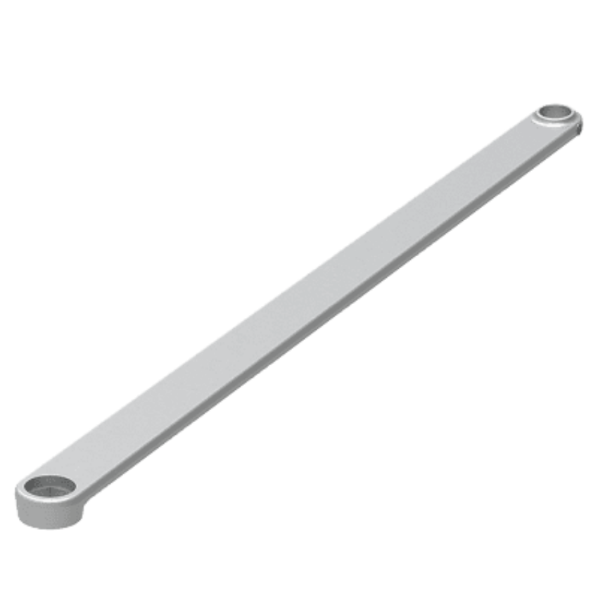
 

9475/9575 Mortise Lock Device

Von Duprin 94 95 series mortise exit device latchbolt collar part 968939 at SecurityParts.com

Von Duprin 968939 Latchbolt Collar, specific to the 9475/9575 mortise configuration. OEM part available at SecurityParts.com.


The mortise configuration integrates the 94/95 INPACT push pad mechanism with a mortise lock chassis in the door edge. This provides the highest level of security and function range in the INPACT line. The mortise device uses a different latch assembly than the CVR configuration and includes a latchbolt collar (part 968939) that is specific to the mortise application.


9475/9575 Mortise Lock Fire-Rated

The fire-rated mortise configuration adds UL 10C fire-exit hardware compliance to the mortise device. Installation on a fire-rated opening requires the device to carry the fire-exit hardware label, which is separate from the panic hardware listing. Never substitute a panic-only device on a fire-rated opening.


Von Duprin 94/95 Series Exit Device Parts: What Each Component Does

Dogging Assembly (Dog Key, Dogging Clip, Spring)

The dogging assembly holds the latch retracted for free push-pull access on non-fire-rated openings, engaged with a 5/32-inch hex dog key.

  • Part 090085 - Dog Key 5/32" Hex, Package of 10
  • Part 090005 - Dog Key 5/32" Hex, Package of 2

Dog keys are the most frequently lost component on INPACT devices. When dogging fails to hold, inspect the dogging clip spring (part 971664) and dogging clip (part 971659) first. These components are specific to the INPACT mechanism.


Latch Kits: Top and Bottom

The CVR configuration requires both a top latch kit and a bottom latch kit. These are the latch assemblies that engage the door frame strikes at the top and bottom of the door. Each kit contains the latch bolt, latch collar, and related hardware for that position.

  • Part 050492 - Top Latch Kit
  • Part 050493 - Bottom Latch Kit
  • Part 050128 - Top Latch Kit (alternate configuration)
  • Part 050495 - Bottom Latch Kit (alternate configuration)

Confirm the correct latch kit variant from the model number on the device label. If the latch bolt is not engaging the strike consistently, inspect the latch collar and compression spring (part 090066) before replacing the full kit.


Ratchet Release Kit: What It Is and When It Fails

The ratchet release kit is unique to the INPACT series and the most commonly misdiagnosed component on a failing 94/95 device. The ratchet mechanism is what allows the recessed push pad to engage the latch retraction linkage without protruding. When the ratchet release fails, the push pad either does not retract the latch at all or requires excessive force to operate.

  • Part 106222 - Ratchet Release Kit
  • Part 090070 - Ratchet Release Screw Package of 2
  • Part 090069 - Ratchet Lever Spring Package of 2

The ratchet lever spring (090069) is the highest-wear component in this assembly. On high-traffic openings, this spring fatigues before the rest of the mechanism and causes the pad to feel loose or fail to fully retract the latch. Replace the spring first before ordering the full ratchet release kit (106222), which is the complete assembly for a full rebuild.


EL Electric Latch Retraction Parts

The EL option adds electric latch retraction to the 94/95 INPACT device, enabling the door to be unlatched remotely via an access control signal. The EL components are serviceable independently of the mechanical push pad assembly.

Von Duprin 94 95 series exit device EL cable connector part 110388 at SecurityParts.com

Von Duprin 110388 EL 6' Cable Connector for the 94/95 INPACT series. Available at securityparts.com.


  • Part 110388 - EL 6' Cable, Connector
  • Part 050534 - EL Potted Circuit Breaker
  • Part 050539 - EL Receptacle Connector
  • Part 050047 - Non-EL Latch Retrofit Kit (converts EL device to non-EL)
  • Part 050048 - Non-EL Latch Retrofit Kit (alternate configuration)

The EL cable connector (110388) is the first component to check when electric latch retraction stops responding. Connector failures are more common than circuit breaker failures. The circuit breaker (050534) requires replacement after any over-voltage event.


Rod and Linkage Components

The CVR configuration includes vertical rods that run inside the door stile from the mechanism to the top and bottom latch assemblies. The rod connecting screws secure the rod joints and are a common source of CVR failures when they loosen from repeated operation.

  • Part 090071 - Rod Connecting Screw Package of 2
  • Part 090072 - Rod Connecting Screw Package of 2 (alternate)
  • Part 090107 - Control Link Pin Retaining Ring, Package of 10
  • Part 051808 - Extension Rod Kit 10'

The extension rod kit (051808) is required on oversized doors where the standard rod length does not reach the full height of the door. Confirm the door height before ordering any rod components.


Mounting and Door Prep Parts

  • Part 900856 - Wood Door Mounting Package
  • Part 090063 - Latch Link Pin Retaining Ring, Package of 10
  • Part 090064 - Latch Link Pin, Package of 10
  • Part 090065 - Bolt Return Spring, Package of 10
  • Part 109324 - Latch Mounting Bracket Kit
  • Part 112868 - Latch Mounting Bracket Kit (alternate)


INPACT Door Preparation Requirements

The 94/95 INPACT series has specific door preparation requirements that differ from standard exit devices. Understanding these before ordering any retrofit parts prevents installation errors.


Hollow Metal Door Preparation

The INPACT device requires a factory-cut door preparation on hollow metal doors. Field-modifying a standard hollow metal door is not recommended and may void the fire rating. When replacing an existing INPACT device, the replacement installs directly into the existing preparation, provided you order the same configuration and model generation.


Wood Door Installation

Wood door installations require part 900856, the Wood Door Mounting Package. This package contains the additional hardware needed to secure the mechanism to a wood door substrate. Standard hollow metal mounting hardware is not sufficient for wood door applications.


How to Identify the Right 94/95 Part Before Ordering

The 94/95 INPACT series has model generations where part numbers differ between the 9447/9547 and 9475/9575 configurations. Follow this process before placing any order:

  1. Read the model number from the device label. The label is on the mechanism case. The model number tells you the configuration (CVR or mortise) and the generation.
  2. Identify the failing component by symptom. Pad not retracting = ratchet release or spring. Latch not engaging strike = latch kit or collar. EL not responding = cable connector first, then circuit breaker. Rod not driving the latch = rod connecting screw or mounting bracket.
  3. Confirm the part number on the series page. The 94/95 series parts catalog lists all 30 stocked OEM parts. If the catalog part number matches your service manual, you have the right part.
  4. Call 845-935-0301 for compatibility confirmation on older generations before ordering.


OEM Replacement Parts for Von Duprin 94/95 Series at SecurityParts.com

SecurityParts.com stocks 30 OEM replacement parts for the Von Duprin 94/95 INPACT series, organized by component type on the 94/95 series parts catalog page. Parts include dogging keys, retaining rings, latch kits, ratchet release components, EL cable and circuit breaker, rod hardware, mounting packages, and extension rods.

All parts are OEM. Aftermarket substitutes for INPACT devices carry significant risk of dimensional incompatibility in the ratchet mechanism and latch kits. See the OEM vs aftermarket guide for detail. Common parts ship same day. Call 845-935-0301 to confirm availability on less common configurations. The full Von Duprin catalog is at securityparts.com/von-duprin. Browse all exit device parts at SecurityParts.com.


About the Author

This guide is published by the commercial door hardware team at SecurityParts.com, a supplier of OEM Von Duprin, Schlage, LCN, Falcon, and Detex parts since 2001. All part numbers, series specifications, and configuration details are verified against live SecurityParts.com product pages and official Von Duprin documentation. For Von Duprin 94/95 series part identification and same-day shipping on stocked components, call 845-935-0301 or visit the SecurityParts.com contact page.


Commercial Door Hardware for Hotels and Motels: Guest Room Locks, Communicating Doors and Panic Hardware Guide

Hotels operate across multiple occupancy types simultaneously, and the hardware requirements change floor by floor and space by space. Guest room floors are R-1 Residential occupancy: panic hardware is never required on these floors regardless of how many guests are present, because residential occupancy is not a panic-hardware-triggering occupancy type. Hotel ballrooms, meeting rooms, and restaurants are Assembly occupancy: panic hardware is required when the occupant load reaches 50 (IBC) or 100 (NFPA 101). Communicating doors between adjacent hotel rooms require 45-minute fire door assemblies in 1-hour partitions but are specifically exempted from self-closing device requirements under IBC 716.2.6 and NFPA 101, as long as they still have positive-latching hardware. The Schlage CS210 interconnected lock handles guest room entry doors with single-motion egress.

A hotel with 200 guest rooms, a ballroom, a restaurant, a pool, and a fitness center is not one building: it is four occupancy types layered on a single structure, each with distinct hardware requirements. The guest room corridor gets standard cylindrical corridor hardware. The ballroom gets Von Duprin exit devices. The communicating door between rooms 401 and 403 gets fire-rated doors without closers. Getting any one of these wrong generates inspection citations, brand standard violations, and in some cases genuine life safety failures.

Browse hotel hardware parts at SecurityParts.com: Schlage CS210 interconnected lock parts for hotel guest room entry doors, Schlage ND Series cylindrical lock parts for hotel corridor doors, Von Duprin 98/99 Series exit device parts for hotel assembly spaces, LCN door closer parts for hotel corridor and stairwell doors, and the complete Allegion hotel hardware catalog.

R-1 occupancy Hotel guest room floors: residential occupancy means panic hardware is NEVER required regardless of guest count on the floor
45 min Fire door rating required for communicating doors between hotel rooms in 1-hour fire partitions per 2021 IBC Table 716.1(2)
No closer required Communicating doors are specifically exempted from self-closing device requirements under IBC 716.2.6 Exception 1 and NFPA 101
50 vs 100 IBC panic hardware threshold (50 occupants) vs NFPA 101 threshold (100 occupants) for hotel assembly spaces: a critical difference for meeting room specification


The Hotel Hardware Challenge: Six Different Door Types in One Building

Hardware specification for a hotel must account for the full range of occupancy types within a single building. Each zone has distinct code requirements, brand standard expectations, and operational needs that cannot be served by a single hardware specification applied throughout.


Guest Room Entry Doors

R-1 residential, corridor to sleeping unit

Schlage CS210 interconnected lock (latch plus deadbolt, single-motion egress). Second security device allowance: door guard or security chain permitted under IBC/NFPA 101 residential exception. Electronic locks for key card access per brand standard.


Communicating Doors

Between adjacent sleeping units

45-minute fire door assembly in 1-hour partition. No closer required (IBC 716.2.6 Exception 1). Single-sided deadbolt with thumbturn on room side, blank plate facing other door. Active latch bolt required despite closer exemption.


Guest Floor Corridor Doors

Housekeeping, vending, laundry

Standard cylindrical or mortise locks per function. Storeroom function for housekeeping rooms. No panic hardware requirement on guest floor corridor doors. Self-closing required on fire-rated corridor doors.


Stairwell Enclosure Doors

60-min or 90-min fire rated

90-minute fire door in 2-hour enclosures. Self-closing required. Fire exit hardware on stairwells serving assembly areas at the panic threshold. Stairwell reentry hardware for buildings over 4 stories per IBC/NFPA 101.


Assembly Spaces

Ballrooms, meeting rooms, restaurants

Von Duprin exit devices required when occupant load reaches IBC threshold (50) or NFPA 101 threshold (100). Fire exit hardware on rated doors. QEL for access control between events. Exit alarms on exterior assembly exits.


Service and Back of House

Loading dock, kitchen, utility

Heavy-duty exit devices on loading dock and kitchen exits. Cylindrical storeroom function on kitchen offices. Security hinges NRP on all outswing exterior service doors. Surface-mounted closers on service corridor fire doors.


Hotel Guest Room Entry Doors: The Two-Operation Exception

Hotel guest room entry doors qualify for the same two-operation exception that applies to all residential sleeping units under IBC Section 1010.2.4(5) and NFPA 101 Section 7.2.1.5.3.4. Both codes allow one additional security device (deadbolt, night latch, door guard, or security chain) in addition to the primary latch on sleeping unit entry doors, provided the additional device is operable from inside without a key or tool.

This exception allows a hotel room door to have both a primary latch (in the lockset) and a door guard or privacy latch on the inside of the door, which is the standard hotel guest expectation. What the exception does not permit is a configuration that requires the guest to simultaneously operate both devices with two hands. The devices must be sequential, not simultaneous, for the configuration to satisfy the one-hand operability requirement of accessibility standards.


Schlage CS210 Interconnected Lock for Guest Room Entry

The CS210 is the standard specification for hotel guest room entry doors where the brand standard requires a deadbolt and latch in a single integrated hardware unit. The CS210's single inside lever rotation retracts both the latch and deadbolt simultaneously, satisfying the single-motion egress requirement from inside the room without the guest needing to operate two separate devices. From the corridor, the deadbolt requires a key (or electronic credential) to retract. Browse Schlage CS210 interconnected lock parts for hotel guest room doors at Security Parts.


Hotel Communicating Doors: The Code Requirements That Architects Get Wrong

Communicating doors between adjacent hotel sleeping rooms are one of the most frequently misspecified door types in hospitality construction. The misspecification usually goes in one of two directions: fire-rating the doors correctly but adding closers that are not required (adding cost), or omitting fire ratings because the installer thought the closer exemption also meant the fire-rating requirement was relaxed (a genuine life safety error).


How a Communicating Door Pair Works


Room 401

Thumbturn deadbolt on Room 401 side. Blank plate facing Room 403 door.

Door A (Room 401 swing)
Door B (Room 403 swing)
 

Room 403

Thumbturn deadbolt on Room 403 side. Blank plate facing Room 401 door.


Fire Rating Requirements

Under the 2021 IBC, walls separating sleeping rooms in hotels are fire partitions (Section 420.2 and 708.3) with a minimum 1-hour fire resistance rating. Per IBC Table 716.1(2), a 1-hour fire partition that is not part of a corridor or exit enclosure requires 45-minute fire door assemblies as opening protectives. This is the required fire rating for communicating doors in standard hotel construction. Exception: buildings of Type IIB, IIIB, or VB construction that are fully sprinklered may use 1/2-hour fire partitions, which require 20-minute fire door assemblies.

Both door leaves in the communicating pair are typically required to be fire-rated, even though the IBC does not prescriptively require both. Most AHJs take the position that using one rated door and one non-rated door in the same opening compromises the fire separation. The NFPA 101 Handbook states: "The requirement for a fire barrier separation between the rooms, therefore, necessitates the use of a fire protection-rated door assembly for at least one of the doors in any guest room-to-guest room opening." Many AHJs interpret this to require both doors rated, and the safe specification practice is to rate both unless the AHJ explicitly approves a single-rated configuration.


What IS Required

45-minute fire door assemblies (in 1-hour fire partitions) on both door leaves. Both doors must have active latch bolts providing positive latching engagement.

Single-sided deadbolt with thumbturn on the room side and a blank plate on the side facing the adjacent door. Both rooms must independently unlock their door to allow shared access.


What is NOT Required

Self-closing devices: IBC Section 716.2.6 Exception 1 specifically exempts communicating doors between sleeping units in Group R-1 from the self-closing or automatic-closing device requirement. NFPA 101 includes the same exemption. No door closer is required on communicating doors.

Emergency egress compliance: communicating doors are not required egress doors, so the single-operation egress requirement does not apply. Two-operation locking hardware (deadbolt plus latch) is acceptable.


The communicating door latch requirement that the closer exemption does NOT remove: IBC Section 716.2.6 Exception 1 exempts communicating doors from the self-closing requirement, not from the latching requirement. The communicating door must still have an active latch bolt that positively engages the strike when the door is in the closed position. A communicating door with only a security deadbolt and no latch bolt does not meet the fire door assembly requirement for positive latching, even with the closer exemption in effect. Both devices are needed: the deadbolt for guest security, and the latch bolt for fire door latching compliance. The Schlage CS210 interconnected lock with entry function provides both in a single unit, or a separate cylindrical passage latchset can be added alongside the security deadbolt.
 

Panic Hardware in Hotels: Where It Is and Is Not Required

The panic hardware question in hotels is one of the most frequently misunderstood topics in hospitality construction, and the misunderstanding goes both directions. Some specifications add panic hardware to guest floor corridor doors out of excessive caution. Others omit it from hotel meeting rooms that meet the assembly occupancy threshold because they assume the hotel's residential classification protects all spaces within the building. Both are wrong.


Hotel SpaceOccupancy TypeIBC Panic ThresholdNFPA 101 Panic ThresholdPanic HW Required?
Guest room floor corridorR-1 ResidentialNot applicable (R-1)Not applicable (R-1)No, never
Hotel lobbyAssembly (if locking doors)50+ occupants100+ occupantsDepends on occupant load and whether doors lock
Ballroom / banquet hallAssembly50+ occupants100+ occupantsYes, if occupant load threshold met and doors lock
Meeting roomsAssembly50+ occupants100+ occupantsDepends on calculated occupant load and adopted code
Restaurant / bar (separated)Assembly50+ occupants100+ occupantsDepends on occupant load calculation
Pool / fitness centerAssembly50+ occupants100+ occupantsDepends on occupant load; pools often have panic hardware
Stairwells (all floors)Exit enclosureAlways required if lockingAlways required if lockingFire exit hardware required on all stairwell doors
 
The IBC vs NFPA 101 panic hardware threshold difference that changes hotel meeting room specifications: The IBC requires panic hardware on Assembly occupancy egress doors at an occupant load of 50 or more. NFPA 101 sets that threshold at 100. A hotel meeting room with a calculated occupant load of 75 persons does not require panic hardware in a NFPA 101 jurisdiction, but does require it in an IBC jurisdiction. For hotel chains with properties in multiple states, brand standards typically specify to the more stringent threshold (IBC's 50-person threshold) to ensure consistency across all properties regardless of which code the local jurisdiction has adopted. Confirm the adopted code for each property location before finalizing the hardware specification.
 

Von Duprin Exit Devices for Hotel Assembly Spaces

Hotel ballrooms, banquet halls, large meeting rooms, and ground-floor restaurants that meet the panic hardware threshold require Von Duprin exit devices on all egress doors from those spaces. These are the same exit device specifications that apply to any other assembly occupancy: the hotel's residential classification on guest room floors does not carry over to the assembly spaces on the ground floor or event floor.


QEL for Event Access Control

Von Duprin QEL (Quiet Electric Latch) exit devices are specified for hotel meeting room and ballroom egress doors where the space needs to be secured between events while providing access for event setup crews and catering staff. The QEL allows the door to be locked from outside via an access control credential while keeping the push bar freely operable from inside at all times. Between events, the room is secured. During setup, authorized staff credential in. During the event, the doors remain unlocked or are set to free egress mode based on the event manager's access control programming.


Browse Von Duprin 98/99 Series and QEL exit device parts for hotel assembly spaces at Security Parts.


Hotel Hardware Specification Schedule

SetDoor LocationLockCloserEgress Hardware
H-1Guest room entrySchlage CS210 interconnected (latch + deadbolt, single-motion egress) + electronic lock per brand standardSurface closer (brand standard dependent)Standard cylindrical lever; CS210 provides single-motion egress
H-2Communicating door (each leaf)Single-sided deadbolt (thumbturn inside, blank plate facing adjacent door) + cylindrical latch boltNo closer required (IBC 716.2.6 Exception 1)Not an egress door; two-operation locking permitted
H-3Housekeeping / service roomsSchlage ND Series storeroom functionSurface closer if fire-ratedStandard lever; no panic hardware requirement
H-4Ballroom / meeting room egressVon Duprin QEL for event access control integrationLCN 4040XP (self-closing required)Von Duprin 98/99 Series exit device (panic hardware at 50+ IBC / 100+ NFPA 101)
H-5Stairwell doorsLever or fire exit hardware; reentry hardware if over 4 storiesLCN closer required (self-closing)Von Duprin fire exit hardware on fire-rated stairwell doors
H-6Loading dock / service exitCylinder trim; cylindrical storeroom on service officesSurface closerVon Duprin exit device with exit alarm (EA); NRP security hinges on outswing exterior

For parts and specification support on hotel hardware, browse Schlage ND Series cylindrical lock parts and contact SecurityParts.com at 845-935-0301 or the contact page.


Why Choose Security Parts for Hotel Door Hardware Parts

R-1 occupancy panic hardware exemption documented, communicating door latch-but-no-closer requirement, IBC vs NFPA 101 threshold difference for meeting rooms, CS210 interconnected lock, and same-day OEM shipping.


R-1 Occupancy Panic Exemption

We document the occupancy-type logic behind why guest room floors never require panic hardware: both occupant load AND triggering occupancy type must be satisfied simultaneously. R-1 residential is not a triggering type regardless of how many guests are present.


Communicating Door Latch Requirement

We document that the closer exemption on communicating doors does not remove the latching requirement. Both a security deadbolt and an active latch bolt are needed. Missing the latch bolt on a communicating door creates a fire door assembly that fails the positive latching requirement.


IBC vs NFPA 101 Threshold

We document the 50 vs 100 person panic hardware threshold difference between IBC and NFPA 101 for hotel meeting rooms. Hotel chains with multi-state properties need to understand this to set brand standards that comply everywhere.


Same-Day OEM Shipping

CS210, Von Duprin, LCN, and Schlage hotel hardware parts ship same day from US warehouses. Call 845-935-0301 or the contact page for hotel hardware support.


What Makes Security Parts Different for Hotel Hardware Parts

  • We document the specific occupancy-type logic behind hotel panic hardware requirements: both the occupant load threshold AND the triggering occupancy type (Assembly, Educational, High Hazard) must be simultaneously satisfied. A guest room floor with 200 guests never requires panic hardware because R-1 residential occupancy is not among the triggering types, regardless of the number of people present.
  • We document that the IBC 716.2.6 Exception 1 closer exemption on communicating doors does NOT remove the latching requirement. Both a security deadbolt and an active latch bolt are required on communicating doors. A communicating door with only a deadbolt and no latch bolt fails fire door positive latching requirements even though no closer is needed.
  • We document the IBC vs NFPA 101 panic hardware threshold difference for hotel meeting rooms (50 persons vs 100 persons) and its specific implication for multi-state hotel chains: a meeting room that does not require panic hardware under NFPA 101 does require it under the IBC, meaning brand standards set to the more stringent threshold ensure compliance across all properties.
  • We document the communicating door AHJ interpretation standard: while the NFPA 101 Handbook states that at least one door in the communicating pair must be fire-rated, most AHJs require both, and the safe specification practice is to rate both unless the AHJ explicitly approves a single-rated configuration.
  • We carry Schlage CS210 interconnected lock parts, Von Duprin exit device and QEL parts, LCN door closer parts, and Schlage ND Series cylindrical lock parts for all hotel hardware zones.
  • Free shipping on orders over $450. Same-day shipping from US warehouses on stocked parts. 30-plus years of commercial door hardware experience.


Frequently Asked Questions About Hotel Door Hardware


Why is panic hardware not required on hotel guest room corridor doors?

Hotel guest room floors are classified as Group R-1 Residential occupancy under the IBC and as hotel/motel occupancy under NFPA 101. Panic hardware requirements apply specifically to Assembly, Educational, and High Hazard occupancies at defined occupant load thresholds. Residential occupancy is not among the triggering types regardless of the number of guests on the floor. A 200-guest hotel floor does not require panic hardware because R-1 residential fails the occupancy-type test, even though the occupant load is above the threshold. Both occupant load AND occupancy type must simultaneously trigger to create a panic hardware requirement.


What is a communicating door between hotel rooms and what hardware does it require?

A communicating door is a pair of doors in a single frame within the wall separating two adjacent sleeping rooms. The 2021 IBC requires 45-minute fire door assemblies in 1-hour fire partitions (Table 716.1(2)). Both door leaves are typically required to be fire-rated by most AHJs. Security hardware is a single-sided deadbolt with thumbturn on the room side and blank plate facing the adjacent door, requiring both guests to unlock their respective door for passage. An active latch bolt on each door is also required for positive latching compliance, even though a door closer is not required.


Why are hotel communicating doors not required to be self-closing?

IBC Section 716.2.6 Exception 1 specifically exempts communicating doors between sleeping units in Group R-1 from the self-closing or automatic-closing device requirement. NFPA 80 and NFPA 101 include the same exemption. The rationale is that when both communicating doors are simultaneously open, the two rooms function as a suite, making a fire separation unnecessary. The exemption applies only to the closer, not to the latch: communicating doors must still have active latch bolts providing positive latching when closed.


When is panic hardware required in a hotel ballroom or meeting room?

Hotel ballrooms and meeting rooms are Assembly occupancy regardless of the hotel's overall R-1 classification. IBC requires panic hardware on Assembly occupancy egress doors at 50 or more occupants. NFPA 101 sets the threshold at 100. The requirement applies only to doors equipped with a lock or latch: unlocked push/pull doors do not trigger panic hardware. Hotel meeting rooms below the threshold can use standard cylindrical hardware. Above the threshold, Von Duprin exit devices are required on all egress doors from that space.


What is the Schlage CS210 interconnected lock used for in hotels?

The CS210 is specified for hotel guest room entry doors where both a deadbolt and latch are required in a single integrated unit with single-motion egress from inside. A single rotation of the inside lever simultaneously retracts both the latch bolt and the deadbolt, satisfying egress requirements. From the corridor, key or electronic credential operation is required for entry. It is a Grade 2 product, appropriate for hotel guest room applications, and directly replaces the discontinued Schlage S200 Series on most existing installations.


What Von Duprin exit devices are specified for hotel assembly spaces?

Von Duprin 98/99 Series for standard hotel ballroom and meeting room egress doors above the panic hardware threshold. QEL (Quiet Electric Latch) for event access control: allows the room to be secured between events while providing credential-based entry for setup crews. Exit alarm (EA) versions for exterior assembly exits and service exits where unauthorized use between events is a concern. Fire exit hardware (UL 10C listed) on any fire-rated egress door where panic hardware is required. NRP security hinges on all outswing exterior exit doors from assembly spaces.

Commercial Security Hardware Guide: Types, Functions, and OEM Replacement Parts

Every commercial building relies on a coordinated system of commercial security hardware to control access, protect occupants, and meet code requirements. When one component fails, it affects the entire opening. Understanding what each type of hardware does, how the pieces work together, and where to find the right OEM replacement part is essential for facility managers, contractors, and building owners who maintain commercial properties.

This guide covers the major categories of commercial door security hardware, explains what each one does on a real opening, and connects you directly to OEM replacement parts at SecurityParts.com. For part identification and ordering reference by hardware type, see the companion security door parts guide.


Quick Answer 

  • Commercial security hardware includes exit devices, mortise locks, cylindrical locks, door closers, electric strikes, deadbolts, and access control hardware. Each serves a distinct function on a commercial opening.
  • Most hardware is rated by ANSI Grade (Grade 1 = commercial/highest, Grade 2 = residential, Grade 3 = light duty). Always replace commercial hardware with the same grade or higher.
  • New installation and maintenance are different tasks. New installation means specifying a complete hardware package. Maintenance means identifying the exact failed component and ordering the correct OEM replacement part for the installed model.
  • On most commercial openings, multiple hardware categories work together: a lock controls access, an exit device handles egress, a door closer controls the swing, and an electric strike or deadbolt provides the final locking point.
  • SecurityParts.com stocks OEM replacement parts for Schlage, Von Duprin, LCN, Falcon, and Detex. Browse the full parts catalog.


What Is Commercial Security Hardware

Commercial security hardware refers to the mechanical and electromechanical devices installed on commercial doors to control access, provide safe egress, and meet code requirements. It is distinct from residential hardware in three ways: it is built to higher durability standards, tested to ANSI grade classifications, and required to meet life safety codes that residential hardware is not.

In a commercial building, the hardware on any single door opening may include several devices: a lock, an exit device, a door closer, a strike plate or electric strike, and in access-controlled environments, electrified hardware connected to a credential reader. Every device is interdependent. A failed door closer puts mechanical stress on the lock. A misaligned strike plate causes bolt wear. Understanding the full system prevents misdiagnosis and wrong-part orders.


ANSI Grading: The Standard That Defines Commercial Hardware

The American National Standards Institute (ANSI), in collaboration with the Builders Hardware Manufacturers Association (BHMA), sets performance grades for commercial door hardware. These grades appear on every specification sheet and every product listing.

  • Grade 1: The commercial standard. The highest level of durability, security, and cycle testing. Required on most exterior commercial doors and any opening subject to high daily use.
  • Grade 2: The residential standard. Suitable for light commercial applications and interior doors with lower traffic.
  • Grade 3: The minimum grade. Appropriate only for very low-use interior applications.

When replacing hardware on an existing commercial opening, always match or exceed the installed grade. Downgrading from Grade 1 to Grade 2 on a high-use door creates a performance and liability gap. For a full breakdown of ANSI/BHMA grading across all hardware categories, see the ANSI/BHMA door hardware standards guide.


Exit Devices: Commercial Egress Hardware

Von Duprin 98/99 series exit device commercial panic hardware at SecurityParts.com

Von Duprin 98/99 series rim exit devices. One of the most widely installed exit device lines in commercial buildings. OEM replacement parts available at SecurityParts.com.

Exit devices, also called panic hardware or push bars, are the push-bar mechanisms installed on outswing doors that must allow emergency egress without any special knowledge or key. A single downward or horizontal push on the bar releases the door latch. This is a life-safety requirement on most commercial exit doors, codified under NFPA 101 and IBC requirements.

Exit devices are required on doors serving assembly occupancies, educational buildings, healthcare facilities, and any space with an occupant load above a set threshold defined by the local building code. They are also the most commonly maintained devices in commercial buildings because their frequency of use is high and they take significant mechanical stress.


Types of Exit Devices

Rim Exit Devices

Surface-mounted to the face of the door. The most common configuration on single exterior doors and the active leaf of double doors. Simple to service because all components are accessible without removing the device from the door. Von Duprin's 98/99 and 9800/9900 series are the industry standard.


Surface Vertical Rod (SVR) Exit Devices

Use vertical rods that run along the door surface to shoot bolts at the top and bottom of the door frame, instead of a rim strike. Used on double doors without a center mullion where rim devices on both leaves would conflict. Rods are exposed on the door surface.


Concealed Vertical Rod (CVR) Exit Devices

Operate the same way as SVR devices but the vertical rods run inside the door stile. Preferred where aesthetics matter and exposed rods are undesirable. Requires a mortised door preparation.


Mortise Exit Devices

Integrate the exit device function with a mortise lock chassis. Provide the highest security and function flexibility. Common on high-security openings where both panic egress and robust access control are required on the same door.

For replacement parts across all exit device types, see the exit devices parts guide and the Von Duprin parts catalog. For help selecting the right exit device configuration, see the panic bar selection guide.


Mortise Locks: High-Security Commercial Locksets

A mortise lock installs inside a pocket (the mortise) cut into the door edge. The entire lock chassis, including the latch, deadbolt function, and cylinder housing, is contained within the door. This design makes mortise locks significantly more resistant to forced entry than surface-mounted lock configurations.

Mortise locks are the standard on high-security commercial openings: hospital corridor doors, educational building exteriors, government facilities, and institutional buildings. The Schlage L-Series is the most widely installed Grade 1 mortise lock in North American commercial construction.


Why Mortise Locks Are Used in Commercial Buildings

  • The lock chassis is fully enclosed within the door, eliminating exposed fasteners that surface-mounted locks present
  • Supports a wide range of ANSI function codes, allowing a single platform to serve many different access control needs
  • Cylinders, trim, and strike plates are independently replaceable without removing the lock case from the door
  • Compatible with interchangeable core (IC) key systems, enabling rapid rekeying across large facilities

For mortise lock component identification and parts, see the mortise lock parts guide and the full commercial mortise locks guide. For a direct comparison between mortise and cylindrical lock platforms, see mortise locks vs cylindrical locks.


Cylindrical Locks: The Standard Commercial Lockset

Schlage ND Series commercial cylindrical lock hardware at SecurityParts.com

Schlage ND Series commercial cylindrical locks. A Grade 1 cylindrical lockset used across offices, classrooms, and interior corridors. OEM replacement parts available through the cylindrical locks catalog at SecurityParts.com.


Cylindrical locks install through two bored holes in the door face and edge. They are faster to install than mortise locks and are the standard for interior commercial doors, office suites, classrooms, storage rooms, and any opening that does not require the full function range of a mortise lock.

A cylindrical lock consists of the exterior trim (cylinder and lever or knob), the interior trim (lever, knob, or thumb turn), the chassis (which contains the latch and function mechanism), and the strike plate. Each component is independently serviceable.


ANSI Functions for Cylindrical Locks

Cylindrical locks are available in standardized ANSI function codes that define how the lock behaves from each side of the door. Common commercial functions include:

  • Passage: Free passage from both sides. No locking function.
  • Privacy: Push-button lock from inside. No key override. Common on single-occupancy restrooms.
  • Storeroom: Always locked from outside, always free egress from inside. Key required for entry.
  • Classroom: Interior lever always free. Outside lever locked by key from outside, without entering the room. The standard for school classroom doors.
  • Entrance: Thumb turn on inside controls outside lever. Key can also lock or unlock from outside.

For cylindrical lock component identification and replacement parts, see the cylindrical lock parts guide.


Door Closers: Controlled Closing for Every Commercial Opening

LCN 4000 series commercial door closer parts at SecurityParts.com

LCN 4000 Series surface-mounted commercial door closers. One of the most widely installed commercial closer lines in North America. OEM replacement parts available at SecurityParts.com.


A door closer is a hydraulic device that controls the speed and force with which a door closes. On any fire-rated door, a closer is mandatory: the door must close and latch automatically after every use to maintain the fire rating. On non-fire-rated doors, closers prevent door slamming, reduce wear on the lock and frame, and are required on ADA-compliant openings where the closing force must not exceed a specified resistance.


Types of Commercial Door Closers

Surface-Mounted Closers

Mounted on the surface of the door or frame. Visible hardware. The most common type in commercial buildings because they are easy to install, adjust, and service without removing the door from its hinges. LCN's 1000 and 4000 series are industry standards.


Concealed Closers

Installed inside the door or frame, invisible from the outside. Used where aesthetics are a priority and exposed hardware would be undesirable. Require specialized door preparation.


Electromechanical Closers and Hold-Open Devices

Surface-mounted closers with an electromagnetic hold-open function. The door is held open by the magnet and closes automatically when the fire alarm triggers, releasing the magnetic hold. Required in fire-exit corridors where free passage is needed during normal operation but the door must close on alarm activation.

For door closer component identification and replacement parts, see the door closers parts guide and the LCN door closer parts guide.


Electric Strikes: Electrified Locking for Access Control

An electric strike replaces the standard mechanical strike plate in the door frame. The strike has a moving keeper that, when electrically released, allows the latch bolt to pass through even though the lock lever is in the locked position. This enables a door to be unlocked remotely via a card reader, keypad, or intercom without modifying the lockset itself.

Electric strikes are one of the most common methods of integrating existing mechanical hardware into an access control system because they work with most cylindrical locks, mortise locks, and exit devices without changing the door or lock preparation.


Fail-Safe vs Fail-Secure Electric Strikes

This is the most important specification decision when selecting or replacing an electric strike:

  • Fail-safe: The strike releases (unlocks) when power is lost. Used on egress doors where the door must be openable during a power outage or fire alarm, when the building's fire alarm system typically cuts power to all access-controlled doors.
  • Fail-secure: The strike remains locked when power is lost. Used on high-security openings where unauthorized access during a power event is the greater risk.

The fail-safe or fail-secure decision is a life-safety consideration and must align with the building's fire alarm integration and local code requirements. Never substitute one for the other without verifying code compliance.

For electric strike component identification and OEM replacement parts, see the electric strike parts guide.


Deadbolts: Secondary Locking for Commercial Openings

A deadbolt provides a secondary locking point that is independent of the primary latch. Unlike a spring latch, a deadbolt cannot be retracted without deliberate action: turning a key from outside or operating a thumb turn from inside. The bolt is solid steel and engages a reinforced strike plate in the door frame.

In commercial buildings, deadbolts are used on exterior office doors, storage rooms, server rooms, and any opening where the primary cylindrical lock function alone is not sufficient security. They are also used in classroom deadbolt configurations (such as the Schlage B663) where the outside lever is always locked and the deadbolt is operated from inside to secure the room during a lockdown.

For deadbolt component identification and replacement parts, see the deadbolt parts guide.


Panic Hardware and Exit Alarms: Controlled Egress Devices

Beyond standard exit devices, two specialized categories address situations where egress must be monitored or delayed:

Alarmed Exit Devices

Exit devices equipped with a local battery-powered alarm that sounds when the door is pushed open without being disarmed. Used on secondary exit doors in retail stores, warehouses, and educational buildings where the door should only be used in emergencies. The Detex alarm exit hardware line is the standard for this application in North American commercial buildings.

For Detex alarm hardware parts, see the exit alarms parts and diagrams guide. Browse Detex parts at SecurityParts.com.


Delayed Egress Devices (Chexit)

Delayed egress devices are exit devices with a timed delay that sounds a local alarm and holds the door for a set period (typically 15 seconds) before releasing. They are used in memory care facilities, psychiatric units, and retail locations where unauthorized egress is a safety or loss-prevention concern. NFPA 101 regulates where delayed egress is permitted.

Von Duprin's Chexit option is the standard delayed egress modification for the 98/99 series exit device. For Chexit parts, see the Von Duprin 98/99 series parts guide.

For a broader overview of panic hardware applications and code requirements, see the panic hardware for commercial doors guide.


Electrified Hardware: Integrating Mechanical Locks with Access Control

Electrified hardware refers to mechanical door hardware that has been modified or designed to operate under electrical control. It is the bridge between traditional locksets and modern access control systems. A door can be mechanically sound and electrically controllable at the same time.


Common Electrified Hardware Types

Electric Latch Retraction (EL)

Allows the latch bolt on an exit device or mortise lock to retract electrically, enabling the door to swing open without mechanical operation of the push bar. Used on high-traffic controlled entries where doors must release remotely on demand.


Electrified Trim

Outside lever assemblies on mortise locks that can be electrically locked or unlocked while maintaining free egress from the inside. The credential is presented outside, power is applied or cut to the trim, and the lever operates or remains locked accordingly.


Motorized Latch Retraction

A motor-driven mechanism that retracts the latch bolt via an electrical signal. Used on high-security or high-traffic applications where consistent, mechanical-free operation is required. Schlage's L9580 motorized latch retraction is an example of this configuration.

For guidance on integrating electrified hardware with access control systems, see the access control and commercial door hardware integration guide.


How Hardware Categories Work Together on a Single Opening

On most commercial exit doors, several hardware categories are installed on the same opening and interact with each other. Understanding these relationships prevents misdiagnosis when something fails.

A typical controlled exit opening in a commercial building has:

  • An exit device on the interior that provides panic egress
  • An electric strike in the frame that provides the electronic locking point from outside
  • A door closer at the top of the door that ensures the door closes and latches after every use
  • An outside trim lever connected to the exit device that allows keyed entry from outside
  • A credential reader that signals the electric strike to release on valid access

When a symptom appears, the question is always: which component in this chain has failed? A door that will not latch could be a misaligned strike (frame issue), a worn latch (exit device issue), or a closer that is not pulling the door all the way shut (closer issue). The hardware category determines which parts to inspect and which replacement parts to order.

For systematic troubleshooting across all hardware categories on a commercial opening, see the commercial door hardware troubleshooting guide.
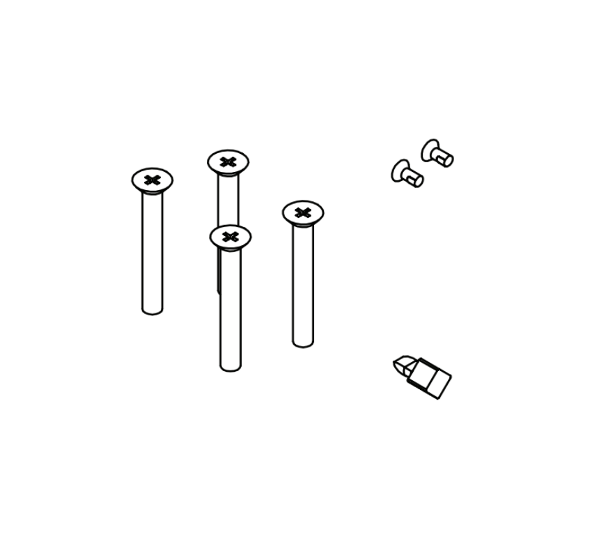
 

New Installation vs Maintenance and Replacement

This distinction matters because it determines what you need to order and where to source it.

New Installation: Full Hardware Specification

Specifying hardware for a new commercial opening means selecting a complete hardware set: the lock function, the manufacturer, the finish, the handing, the grade, the closer type, and any electrification required. Every component is new and must be coordinated to work together. This is typically done by an architectural hardware consultant or a contractor working from a project hardware schedule.


Maintenance and Replacement: Component-Level OEM Parts

Maintaining existing installed hardware means identifying exactly which component has failed and ordering the correct OEM replacement part for the specific model installed. This is a different task from new specification. The lock case, the door preparation, and the surrounding hardware are already in place. Only the failed component is replaced.

This is SecurityParts.com's specialty. Whether the failed component is a dogging shaft on a Von Duprin exit device, a cylinder assembly on an LCN closer, a latch bolt on a Schlage mortise lock, or an electric box assembly on a Von Duprin electric strike, OEM parts are available by model and part number.

OEM parts are the correct choice for commercial hardware maintenance. Aftermarket substitutes may not meet the same tolerances, cycle ratings, or finish specifications as the original. For a detailed comparison, see the OEM vs aftermarket commercial door hardware parts guide.
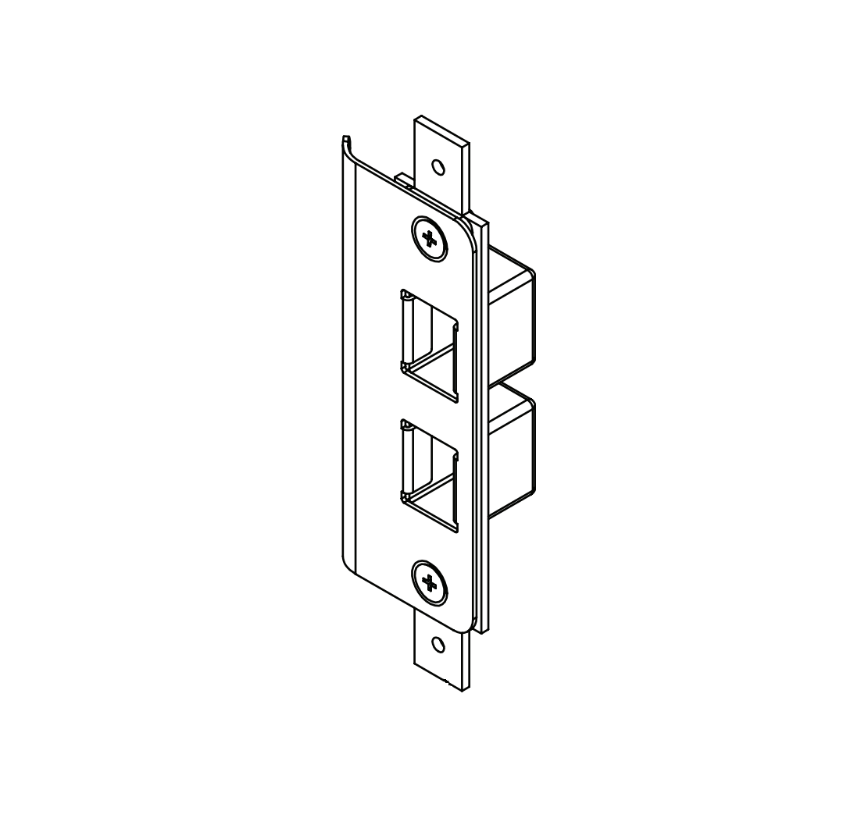
 

How to Identify the Right OEM Replacement Part

Ordering the wrong part is the most common and most avoidable error in commercial hardware maintenance. The correct identification process follows the same three steps regardless of hardware category:

  1. Identify the manufacturer and model. The manufacturer name and model number are stamped on the device body, the cylinder face, or the closer arm. Never order by description alone. A "Von Duprin rim exit device" includes dozens of models with different part numbers.
  2. Identify the failed component by its function. Does the bolt not retract? That is a different component from a bolt that retracts but does not throw. Symptoms point to specific components. Comparing the symptom to the parts diagram for that model narrows the search.
  3. Confirm the part number before ordering. Every model page on SecurityParts.com includes the part number, a description, and compatibility information. Confirm the part number matches the installed model before adding to cart. If unsure, call 845-935-0301.

For a detailed guide to part identification by hardware category, see the security door parts guide.
 

Hardware Finishes on Commercial Openings

Commercial security hardware is available in a range of ANSI standard finishes. The finish code matters for replacement orders because the new part must match the existing installation visually and in corrosion resistance. Common commercial finishes include US26D (satin chrome), US10B (dark bronze), US32D (satin stainless), and US28 (satin aluminum).

For a full finish code reference and matching guidance across all hardware types, see the commercial door hardware finish guide.
 

Maintenance Schedules for Commercial Security Hardware

Commercial security hardware is designed for thousands of daily cycles, but it requires periodic maintenance to reach its rated lifespan. Deferred maintenance on a single component accelerates wear across every other component on the same opening.

The key maintenance intervals for commercial hardware:

  • Every 6 months: Lubricate cylinder keyways with graphite or dry PTFE. Check door closer fluid. Verify latch engagement with the strike plate.
  • Annually: Tighten all mounting fasteners. Check closer spring tension and adjust sweep and latch speeds. Inspect exit device push bar for play. Verify electric strike keeper operation.
  • After any forced entry attempt: Inspect every component before returning the opening to service. Micro-fractures in bolts and frames are not always visible but will fail under subsequent loading.

For a complete, printable maintenance schedule organized by hardware category, see the commercial door hardware maintenance checklist.


OEM Replacement Parts for Commercial Security Hardware at SecurityParts.com

SecurityParts.com has supplied OEM commercial door hardware parts since 2001. The catalog covers Schlage, Von Duprin, LCN, Falcon, and Detex, organized by brand, model, and part number. Whether you need a replacement cylinder assembly for an LCN closer, a new push bar for a Von Duprin exit device, an electric box assembly for an electric strike, or trim components for a Schlage L-Series mortise lock, parts are available by the model-specific part number with same-day shipping on stocked components.

For pre-order part identification assistance and same-day shipping availability, call 845-935-0301 or visit the SecurityParts.com contact page.


About the Author

This guide is published by the commercial door hardware team at SecurityParts.com, a supplier of OEM Schlage, Von Duprin, LCN, Falcon, and Detex parts since 2001. All hardware specifications, ANSI grade descriptions, and product references are verified against live SecurityParts.com product pages and manufacturer documentation. For part identification and same-day shipping on stocked OEM components, call 845-935-0301 or visit the SecurityParts.com contact page.

Commercial Door Hardware for Government Buildings: GSA Standards, Schlage Primus XP and High Security Cylinders Guide

Government buildings are classified by the GSA Interagency Security Committee (ISC) Facility Security Level (FSL I through V) framework, which determines the required level of protection for door hardware and access control. FSL II buildings require key or PACS access at entrances and UL 437 high security cylinders on utility, mechanical, and electrical rooms. FSL III and above require progressive access control integration. The Schlage Primus XP is the standard high security cylinder for government applications: it adds a second independent sidebar and five finger pins to the standard pin tumbler, providing pick resistance, bump key resistance, and factory-controlled geographic exclusivity at five levels. PIV (Personal Identity Verification) credentials are required for PACS in federal buildings at FSL II and above. The ABA (Architectural Barriers Act) applies to federal buildings, not the ADA, though both have nearly identical hardware requirements.

Government buildings operate under layers of federal security standards that most commercial buildings never encounter. The GSA Interagency Security Committee framework, HSPD-12 PIV credential requirements, and the specific cylinder security requirements that flow from the FSL determination all point to hardware specifications that go significantly beyond standard commercial Grade 1 products. Understanding which standards apply and what hardware they require prevents the specification errors that delay government projects and create security compliance gaps.

Browse government-grade hardware parts at SecurityParts.com: Schlage ND Series cylindrical lock parts for government Primus XP applications, Schlage L Series mortise lock parts for government buildings, Schlage Primus XP and Everest 29 high security cylinder parts, Von Duprin exit device parts for government building egress, and the complete Allegion government hardware catalog.

April 19, 1995 Oklahoma City Murrah Federal Building bombing: the historical event that directly created the ISC federal facility security standard through Executive Order 12977
UL 437 High security cylinder listing required for utility, mechanical, and electrical rooms at GSA FSL II buildings and critical areas at higher FSL buildings
5 levels Schlage Primus XP geographic exclusivity levels from local stock (Level 1) to national exclusive (Level 5: no other US customer shares the same side bitting)
ABA, not ADA Federal buildings are governed by the Architectural Barriers Act (1968), enforced by the Access Board, not the ADA which applies to state, local, and commercial buildings


The Oklahoma City Bombing and the Creation of Federal Facility Security Standards

The April 19, 1995 bombing of the Alfred P. Murrah Federal Building in Oklahoma City, Oklahoma, killed 168 people and injured hundreds more. It was the deadliest domestic terrorist attack on a federal facility in US history at that time. A truck packed with explosives was detonated in the parking area adjacent to the building, and the resulting blast destroyed a significant portion of the structure.

In direct response, President Clinton signed Executive Order 12977 in October 1995, establishing the Interagency Security Committee (ISC). The ISC was charged with developing and implementing security standards, policies, and best practices for non-military federal facilities. The Oklahoma City bombing is explicitly referenced in the preamble of the ISC Risk Management Process as the foundational event for the current federal facility security framework. Every GSA building security requirement for door hardware, access control, PACS integration, and physical cylinder specifications flows from the regulatory structure that the Oklahoma City bombing created.


The GSA Facility Security Level Framework

The GSA Interagency Security Committee (ISC) classifies federal facilities from FSL I (lowest risk) through FSL V (highest risk). The FSL determination is based on five factors: mission criticality, symbolism (public perception and visibility of the agency), threat to tenants, population (number of employees and public), and size. The FSL then determines the required countermeasures for the facility, including door hardware and access control specifications.


ILowest

Small offices, low public access, non-critical missions. Basic mechanical locks. Conventional keyway cylinders acceptable.


IILow

Medium offices, some public access. Key or PACS for entrances. UL 437 cylinders required for utility, mechanical, and electrical rooms.


IIIMedium

Larger facilities, significant public access or mission sensitivity. PACS with card access. High security cylinders for non-public areas. PIV-compliant readers at entrances.


IVHigh

High mission criticality, law enforcement or judicial functions, or significant symbolic value. Enhanced PACS, multi-factor authentication, reinforced hardware. Primus XP high security cylinders standard throughout.


VHighest

Critical missions requiring maximum protection. Highest-grade hardware, national-exclusivity key systems, biometric and PIV multi-factor PACS. Restricted access throughout entire facility perimeter.


The FSL determination error that produces non-compliant government project specifications: The FSL for a federal facility is not determined by the specifier or the contractor: it is determined by the occupant agency and the Facility Security Committee (FSC) for multi-tenant buildings, following the ISC Risk Management Process. Hardware specifications must be based on the FSL determination produced by this process, not on the specifier's assessment of the building type or the contractor's assumption about what government buildings require. Specifying FSL II-level hardware in a building that the FSC has determined is FSL IV creates a compliance gap that becomes visible during GSA security audits.
 

UL 437 High Security Cylinder: What the Listing Actually Certifies

UL 437 is the Underwriters Laboratories Standard for Safety for Burglary Resistant Locks. A UL 437 listing certifies that the cylinder has been independently tested and confirmed to resist specific physical attack methods, including picking, drilling, sawing, pulling, wrenching, and extreme key manipulation. The certification is not a manufacturer's claim: it is a documented test result from an independent laboratory.

The GSA FSL II security requirements document specifies: "Utility, mechanical, electrical, and telecom rooms shall be secured with high-security (UL 437) locks." This requirement flows directly from the risk that these rooms represent: a compromised mechanical room allows an adversary to disable building systems, and a compromised electrical room can be used to stage attacks on the facility's power and security infrastructure. High security cylinders on these rooms are the minimum standard for FSL II and represent the baseline across all higher FSL levels.


UL 437 vs Standard Grade 1: The Specific Test Differences

ANSI/BHMA A156.5 Grade 1 is the commercial standard for quality and durability in mechanical cylinders. UL 437 is a separate standard specifically for security against physical attack. A cylinder can be ANSI/BHMA Grade 1 (durable and functional for commercial use) without being UL 437 listed (tested for attack resistance). For government buildings at FSL II and above, Grade 1 alone is not sufficient for critical area cylinders. The hardware must specifically carry the UL 437 listing. Browse Schlage Primus XP UL 437 listed cylinder parts at Security Parts.


Schlage Primus XP: The High Security Cylinder Standard for Government Buildings

The Schlage Primus XP is the government-grade upgrade that adds a second, independent locking mechanism to any Schlage cylinder format, providing security properties that standard pin tumbler cylinders cannot offer regardless of their ANSI grade.


Standard Schlage Cylinder

Single pin tumbler mechanism only
 

Mechanism: Six pin tumbler pairs. The correct key lifts each pin pair to the shear line, allowing the plug to rotate.


Pick vulnerability: A skilled picker can manipulate the pin pairs one at a time to the shear line without a key. Single tension wrench and pick tool.


Bump key vulnerability: An impact key struck sharply causes pins to momentarily jump, crossing the shear line. Bump keys can open standard cylinders with minimal skill.


Duplication control: Standard keyway blanks available commercially. Keys can be cut by any locksmith with the correct blank.


Schlage Primus XP Cylinder

Dual mechanism: pin tumbler + independent sidebar
 

Mechanism: Standard six pin tumbler plus a second independent sidebar with five finger pins. The Primus XP key has both standard top cuts and factory-milled side bitting. Both mechanisms must be simultaneously satisfied for the plug to rotate.


Pick resistance: Picking the pin tumbler to the shear line does not release the sidebar finger pins. The sidebar mechanism remains locked even when pin tumbler picking is successful, preventing plug rotation.


Bump key resistance: Impact force does not affect the sidebar finger pins, which require precise depth engagement from the factory side bitting, not impact force. Bump keys are ineffective against the Primus XP sidebar.


Duplication control: The side bitting is factory-milled only, using tooling controlled by Allegion. Key blanks are not available through commercial distribution. Geographic exclusivity at five levels prevents key sharing across the customer base.


Primus XP Backward Compatibility: The Transition Advantage

A critical operational advantage of the Primus XP system is backward compatibility: Primus XP keys operate both Primus XP high security cylinders and standard (non-Primus) Schlage cylinders on the same keyway family. This means a government facility transitioning from standard Schlage cylinders to Primus XP can replace cylinders progressively, starting with the highest-security areas, while issuing Primus XP keys that continue to operate the remaining standard cylinders already installed. No lock-out event occurs during transition, and the complete key system does not need to be replaced simultaneously.

Browse Schlage Primus XP cylinder and high security key system parts at Security Parts.


The Five Schlage Primus Geographic Exclusivity Levels

  • Level 1
    Side bitting available from local stock. Multiple customers in the same area may share the combination. Not recommended for government applications where key uniqueness is a security requirement. Standard Primus, not Primus XP exclusivity.
  • Level 2
    Side bitting restricted to customers within a designated metro area or region. Some sharing of combinations within the region is possible. Acceptable for low-risk government facilities where the main benefit is pick and bump resistance, not combination exclusivity.
  • Level 3
    Side bitting restricted to customers within a defined geographic territory. Fewer shared combinations. The combination is allocated to a smaller customer pool, reducing the probability that another organization's key could incidentally operate the cylinder.
  • Level 4
    Side bitting allocated to a single customer region with strict ordering controls. Significantly reduced sharing. Appropriate for medium-high security government applications where geographic key exclusivity is part of the security specification.
  • Level 5 (National)
    The side bitting combination is exclusive to a single end user at the national level. No other Allegion customer anywhere in the United States uses the same side bitting combination. The physical Primus XP key is unique to that agency or facility. This is the correct specification for FSL IV and V federal facilities where key system uniqueness is part of the threat countermeasure design.
 
The Primus XP side bitting factory control mechanism that makes unauthorized duplication a federal crime: Primus XP side bitting is milled exclusively at the Schlage factory using proprietary tooling. Key blanks with pre-milled Primus side bitting are not available through commercial distribution. Any attempt to duplicate a Primus XP key through reverse engineering or tooling modification produces a key that does not correctly engage the five sidebar finger pins, because the side bit depths require factory precision not achievable with field equipment. Beyond the mechanical barrier, Primus XP keys are covered by patents that make unauthorized duplication a patent infringement violation enforceable under federal law. The combination of physical impossibility with standard tools and federal patent protection creates two independent barriers against key duplication.


PIV Credentials and PACS in Federal Buildings

Homeland Security Presidential Directive 12 (HSPD-12), signed in August 2004, mandated a common identification standard for all federal employees and contractors accessing federal facilities. FIPS 201 (Federal Information Processing Standard Publication 201) defines the Personal Identity Verification (PIV) credential: a smart card carrying a digital photograph, biographic data, fingerprint biometrics, and cryptographic keys on an embedded chip.

For physical access control, PACS at FSL II and above must accept PIV credential authentication. This means the card reader at the door must read the PIV chip's cryptographic credentials and validate them electronically, not just read a card number from a magnetic stripe or proximity antenna. GSA maintains an Approved Products List (APL) for PACS components including card readers, control panels, and credential management systems. Only APL-listed products may be installed in GSA-controlled PACS systems.


PIV vs Standard Proximity Card: The Authentication Difference

A standard HID 125 kHz proximity card reader reads a facility code and card number from the card's antenna. The card contains no cryptographic content and cannot verify that the card presented is the genuine card assigned to that employee. A card can be cloned by reading its broadcast data with a covert reader. A PIV card reader reads the chip's cryptographic certificate and validates the digital signature against a trusted root. The card cannot be cloned because the private cryptographic key is stored on the chip and never leaves it. For government facilities where credential cloning is a threat, standard proximity cards do not satisfy the HSPD-12 PIV requirement regardless of the PACS platform in use.


Hardware Requirements by Government Building Zone

Area / ZoneMinimum CylinderAccess ControlExit HardwareKey Products
Public building entry (FSL II-III)Conventional restricted keyway (Everest 29 R)PACS with card access; PIV-compliant reader at FSL II+Von Duprin exit device with QEL for access control integrationVon Duprin exit device parts
Utility, mechanical, electrical rooms (FSL II+)UL 437 high security (Primus XP)Keyed access with UL 437 cylinder; no public accessStandard self-closing with positive latch; fire-rated per wall ratingSchlage Primus XP cylinder parts
Secure/sensitive offices (FSL III-IV)Primus XP Level 4-5 geographic exclusivityPACS with PIV multi-factor; audit trail requiredVon Duprin with cylindrical trim; no dogging on exterior exitsSchlage ND Series cylindrical lock parts
General office (FSL II-III)Everest 29 R restricted keyway; Primus XP optionalMechanical key or PACS depending on FSL and occupancyStandard cylindrical or mortise office functionSchlage L Series mortise lock parts
Emergency exit (all FSL levels)Exit device cylinder in restricted keywayExit alarm or monitored exit device; dogging key controlVon Duprin 98/99 Series fire exit hardware on fire-rated doorsVon Duprin 98/99 exit device parts


ABA vs ADA: Which Accessibility Law Applies to Federal Buildings

The ADA (Americans with Disabilities Act) applies to state and local government facilities, commercial establishments, and public accommodations. Federal government buildings are governed by the ABA (Architectural Barriers Act of 1968), which predates the ADA by 22 years. The ABA is enforced by the United States Access Board, which publishes the ABA Accessibility Standards.

The practical hardware specification difference is almost nil: the ADA Accessibility Standards and the ABA Accessibility Standards contain nearly identical technical requirements for door hardware. Lever handles operable with one hand, maximum 5 pounds opening force on interior doors, hardware mounted between 34 and 48 inches above the finished floor. The distinction matters in two contexts: compliance documentation (federal building projects must cite ABA compliance, not ADA compliance, in their project documentation) and enforcement (ABA violations are filed with the Access Board, not through the ADA enforcement mechanism). A federal contractor or facilities manager who documents door hardware compliance by reference to ADA rather than ABA is citing the wrong legal authority, even though the technical requirements produce the same specification result.

For parts support and specification assistance for government hardware projects, contact SecurityParts.com at 845-935-0301 or the  contact page.


Why Choose Security Parts for Government Building Hardware Parts

Oklahoma City ISC origin documented, FSL II UL 437 utility room requirement specified, Primus XP dual mechanism explained, Level 5 national exclusivity, ABA vs ADA distinction, and same-day OEM shipping.


Oklahoma City ISC Origin

We document the Oklahoma City bombing as the historical event that directly created the ISC security framework through Executive Order 12977. Understanding why the standard exists explains the urgency behind FSL compliance documentation requirements.


Primus XP Dual Mechanism

We explain specifically why Primus XP picks and bump keys fail: picking the pin tumbler does not engage the sidebar, and bump key impact does not affect sidebar finger pins. This mechanism explanation is not documented at the parts level by any competitor.


ABA vs ADA Distinction

We document that federal buildings are governed by the ABA, not the ADA, and that citing ADA compliance in federal project documentation references the wrong legal authority even though the technical hardware requirements are nearly identical.


Same-Day OEM Shipping

Schlage Primus XP, Von Duprin exit device, and government hardware parts ship same day from US warehouses. Call 845-935-0301 or the contact page for government specification support.


What Makes Security Parts Different for Government Hardware Parts

  • We document the Oklahoma City Murrah Federal Building bombing as the specific historical event that directly created the ISC security standard through Executive Order 12977, signed by President Clinton in October 1995. This history is the foundation of every federal facility security hardware requirement and is not documented at the parts level by any competitor.
  • We document the specific reason Primus XP cylinders resist picking: picking the pin tumbler mechanism does not engage the independent sidebar, so even a fully picked pin stack does not allow plug rotation. And bump keys are ineffective because sidebar finger pins require precise depth engagement from factory side bitting, not the impact force that bump keys rely on.
  • We document the five geographic exclusivity levels with the Level 5 national exclusivity definition: no other Allegion customer anywhere in the United States uses the same side bitting combination. This is the correct specification for FSL IV and V federal facilities and is not explained at the specification or parts level by any competitor.
  • We document the ABA vs ADA distinction for federal building accessibility documentation: federal buildings are governed by the Architectural Barriers Act (1968), enforced by the Access Board, not by the ADA. Citing ADA compliance in federal project documentation is citing the wrong legal authority.
  • We carry Schlage Primus XP high security cylinder parts, Schlage ND Series cylindrical lock parts, Von Duprin exit device parts, and Schlage L Series mortise lock parts for all government hardware categories.
  • Free shipping on orders over $450. Same-day shipping from US warehouses on stocked parts. 30-plus years of commercial door hardware experience.


Frequently Asked Questions About Government Building Door Hardware


What are the GSA Facility Security Levels and how do they determine door hardware requirements?

The ISC Facility Security Level framework (FSL I through V) classifies federal facilities by risk based on mission criticality, public access, symbolism, population, and size. FSL I (lowest) requires basic mechanical locks. FSL II requires key or PACS at entrances and UL 437 high security cylinders for utility and mechanical rooms. FSL III and IV require progressive PACS integration with PIV-compliant readers. FSL V requires the most stringent access control throughout. The FSL is determined by the agency and Facility Security Committee following the ISC Risk Management Process, not by the specifier. All hardware specifications must reference the documented FSL determination.


What is the Schlage Primus XP and how does it differ from a standard Schlage cylinder?

The Primus XP adds a second independent sidebar mechanism with five finger pins to the standard six-pin tumbler. The Primus XP key has both standard top cuts and factory-milled side bitting. Both mechanisms must be satisfied simultaneously for the plug to rotate. Picking the pin tumbler does not engage the sidebar. Bump keys are ineffective against the sidebar finger pins. The side bitting is factory-controlled only, making unauthorized duplication both mechanically impractical and a federal patent infringement. Optional UL 437 listing adds hardened steel anti-drill pins, certifying resistance to picking, drilling, and extreme physical attacks.


What are the five Schlage Primus geographic exclusivity levels?

Level 1: local stock availability, multiple customers may share the combination. Levels 2-4: progressively restricted geographic sharing within metro areas, regions, and territories. Level 5 (national exclusive): the side bitting combination is exclusive to a single end user at the national level. No other Allegion customer in the United States uses the same combination. Level 5 is the correct specification for FSL IV and V federal facilities where key system uniqueness is a security countermeasure.


What is the Oklahoma City connection to federal building security standards?

The April 19, 1995 bombing of the Alfred P. Murrah Federal Building killed 168 people. President Clinton responded by signing Executive Order 12977 in October 1995, creating the Interagency Security Committee tasked with developing security standards for non-military federal facilities. The ISC Risk Management Process, first published in 2001 and updated through the 2024 Edition, is the framework that today requires UL 437 cylinders, PACS integration, and Primus XP specifications in federal buildings. Every hardware standard for government buildings traces back to this historical event.


What is the PIV credential requirement for federal building access control?

HSPD-12 (2004) and FIPS 201 mandate PIV smart card credentials for federal employees and contractors. Federal PACS at FSL II and above must read and validate PIV chip cryptographic credentials, not just card numbers. Standard proximity card readers are not PIV-compliant. GSA maintains an Approved Products List (APL) for PIV-compliant PACS hardware. PIV cards cannot be cloned because the private cryptographic key is stored on the chip and never transmitted. Only APL-listed PACS components may be installed in GSA-controlled access control systems.


Does the ADA or the ABA apply to door hardware in federal buildings?

The ABA (Architectural Barriers Act of 1968) applies to federal buildings, enforced by the US Access Board. The ADA applies to state and local government facilities and commercial buildings. Both have nearly identical technical door hardware requirements (lever handles, 5-pound opening force limit, 34 to 48 inches mounting height). The practical specification result is the same hardware, but federal project documentation must cite ABA compliance and the ABA Accessibility Standards, not ADA compliance. Citing ADA in federal project documents references the wrong legal authority even though the technical requirements are functionally identical.

Schlage 09-506 M63 Outside Lever: L-Series Trim Guide, Handing, Rose Selection, and M63 vs M62 Comparison

The Schlage 09-506 M63 outside lever is the OEM replacement outside lever assembly for Schlage L-Series mortise locks equipped with the M63 lever design. If you are replacing worn trim on an existing L-Series lock, sourcing parts for a maintenance program, or configuring a new installation, this guide covers everything you need to order correctly the first time.

Browse and order the Schlage 09-506 M63 Outside Lever Assembly at SecurityParts.com.


Quick Answer

  • The 09-506 is Schlage's base part number for L-Series outside lever assemblies. The lever style suffix (M63, M62, M57, etc.) identifies the specific decorative design.
  • The M63 is a specific Schlage lever design. Both Schlage (09-506 M63 for L-Series) and Von Duprin (114xxx M63 lever kits) use the M63 designation but they are different products for different hardware systems.
  • You must specify finish, rose style, and handing when ordering the 09-506 M63.
  • The 09-506 M63 does not include the mortise lock case, cylinder, or inside lever. Order those separately if needed.
  • The companion inside lever is the Schlage 09-402 M63.
  • All L-Series parts are available at SecurityParts.com through the Schlage L-Series parts catalog.


What Is the Schlage 09-506 M63 Outside Lever Assembly

The Schlage 09-506 is the part number for the outside lever and rose assembly on Schlage L-Series and LE-Series Grade 1 mortise locks. The lever style suffix tells you which decorative lever design is included. In this case, M63 refers to a specific Schlage lever pattern used on commercial installations throughout North America.

The 09-506 M63 is an OEM part, meaning it is manufactured to the exact specifications of the original hardware. It is not an aftermarket substitute. For guidance on why this matters in commercial applications, see the OEM vs aftermarket commercial door hardware guide.
 

What the 09-506 M63 Includes

The outside lever assembly includes the exterior lever and the rose plate. It does not include:

  • The mortise lock case or chassis
  • The lock cylinder
  • The inside lever or inside trim
  • Strikes or deadbolts

If you need the matching inside lever, that is a separate part. See the Schlage 09-402 M63 inside lever, available separately at SecurityParts.com.


Which Locks Use the 09-506 M63

The 09-506 M63 is designed for Schlage L-Series and LE-Series Grade 1 mortise locks. The L-Series is Schlage's heavy-duty commercial mortise lock platform and one of the most widely installed commercial lock systems in North American institutional, healthcare, government, and educational buildings.

L-Series mortise locks cover a broad range of ANSI functions. The outside lever assembly is the exterior trim component and is compatible across the L-Series function range. For a detailed breakdown of L-Series parts by function, see the Schlage L-Series parts and diagrams guide.
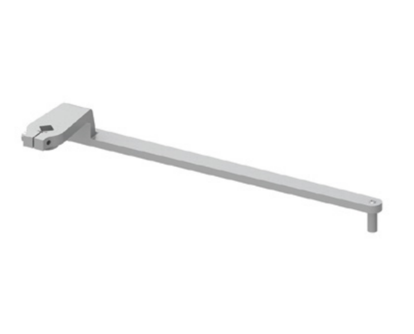
 

Schlage commercial door hardware and L-Series mortise lock parts at SecurityParts.com

Schlage commercial door hardware at SecurityParts.com. OEM L-Series replacement parts including outside lever assemblies, inside levers, cylinders, and case components.


The Three Variables to Specify When Ordering the 09-506 M63

Every 09-506 M63 order requires three specifications. Getting any one of them wrong means the part either will not fit or will not match the existing installation.

1. Finish

The finish code matches the lever to the installed hardware and the door specification. The 09-506 M63 is available in a range of ANSI standard finishes. Common finishes include US26D (satin chrome), US32D (satin stainless), US10B (dark oxidized bronze), and others.

If you are replacing a lever on an existing installation, the finish code is stamped on the hardware or listed on the original lock specification sheet. Ordering a mismatched finish creates a visible discrepancy that is difficult to correct without replacing additional components. For a full finish code reference and matching guidance, see the commercial door hardware finish guide.
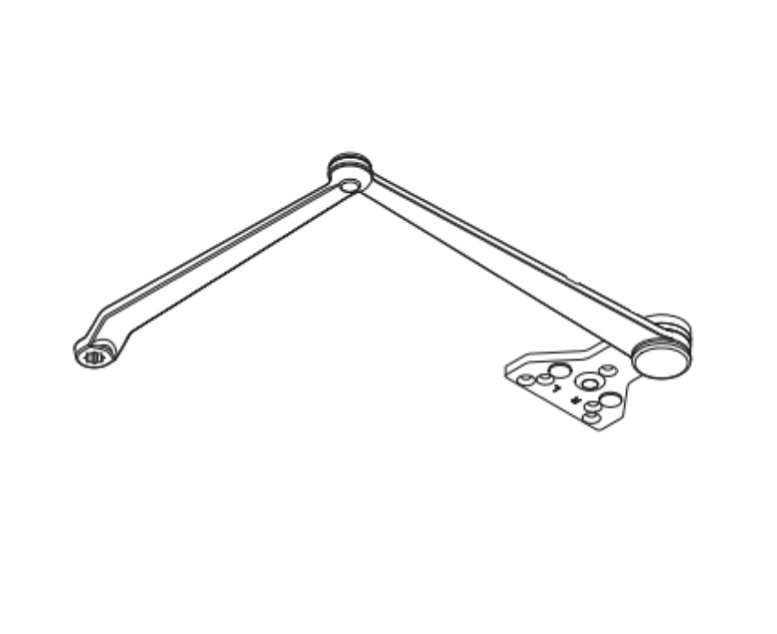
 

2. Rose Style
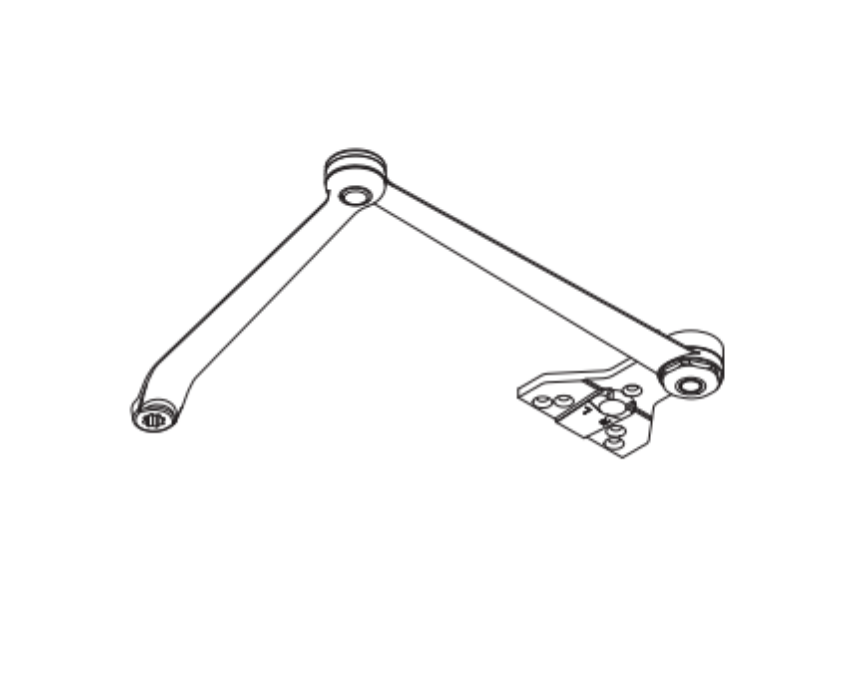
The rose is the plate that surrounds the lever on the door face. Different rose styles match different door preparations and architectural requirements. The rose selection is a required field when ordering the 09-506 M63 through SecurityParts.com.

If you are unsure which rose style is currently installed, the easiest identification method is looking at the shape and size of the existing rose plate on the outside of the door. Confirm the rose style before ordering to avoid a return.

Rose trim vs escutcheon trim: The Schlage 09-506 M63 is a rose trim assembly. L-Series outside lever trim is available in two formats: rose trim (a round or rectangular plate behind the lever) and escutcheon trim (a larger, full-cover plate). If your installation uses escutcheon trim, the part number is different from the 09-506 M63. Confirm which trim format is installed before ordering. If unsure, call 845-935-0301 for identification assistance.


3. Handing

Lever trim is handed, meaning the lever is designed for either a right-hand or left-hand door. Handing is not optional and cannot be adjusted in the field. Ordering the wrong handing results in a lever that mounts incorrectly relative to the door swing.

How to determine handing for the 09-506 M63:

Stand on the outside of the door (the side that has the keyed cylinder). If the hinges are on your left, the door is right-hand (RHR). If the hinges are on your right, the door is left-hand (LHR). For reverse-bevel doors, reverse this determination.

Confirm handing before placing the order. The 09-506 M63 is available in both right-hand and left-hand configurations at SecurityParts.com.


M63 vs M62: Understanding the Lever Style Difference

M63 and M62 are two distinct Schlage lever designs used on the L-Series platform. They are the most frequently confused lever styles when ordering replacement outside trim, because both are common on existing commercial installations and the names are similar.

The M63 and M62 are different in their physical shape and profile. They are not interchangeable. The 09-506 M62 and the 09-506 M63 both use the same base part number (09-506) but are different assemblies that cannot be swapped on an existing installation without also replacing the rose and potentially other trim components.


How to Identify Whether Your Lock Has M63 or M62 Trim

The lever style is typically marked on the original specification sheet provided when the lock was ordered. On installed locks, the most reliable identification method is comparing the physical profile of the existing lever to Schlage's lever style reference materials.

If you cannot determine the lever style from visual inspection alone, the full part number (including the lever style suffix) is typically stamped inside the lock case when the case cover is removed, or is available from the original installation documentation. If none of this is available, SecurityParts.com pre-order support can help confirm the correct lever style. Call 845-935-0301.


Other 09-506 Lever Styles Available at SecurityParts.com

The 09-506 base number covers multiple lever styles for the L-Series. Beyond the M63, the following outside lever assemblies with the 09-506 base number are available at SecurityParts.com:

  • 09-506 ME1, ME1 lever style for L-Series
  • 09-506 M62, M62 lever style (confirm availability with SecurityParts.com)
  • 09-506 M57, M57 lever style (confirm availability with SecurityParts.com)
  • 09-506 M82, M83, M84, M85, M8x lever styles (confirm availability with SecurityParts.com)
  • 09-506 ME2, ME3, ME series lever styles (confirm availability with SecurityParts.com)

Browse the complete outside lever assembly selection through the Schlage L-Series parts catalog at SecurityParts.com.


Schlage M63 vs Von Duprin M63: Two Different Products

This is the most important distinction on this page. The M63 lever design designation is used on both Schlage hardware and Von Duprin hardware, but the two are completely different products for different hardware platforms. They are not interchangeable.

Schlage 09-506 M63: L-Series Outside Lever Assembly

The Schlage 09-506 M63 is the outside trim assembly for Schlage L-Series and LE-Series Grade 1 mortise locks. It installs on the exterior face of the door as the keyed entry side of the L-Series mortise lock. It includes the lever and rose. It does not include the lock case, cylinder, or inside trim.


Von Duprin M63 Lever Kits: Exit Device Trim

The Von Duprin M63 lever kits (part numbers 114842 through 114849) are trim components for Von Duprin exit devices, not for Schlage L-Series mortise locks. These kits include right-hand (RH) and left-hand (LH) configurations for specific Von Duprin models.

Available Von Duprin M63 lever kits at SecurityParts.com:

If you are looking at a door with a Von Duprin exit device on the interior and an outside trim lever, the correct M63 part is from the Von Duprin 114xxx series, not the Schlage 09-506 series. If you are unsure which hardware system is installed, call 845-935-0301 for pre-order identification support.


The Schlage L-Series: Why the Outside Lever Matters

The outside lever on an L-Series mortise lock is the first component to show wear in normal operation, because it takes every entry contact on the exterior side of the door. On high-traffic commercial openings, this can mean hundreds of operations per day. The outside lever assembly is also the component most often damaged by forced entry attempts, environmental exposure on exterior doors, and general use over time.

Replacing just the outside lever assembly, rather than the entire mortise lock chassis, is the standard maintenance approach for worn exterior trim on a functional L-Series lock. The lock case, cylinder, and function hardware are unaffected by an outside lever replacement if the underlying mechanism is still operating correctly.

For a comprehensive breakdown of all L-Series mortise lock parts and their service sequences, see the mortise lock parts guide and the Schlage L-Series parts diagrams guide. For guidance on the L-Series in the context of commercial mortise lock specification and application, see the commercial mortise locks guide.
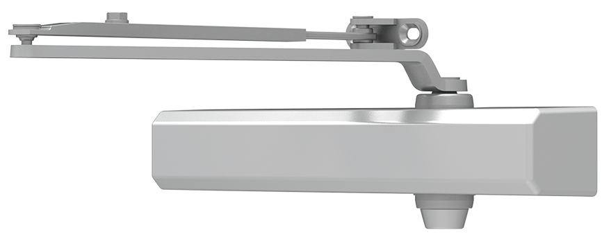
 

Ordering the Schlage 09-506 M63 at SecurityParts.com

SecurityParts.com has supplied OEM Schlage commercial hardware parts since 2001. The 09-506 M63 outside lever assembly is stocked with same-day shipping on available configurations.

To order correctly:

  1. Confirm the lever design is M63 (not M62, M57, or another style)
  2. Determine handing (right-hand or left-hand)
  3. Identify the correct finish code for the installation
  4. Select the correct rose style
  5. Decide whether you also need the 09-402 M63 inside lever

Browse the Schlage 09-506 M63 Outside Lever Assembly at SecurityParts.com. For the full L-Series parts range, see the Schlage L-Series parts catalog. For Schlage key system and cylinder guidance relevant to L-Series installations, see the Schlage key systems guide.
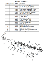
For pre-order configuration assistance, call 845-935-0301 or visit the SecurityParts.com contact page.


About the Author

This guide is published by the commercial door hardware team at SecurityParts.com, a supplier of OEM Schlage, Von Duprin, LCN, Falcon, and Detex parts since 2001. Technical specifications and product availability are verified against live SecurityParts.com product pages and official Schlage L-Series documentation. For 09-506 M63 configuration support and same-day shipping, call 845-935-0301 or visit SecurityParts.com.
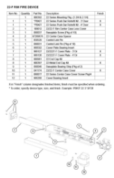
 

Blog|Security Parts

Blog|Security Parts

Blog|Security Parts